Page 49 of 136

Instrument and control functions
4-26
4
To make settin g chan ges
1. Select “Shift IND Setting”.
2. Select “IND Mode”. 3. Select “ON” to have the indicator
light steadily, “OFF” to turn the in-
dicator off, or “Flash” to have the
shift indicator flash when the indi-
cator start threshold has been
reached.
4. Select “IND Start”. 5. Rotate the wheel switch to adjust
the r/min at which the shift timing
indicator light will come on. “IND
Start” operational range is 8000–
14800 r/min.
Set the tachometer peak
rev indicator to “ON” or
“OFF”.
Peak Rev IND Setting
GP GPS
WallpaperUnit
Shift Indicator
Display Setting MENU
Maintenance
Brightness
km/h
10 :
00
GP GPS
Tach IND Setting
Shift IND Brightness
Peak Rev IND Setting Shift Indicator
Shift IND Setting
km/h
10 :
00
1000 r/min
Shift Indicator
km/h
GPS
10 :
00
Shift IND Setting
IND Mode
IND Start
IND Stop ON
10000
r/min
15000
r/min
1000 r/min
Shift Indicator
km/h
GPS
10 :
00
Shift IND Setting
IND Mode
IND Start
IND Stop ON
10000
r/min
15000
r/min
1000 r/min
Shift Indicator
km/h
GPS
10 :
00
Shift IND Setting
IND Mode
IND Start
IND Stop ON
10000
r/min
15000
r/min
1000 r/min
Shift Indicator
km/h
GPS
10 :
00
Shift IND Setting
IND Mode
IND Start
IND Stop ON
10000
r/min
15000
r/min
UB3LE0E0.book Page 26 Tuesday, July 23, 2019 12:05 PM
Page 50 of 136

Instrument and control functions
4-27
4 6. Select “IND Stop”, and then rotate
the wheel switch to adjust the
r/min at which the shift timing indi-
cator will go off. “IND Stop” oper-
ational range is 8500–15000 r/min.
TIPThe blue area on the tachometer indi-
cates the currently set operational
range of the shift indicator light.“Shift IND Bri ghtness”
The shift timing indicator light has six
brightness levels.
Select “Shift IND Brightness”, then use
the wheel switch to adjust the setting.
Short push the wheel switch to confirm
the setting and exit. “Tach IND Settin
g”
This module allows you to turn the ta-
chometer color display on or off. When
turned off, the tachometer will display
all r/min levels below the red zone in
black or white (depending on wallpa-
per settings). When turned on, the mid
and mid-to-high r/min zones can be
set to come on in green and then or-
ange colors. 1. Select “Tach IND Setting”. 2. Select “IND Mode”.
3. Select ON to turn the tachometer
color display mode on (or select
OFF to turn this function off).
GP GPS
Tach IND Setting
Shift IND Brightness
Peak Rev IND Setting Shift Indicator
Shift IND Setting
km/h
10 :
00
Shift Indicator
Shift IND Brightness
km/h
GPS
10 :
00
3
GP GPS
Tach IND Setting
Shift IND Brightness
Peak Rev IND Setting Shift Indicator
Shift IND Setting
km/h
10 :
00
1000 r/min
Shift Indicator
km/h
GPS
10 :
00
Tach IND Setting
IND Mode ON
8000
r/min
11000
r/min
Tach IND 1st
Tach IND 2nd
UB3LE0E0.book Page 27 Tuesday, July 23, 2019 12:05 PM
Page 51 of 136

Instrument and control functions
4-28
4
4. Select “Tach IND 1st” to set the green zone starting r/min.
5. Set the starting r/min by rotating and then short pushing the wheel
switch. All r/min above this value
up to the “Tach IND 2nd” setting
value (or the 14000 r/min red
zone), will be displayed in green.
TIPGreen bar start setting range: 8000–
10000 r/min.6. Select “Tach IND 2nd”. 7. Set the orange color starting r/min
by rotating and then short pushing
the wheel switch. All r/min above
this figure until the 14000 r/min red
zone, will be displayed in orange.
TIPOrange bar start setting range: 8000–
14000 r/min.8. Select the triangle symbol to exit.
“Peak Rev IND Settin g”
This module allows you to turn the rev-
olution peak hold indicator on or off. 1. Select “Peak Rev IND Setting”.
1000 r/min
Shift Indicator
km/h
GPS
10 :
00
Tach IND Setting
IND Mode ON
8000
r/min
11000
r/min
Tach IND 1st
Tach IND 2nd
1000 r/min
Shift Indicator
km/h
GPS
10 :
00
Tach IND Setting
IND Mode ON
8000
r/min
11000
r/min
Tach IND 1st
Tach IND 2nd
1000 r/min
Shift Indicator
km/h
GPS
10 :
00
Tach IND Setting
IND Mode ON
8000
r/min
11000
r/min
Tach IND 1st
Tach IND 2nd
1000 r/min
Shift Indicator
km/h
GPS
10 :
00
Tach IND Setting
IND Mode ON
8000
r/min
11000
r/min
Tach IND 1st
Tach IND 2nd
Shift Indicator
km/h
GPS
10 :
00
1000 r/min
Tach IND Setting
IND Mode ON
8000
r/min
11000
r/min
Tach IND 1st
Tach IND 2nd
UB3LE0E0.book Page 28 Tuesday, July 23, 2019 12:05 PM
Page 52 of 136
 or
OFF (to turn off the indicator).
3. Select the triangle symbol to exit. “Display Se")
Instrument and control functions
4-29
4
2. Select “IND Mode” and then se-lect ON (to turn on the indicator) or
OFF (to turn off the indicator).
3. Select the triangle symbol to exit. “Display Settin
g”
This module allows you to set how the
information display items (like TRIP-1,
ODO, C. TEMP, etc.) are grouped on
the main screen. There are four display
groups. To set the display groups
1. From the MENU screen, select
“Display Setting”.
2. “DISPLAY-1”, “DISPLAY-2”, “DISPLAY-3” and “DISPLAY-4”
are displayed.
3. For example, let’s select “DIS- PLAY-1”.
4. Select “STREET MODE 1-1”.
GP GPS
Tach IND Setting
Shift IND Brightness
Peak Rev IND Setting Shift Indicator
Shift IND Setting
km/h
10 :
00
IND Mode ON
Peak Rev IND Setting Shift Indicatorkm/h
GP GPS
10
:
00
1. Information display item (STREET MODE)
1. Information display item (TRACK MODE)
1 �y2
GPS
N
LCS
QS
LIF 2
ODO
123456
TRIP-1
1234.5
1000 r/min
km
km
km/h
10 :
00
MODE-
APWR
1
TCS
3
SCS
2
EBM
1
T-2
1
N
12
12 34
LAP 01
ODO
km
123456
LATEST
1000 r/min
km/h
123
km/h
123
GEAR
GPS
LCS
QS
LIF
10 :
00
MODE-
APWR
1
TCS
3
SCS
2
EBM
1
T-2
2
1
GP GPS
Unit
Maintenance
Wallpaper
Shift Indicator MENU
Logging
Display Setting
km/h
10 :
00
GP GPS
DISPLAY-3 DISPLAY-2
DISPLAY-4
Display Setting
DISPLAY-1
km/h
10 :
00
UB3LE0E0.book Page 29 Tuesday, July 23, 2019 12:05 PM
Page 53 of 136

Instrument and control functions
4-30
4
5. Select the desired information dis- play item with the wheel switch.
TIPThe information display items which
can be selected are:
A.TEMP: air temperature
C.TEMP: coolant temperature
TRIP-1: tripmeter 1
TRIP-2: tripmeter 2 ODO: odometer
FUEL CON: the amount of fuel con-
sumed
FUEL AVG: average fuel consumption
CRNT FUEL: current fuel consumption
6. Select “STREET MODE 1-2” or
“TRACK MODE” to set the re-
maining DISPLAY-1 group items.
7. Select the triangle symbol to exit. To set the other display groups,
repeat from step 3.
“Brig htness”
This module allows you to adjust the
general brightness level of the display
screen. To set the brightness
1. From the MENU screen, select
“Brightness”.
2. Select the desired brightness level by rotating the wheel switch, and
then short push the wheel switch
to fix the setting.
STREET MODE 1 - 1 A.TEMP
C.TEMP
C.TEMP
Display Setting
DISPLAY-1km/h
GPS
10 :
00
TRACK MODE STREET MODE 1 - 2 STREET MODE 1 - 1 A.TEMP
C.TEMP
C.TEMP
Display Setting
DISPLAY-1km/h
GPS
10 :
00
TRACK MODE STREET MODE 1 - 2
STREET MODE 1 - 1 A.TEMP
C.TEMP
C.TEMP
Display Setting
DISPLAY-1km/h
GPS
10 :
00
TRACK MODE STREET MODE 1 - 2
GP GPS
Wallpaper Unit
Shift Indicator
Display Setting MENU
Maintenance
Brightness
km/h
10 :
00
Brightness
km/h
GPS
10 :
00
2
UB3LE0E0.book Page 30 Tuesday, July 23, 2019 12:05 PM
Page 54 of 136
Instrument and control functions
4-31
4 “Clock”
This module allows you to set the
clock.
To set the clock
1. From the MENU screen, select
“Clock”.
2. When “Clock” is selected, the hours figure will be highlighted. 3. Set the hour by rotating and then
short push the wheel switch.
4. The minutes figure will become highlighted.
5. Set the minutes figure by rotating and then short push the wheel
switch. 6. Short push the wheel switch again
to exit and go back to the MENU
screen.
“All Reset”
This module resets everything, except
the odometer and clock, to its factory
preset or default setting.
Select YES to reset all items. After se-
lecting YES, all items will be reset and
the screen will automatically return to
the MENU screen.
GP GPS
Shift Indicator Wallpaper
Display Setting Brightness MENU
Unit
Clock
km/h
10 :
00
Clock
km/h
10 :
00
11 :
34
Clock
km/h
10 :
00
10 :
34
Clock
km/h
10 :
00
10 34
:
Clock
km/h
10 :
00
10 :
58
UB3LE0E0.book Page 31 Tuesday, July 23, 2019 12:05 PM
Page 55 of 136

Instrument and control functions
4-32
4
EAU12823
Clutch leverTo disengage the drivetrain from the
engine, such as when shifting gears,
pull the clutch lever toward to the han-
dlebar. Release the lever to engage the
clutch and transmit power to the rear
wheel.TIPThe lever should be pulled rapidly and
released slowly for smooth shifting.
(See page 6-3.)
EAU83690
Shift pe dalThe shift pedal is located on the left
side of the motorcycle. To shift the
transmission to a higher gear, move
the shift pedal up. To shift to the trans-
mission to a lower gear, move the the
shift pedal down. (See page 6-3.)
The shift rod is equipped with a shift
sensor, which is part of the quick shift
system. The shift sensor reads up and
down movement, as well as the
strength of the input force when the
shift pedal is moved.
TIPTo prevent unintended shifts, QSS is
programmed to ignore unclear input
signals. Therefore, be sure to shift us-
ing quick and sufficiently forceful in-
puts.
1. Clutch lever
1
1. Shift pedal
2. Shift sensor
1
2
UB3LE0E0.book Page 32 Tuesday, July 23, 2019 12:05 PM
Page 56 of 136

Instrument and control functions
4-33
4
EAU26827
Brake leverThe brake lever is located on the right
side of the handlebar. To apply the
front brake, pull the lever toward the
throttle grip.
The brake lever is equipped with a
brake lever position adjusting dial. To
adjust the distance between the brake
lever and the throttle grip, push the
brake lever away from the throttle grip
and rotate the adjusting dial. Make
sure the setting number on the adjust-
ing dial aligns with the match mark on
the brake lever.
EAU12944
Brake ped alThe brake pedal is located on the right
side of the motorcycle. To apply the
rear brake, press down on the brake
pedal.
EAU88462
Brake control system (BC)The brake control system regulates hy-
draulic brake pressure for the front and
rear wheels independently when the
respective brake lever or brake pedal is
applied and wheel lock is detected.
There are two settings, BC1 and BC2.
BC1 is standard ABS, which adjusts
brake pressure based on vehicle
speed and wheel speed data. BC1 is
designed to engage and maximize
braking when the vehicle is upright.
Regarding ABS, operate the brakes as
you would conventional brakes. When
the brake control system engages, a
pulsating sensation may be felt at the
brake lever or brake pedal as the hy-
draulic unit rapidly applies and reduces
brake pressure. In this situation, con-
tinue to apply the brake lever and
brake pedal to allow the ABS to work—
do not “pump the brakes” as this will
reduce braking effectiveness.
WARNING
EWA16051
Always keep a sufficient d istance
from the vehicle ahea d to match the
ri din g spee d even with ABS.
1. Brake lever
2. Distance
3. Match mark
4. Adjusting dial
1
2
4
3
1. Brake pedal
UB3LE0E0.book Page 33 Tuesday, July 23, 2019 12:05 PM
 1
1 2
2 3
3 4
4 5
5 6
6 7
7 8
8 9
9 10
10 11
11 12
12 13
13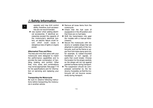 14
14 15
15 16
16 17
17 18
18 19
19 20
20 21
21 22
22 23
23 24
24 25
25 26
26 27
27 28
28 29
29 30
30 31
31 32
32 33
33 34
34 35
35 36
36 37
37 38
38 39
39 40
40 41
41 42
42 43
43 44
44 45
45 46
46 47
47 48
48 49
49 50
50 51
51 52
52 53
53 54
54 55
55 56
56 57
57 58
58 59
59 60
60 61
61 62
62 63
63 64
64 65
65 66
66 67
67 68
68 69
69 70
70 71
71 72
72 73
73 74
74 75
75 76
76 77
77 78
78 79
79 80
80 81
81 82
82 83
83 84
84 85
85 86
86 87
87 88
88 89
89 90
90 91
91 92
92 93
93 94
94 95
95 96
96 97
97 98
98 99
99 100
100 101
101 102
102 103
103 104
104 105
105 106
106 107
107 108
108 109
109 110
110 111
111 112
112 113
113 114
114 115
115 116
116 117
117 118
118 119
119 120
120 121
121 122
122 123
123 124
124 125
125 126
126 127
127 128
128 129
129 130
130 131
131 132
132 133
133 134
134 135
135