2020 YAMAHA YZF-R1 oil change
[x] Cancel search: oil changePage 28 of 136

Instrument and control functions
4-5
4 The LCS icon will flash and turn
white when the system has been
activated.
The traction control system can
only be turned off from the main
screen. Select TCS with the center
button, then push and hold the up
button until TCS OFF is displayed.
To turn the traction control system
back on, use the down button.
When TCS has been turned off,
the SCS, LCS, and LIF systems
are also turned off for all YRC
modes.
See “YRC Setting” on page 4-16
for more information on how to
customize YRC modes and adjust
YRC item setting levels.
EAU66100
Wheel switch “ ”
When the main screen is set to
STREET MODE, use the wheel switch
to scroll and reset the information dis-
play items.
When the main screen is set to TRACK
MODE, use the wheel switch to scroll
and reset the information display items
and to activate the lap timer. When the display has been changed to
the MENU screen, use the wheel
switch to navigate the setting modules
and make setting changes.
Operate the wheel switch as follows.
Rotate up
- rotate the wheel upward to
scroll up/left or increase a setting val-
ue.
Rotate down - rotate the wheel down-
ward to scroll down/right or decrease a
setting value.
Short push - briefly press the switch
inward to make and confirm selec-
tions.
Lon g push - press the switch inward
for one second to reset an information
display item or to access and exit the
MENU screen.
TIP See page 4-9 for more information
on the main screen and its func-
tions.
See page 4-15 for more informa-
tion on the MENU screen and how
to make setting changes.
EAU4939H
Indicator li ghts an d warnin g
li g hts1. Fuel level warning light “ ”
2. Oil pressure and Coolant temperature warn-
ing light “ ”
3. Auxiliary system warning light “ ”
4. Stability control indicator light “ ”
5. Shift indicator light “ ”
6. High beam indicator light “ ”
7. ABS warning light “ ”
8. Malfunction indicator light “ ”
9. Right turn signal indicator light “ ”
10.Left turn signal indicator light “ ”
11.Neutral indicator light “ ”
12.Immobilizer system indicator light “ ”
ABS
1 2
GPSN
LCSQS
LIF 2
ODO123456 TRIP-1
1234.5
1000 r/min
km
km
km/h
10:
00
MODE-APWR 1TCS 3SCS 2EBM 1T-2
5
12
6
7
9
8
1012
11
3
4
UB3LE0E0.book Page 5 Tuesday, July 23, 2019 12:05 PM
Page 37 of 136

Instrument and control functions
4-14
4
Warnin
g icons
When an error is detected, the follow-
ing error-related warning icons will
then be viewable.
SCU trou ble warnin g“” (YZF-R1M)This icon appears if a problem is de-
tected in the front or rear suspension.
Auxiliary system warnin g“”
This icon appears if a problem is de-
tected in a non-engine-related system. Coolant temperature warnin
g“”
This icon appears if the coolant tem-
perature reaches 117 °C (242 °F) or
higher. Stop the vehicle and turn off the
engine. Allow the engine to cool.
NOTICE
ECA10022
Do not continue to operate the en-
g ine if it is overheatin g.Oil pressure warnin g“”
This icon appears when the engine oil
pressure is low. When the vehicle is
first turned on, engine oil pressure has
yet to build, so this icon will come on
and stay on until the engine has been
started.TIPIf a malfunction is detected, the oil
pressure warning icon will flash repeat-
edly.NOTICE
ECA26410
Do not continue to operate the en-
g ine if the oil pressure is low.
Error mo de warnin g “Err”
When an internal error occurs (e.g.,
communication with a system control-
ler has been cut off), the error mode
warning will appear as follows.
“Err” and “ ” indicates an ECU error.
“Err” and “ ” indicates an SCU error.
“Err” only indicates an ABS ECU error.TIPDepending on the nature of the error,
the display may not function properly
and YRC settings may be impossible
to change. Additionally, ABS may not
function properly. Use extra care when
braking and have a Yamaha dealer
check the vehicle immediately.
1. SCU trouble warning “ ”
2. Auxiliary system warning “ ”
3. Coolant temperature warning “ ”
4. Oil pressure warning “ ”
5. Error mode warning “Err”1000 r/min
4
12
5
3
Er r
UB3LE0E0.book Page 14 Tuesday, July 23, 2019 12:05 PM
Page 46 of 136

Instrument and control functions
4-23
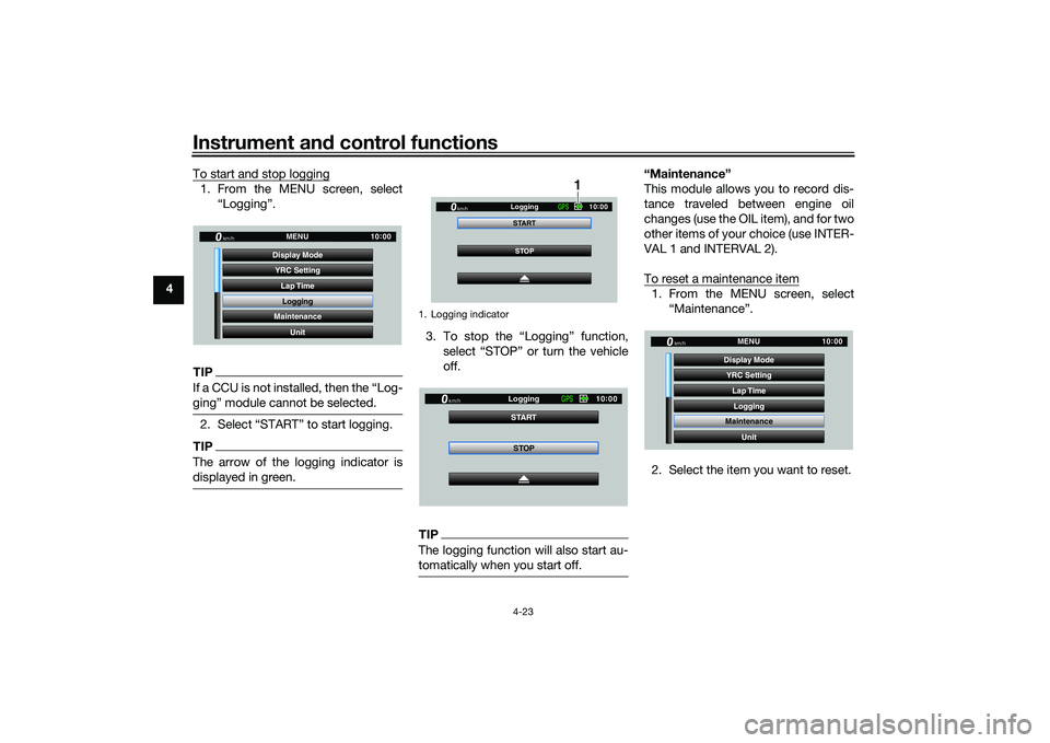
4 To start and stop logging
1. From the MENU screen, select
“Logging”.TIPIf a CCU is not installed, then the “Log-
ging” module cannot be selected.2. Select “START” to start logging.TIPThe arrow of the logging indicator is
displayed in green.
3. To stop the “Logging” function,select “STOP” or turn the vehicle
off.TIPThe logging function will also start au-
tomatically when you start off.
“Maintenance”
This module allows you to record dis-
tance traveled between engine oil
changes (use the OIL item), and for two
other items of your choice (use INTER-
VAL 1 and INTERVAL 2).
To reset a maintenance item1. From the MENU screen, select“Maintenance”.
2. Select the item you want to reset.
YRC Setting Lap TimeLogging
Maintenance
Unit
Display ModeMENU
km/h
GPS
10
:
00
1. Logging indicator
STOP
START
Logging
km/h
10
:
00
GPS
1
STOP
START
Logging
km/h
10
:
00
GPS
YRC Setting
Lap TimeLogging
Maintenance
Unit
Display ModeMENU
km/h
GPS
10
:
00
UB3LE0E0.book Page 23 Tuesday, July 23, 2019 12:05 PM
Page 47 of 136

Instrument and control functions
4-24
4
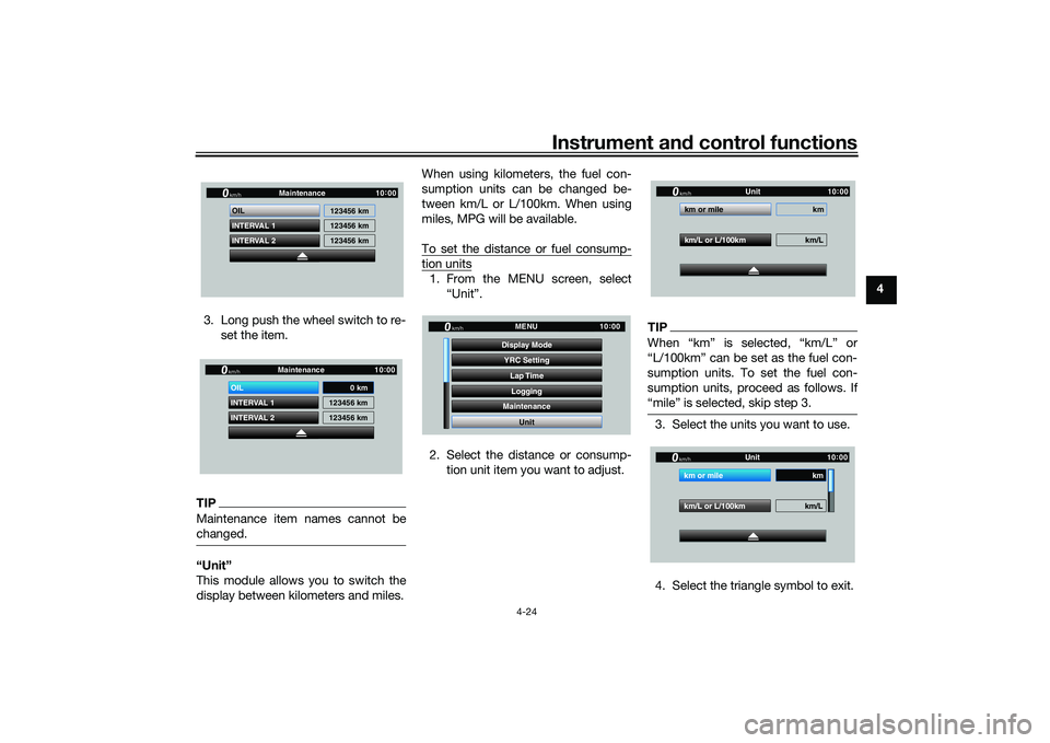
3. Long push the wheel switch to re- set the item.
TIPMaintenance item names cannot be
changed.“Unit”
This module allows you to switch the
display between kilometers and miles. When using kilometers, the fuel con-
sumption units can be changed be-
tween km/L or L/100km. When using
miles, MPG will be available.
To set the distance or fuel consump-
tion units1. From the MENU screen, select
“Unit”.
2. Select the distance or consump- tion unit item you want to adjust.
TIPWhen “km” is selected, “km/L” or
“L/100km” can be set as the fuel con-
sumption units. To set the fuel con-
sumption units, proceed as follows. If
“mile” is selected, skip step 3.3. Select the units you want to use.
4. Select the triangle symbol to exit.
INTERVAL 2 OIL
INTERVAL 1 123456 km
123456 km
123456 km
Maintenancekm/h
GPS
10
:
00
INTERVAL 2 OIL
INTERVAL 1 123456 km
123456 km
Maintenancekm/h
GPS
10
:
00
0 km
YRC Setting
Lap TimeLogging
Maintenance
Unit
Display ModeMENU
km/h
GPS
10
:
00
km/L or L/100km km/L
km or mile km
Unitkm/h
GP GPS
10
:
00
km/L or L/100km km/L
km or mile km
Unitkm/h
GP GPS
10
:
00
UB3LE0E0.book Page 24 Tuesday, July 23, 2019 12:05 PM
Page 88 of 136

Periodic maintenance an d a djustment
7-7
7
20 Si destan d • Check operation.
• Lubricate with lithium-soap-
based grease. √√√√√
21 *Sidestan d switch • Check operation and replace if
necessary. √√√√√√
22 *Front fork • Check operation and for oil leak-
age.
• Replace if necessary. √√√√
23 *Shock a
bsor ber as-
sem bly • Check operation and for oil leak-
age.
• Replace if necessary. √√√√
24 *Rear suspension re-
lay arm an
d con-
nectin g arm
pivotin g points • Check operation.
√√√√
25 En gine oil • Change (warm engine before
draining).
• Check oil level and vehicle for oil leakage. √√√√√√
26 En
gine oil filter car-
tri dge • Replace.
√√√
27 *Coolin g system • Check coolant level and vehicle
for coolant leakage. √√√√√
• Change. Every 3 years
28 *EXUP system • Check operation, cable free play
and pulley position. √√√
29 *Front an
d rear
b rake switches • Check operation.
√√√√√√
NO. ITEM CHECK OR MAINTENANCE JOB
ODOMETER READING
ANNUAL
CHECK
1000 km
(600 mi) 10000 km
(6000 mi) 20000 km
(12000 m
i)30000 km
(18000 mi) 40000 km
(24000 mi)
UB3LE0E0.book Page 7 Tuesday, July 23, 2019 12:05 PM
Page 89 of 136

Periodic maintenance an d a djustment
7-8
7
EAU72811
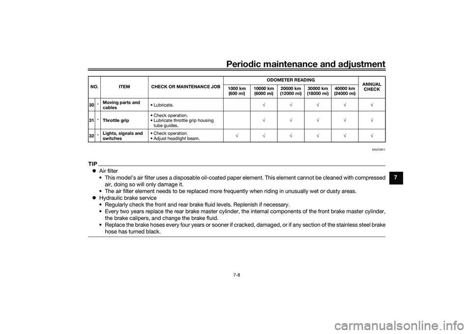
TIP Air filter
• This model’s air filter uses a disposable oil-coated paper element. This element cannot be cleaned with compressed air, doing so will only damage it.
• The air filter element needs to be replaced more frequently when riding in unusually wet or dusty areas.
Hydraulic brake service
• Regularly check the front and rear brake fluid levels. Replenish if necessary.
• Every two years replace the rear brake master cylinder, the internal components of the front brake master cylinder, the brake calipers, and change the brake fluid.
• Replace the brake hoses every four years or sooner if cracked, damaged, or if any section of the stainless steel brake hose has turned black.30 *Movin
g parts an d
ca bles • Lubricate.
√√√√√
31 *Throttle g rip • Check operation.
• Lubricate throttle grip housing
tube guides. √√√√√
32 *Li
ghts, si gnals an d
switches • Check operation.
• Adjust headlight beam.
√√√√√√
NO. ITEM CHECK OR MAINTENANCE JOB
ODOMETER READING
ANNUAL
CHECK
1000 km
(600 mi) 10000 km
(6000 mi) 20000 km
(12000 mi) 30000 km
(18000 mi) 40000 km
(24000 mi)
UB3LE0E0.book Page 8 Tuesday, July 23, 2019 12:05 PM
Page 95 of 136

Periodic maintenance an d a djustment
7-14
7
EAU66536
En gine oil an d oil filter car-
tri dgeThe engine oil level should be checked
before each ride. In addition, the oil
must be changed and the oil filter car-
tridge replaced at the intervals speci-
fied in the periodic maintenance and
lubrication chart.
To check the en gine oil level
1. Place the vehicle on a level sur- face and hold it in an upright posi-
tion. A slight tilt to the side can
result in a false reading.
2. Start the engine, warm it up for several minutes, and then turn it
off.
3. Wait a few minutes for the oil level to settle for an accurate reading,
and then check the oil level
through the check window locat-
ed at the bottom-left side of the
crankcase.TIPThe engine oil should be between the
minimum and maximum level marks.
4. If the engine oil is at or below theminimum level mark, add suffi-
cient oil of the recommended type
to raise it to the correct level.TIPCheck the oil filler cap O-ring for dam-
age, and replace it if necessary.To chan ge the en gine oil
1. Start the engine, warm it up for several minutes, and then turn it
off.
2. Place an oil pan under the engine to collect the used oil. 3. Remove the engine oil filler cap,
the engine oil drain bolt and its
gasket to drain the oil from the
crankcase.1. Engine oil level check window
2. Maximum level mark
3. Minimum level mark
2
3
1
1. Engine oil filler cap
1. Engine oil drain bolt
2. Gasket
12
UB3LE0E0.book Page 14 Tuesday, July 23, 2019 12:05 PM
Page 96 of 136

Periodic maintenance an d a djustment
7-15
7 4. Install the engine oil drain bolt and
its new gasket, and then tighten
the bolt to the specified torque.
5. Refill with the specified amount of the recommended engine oil.
TIPBe sure to wipe off spilled oil on any
parts after the engine and exhaust sys-
tem have cooled down.NOTICE
ECA11621
In or der to prevent clutch slip-
pa ge (since the en gine oil also
lu bricates the clutch), do not
mix any chemical additives. Do not use oils with a
diesel speci-
fication of “CD” or oils of a hi gh-
er quality than specifie d. In
a ddition, do not use oils la beled
“ENERGY CONSERVING II” or
hi gher.
Make sure that no forei gn mate-
rial enters the crankcase.
6. Check the oil filler cap O-ring for damage, and replace it if neces-
sary.
7. Install and tighten the oil filler cap. 8. Start the engine, and then let it idle
for several minutes while checking
it for oil leakage. If oil is leaking,
immediately turn the engine off
and check for the cause.
TIPAfter the engine is started, the oil pres-
sure and coolant temperature warning
light should go off if the oil level is suf-
ficient.NOTICE
ECA22490
If the oil pressure an d coolant tem-
perature warnin g lig ht flickers or re-
mains on even if the oil level is
correct, immed iately turn the en gine
off an d have a Yamaha d ealer check
the vehicle.9. Turn the engine off, wait a few minutes for the oil level to settle for
an accurate reading, and then
check the oil level and correct it if
necessary.
Tightenin g torque:
Engine oil drain bolt: 23 N·m (2.3 kgf·m, 17 lb·ft)
Recommen ded en gine oil:
Full synthetic
10W-40, 15W-50
Oil quantity: Oil change:3.90 L (4.12 US qt, 3.43 Imp.qt)
With oil filter removal: 4.10 L (4.33 US qt, 3.61 Imp.qt)
1. Engine oil filler cap
2. O-ring
12
UB3LE0E0.book Page 15 Tuesday, July 23, 2019 12:05 PM