Page 57 of 136

Instrument and control functions
4-34
4
The ABS performs best with
lon g b rakin g d istances.
On certain surfaces, such as
rou gh or g ravel roa ds, the b rak-
in g d istance may be lon ger with
the ABS than without.
BC2 incorporates standard ABS and in
addition regulates braking power when
cornering to suppress lateral wheel
slip.
WARNING
EWA20891
The brake control system is not a
su bstitute for the use of proper ri d-
in g an d brakin g techniques. The
b rake control system cannot pre-
vent all loss of traction due to over-
b rakin g from excessive spee d, or
lateral wheel slip when brakin g on
slippery surfaces.The ABS hydraulic unit is monitored by
the ABS ECU, which will revert the sys-
tem to conventional braking if a mal-
function occurs.
TIPThe ABS performs a self-diagnosis test
when the vehicle is started and reach-
es a speed of 10 km/h (6 mi/h). During
this test, a clicking noise may be audi-
ble from the hydraulic control unit, and
a vibration may be felt at the brake le-
ver or pedal, but this is normal.NOTICE
ECA20100
Be careful not to d amage the wheel
sensor or wheel sensor rotor; other-
wise, improper performance of the
ABS will result.1. Front wheel sensor rotor
2. Front wheel sensor
1
2
1. Rear wheel sensor rotor
2. Rear wheel sensor
1
2
UB3LE0E0.book Page 34 Tuesday, July 23, 2019 12:05 PM
Page 58 of 136

Instrument and control functions
4-35
4
EAU13076
Fuel tank capTo open the fuel tank cap
Open the fuel tank cap lock cover, in-
sert the key into the lock, and then turn
it 1/4 turn clockwise. The lock will be
released and the fuel tank cap can be
opened.
To close the fuel tank cap
With the key still inserted in the lock,
push down the fuel tank cap. Turn the
key 1/4 turn counterclockwise, remove
it, and then close the lock cover.
TIPThe fuel tank cap cannot be closed un-
less the key is in the lock. In addition,
the key cannot be removed if the cap is
not properly closed and locked.
WARNING
EWA11092
Make sure that the fuel tank cap is
properly close d after fillin g fuel.
Leakin g fuel is a fire hazar d.
EAU13222
FuelMake sure there is sufficient gasoline in
the tank.
WARNING
EWA10882
Gasoline an d g asoline vapors are
extremely flamma ble. To avoi d fires
an d explosions an d to re duce the
risk of injury when refuelin g, follow
these instructions.1. Before refueling, turn off the en- gine and be sure that no one is sit-
ting on the vehicle. Never refuel
while smoking, or while in the vi-
cinity of sparks, open flames, or
other sources of ignition such as
the pilot lights of water heaters
and clothes dryers.
2. Do not overfill the fuel tank. When refueling, be sure to insert the
pump nozzle into the fuel tank filler
hole. Stop filling when the fuel
reaches the bottom of the filler
tube. Because fuel expands when
it heats up, heat from the engine or
the sun can cause fuel to spill out
of the fuel tank.
1. Fuel tank cap lock cover
2. Unlock.
1
2
UB3LE0E0.book Page 35 Tuesday, July 23, 2019 12:05 PM
Page 59 of 136

Instrument and control functions
4-36
4
3. Wipe up any spilled fuel immedi- ately. NOTICE: Immediately
wipe off spille d fuel with a clean,
d ry, soft cloth, since fuel may
d eteriorate painte d surfaces or
plastic parts.
[ECA10072]
4. Be sure to securely close the fuel tank cap.
WARNING
EWA15152
Gasoline is poisonous an d can
cause injury or d eath. Handle gaso-
line with care. Never siphon gasoline
b y mouth. If you shoul d swallow
some gasoline or inhale a lot of gas-
oline vapor, or get some g asoline in
your eyes, see your doctor imme di- ately. If g
asoline spills on your skin,
wash with soap an d water. If gaso-
line spills on your clothin g, chan ge
your clothes.
EAU86072
Your Yamaha engine was designed to
use unleaded gasoline with a research
octane number of 95 or higher. If en-
gine knocking or pinging occurs, use a
gasoline of a different brand or higher
octane rating.
TIP This mark identifies the recom-
mended fuel for this vehicle as
specified by European regulation
(EN228).
Confirm the gasoline pump nozzle
has the same fuel identification
mark.Gasohol
There are two types of gasohol: gaso-
hol containing ethanol and that con-
taining methanol. Gasohol containing
ethanol can be used if the ethanol con-
tent does not exceed 10% (E10). Gas-
ohol containing methanol is not
recommended by Yamaha because it
can cause damage to the fuel system
or vehicle performance problems.
1. Fuel tank filler tube
2. Maximum fuel level
1
2
Recommen ded fuel:
Unleaded gasoline (E10 acceptable)
Octane num ber (RON):
95
Fuel tank capacity: 17 L (4.5 US gal, 3.7 Imp.gal)
Fuel tank reserve:
3.0 L (0.79 US gal, 0.66 Imp.gal)
E5
E10
UB3LE0E0.book Page 36 Tuesday, July 23, 2019 12:05 PM
Page 60 of 136
Instrument and control functions
4-37
4
NOTICE
ECA11401
Use only unlea ded g asoline. The use
of lead ed g asoline will cause severe
d amag e to internal en gine parts,
such as the valves an d piston rin gs,
as well as to the exhaust system.
EAU86160
Fuel tank overflow hoseThe overflow hose drains excess gaso-
line and directs it safely away from the
vehicle.
Before operating the vehicle: Check the fuel tank overflow hose
connection.
Check the fuel tank overflow hose
for cracks or damage, and replace
it if necessary.
Make sure that the fuel tank over-
flow hose is not blocked, and
clean it if necessary.
Make sure that the fuel tank over-
flow hose is positioned as shown.
TIPSee page 7-13 for canister information.
1. Fuel tank overflow hose
2. White mark
1
2
UB3LE0E0.book Page 37 Tuesday, July 23, 2019 12:05 PM
Page 61 of 136
 to reduce harmful exhaust
emissions.
WARNING
EWA10863
The exhaust system is hot a")
Instrument and control functions
4-38
4
EAU13435
Catalytic converterThe exhaust system contains catalytic
converter(s) to reduce harmful exhaust
emissions.
WARNING
EWA10863
The exhaust system is hot after op-
eration. To prevent a fire hazar d or
b urns:
Do not park the vehicle near
possi ble fire hazar ds such as
g rass or other materials that
easily burn.
Park the vehicle in a place
where pe destrians or chil dren
are not likely to touch the hot
exhaust system.
Make sure that the exhaust sys-
tem has coole d down before
d oin g any maintenance work.
Do not allow the en gine to i dle
more than a few minutes. Lon g
i d lin g can cause a buil d-up of
heat.
EAU79902
SeatsPassen ger seat
To remove the passenger seat1. Insert the key into the seat lock, and then turn it clockwise.
2. Lift the front of the passenger seat and pull it forward.
To install the passenger seat1. With the seat lock key still in the open position (turned clockwise),
insert the projection on the rear of
the passenger seat into the seat holder as shown, and then push
the front of the seat down to lock
it in place.
2. Remove the key.
Ri der seat
To remove the rider seat
1. Remove the passenger seat.
2. Pull up the corners on the rear of the rider seat, remove the bolts
with the hexagon wrench (see
page 7-2), and then pull the seat
off.
1. Seat lock
2. Unlock.
1
2
1. Projection
2. Seat holder
2
1
UB3LE0E0.book Page 38 Tuesday, July 23, 2019 12:05 PM
Page 62 of 136

Instrument and control functions
4-39
4
To install the rider seat
1. Insert the projection into the seatholder as shown, then place the
seat in the original position. 2. Install the bolts with the hexagon
wrench.
3. Insert the hexagon wrench back into its holder.
4. Install the passenger seat.
TIPMake sure that the seats are properly
secured before riding.
EAU67156
CCU (for equippe d mo dels)The CCU (communication control unit)
connects to the vehicle’s CAN (control-
ler area network) and has a GPS re-
ceiver to enable the recording of
vehicle and riding data (see “Logging”
on page 4-22). Logging data and YRC
setting data can be accessed when a
smartphone or tablet is connected to
the CCU wireless network.TIPFrom the Google© or Apple© applica-
tion store, download the “Y-TRAC” ap-
plication to make use of the logging
data and the “YRC Setting” application
to remotely adjust the YRC settings.To connect to the CCU wireless net-work1. Remove the screws, move the
GPS receiver, and then remove
the seat cover as shown.
1. Bolt
1. Hexagon wrench
1
1
1. Projection
2. Seat holder
21
UB3LE0E0.book Page 39 Tuesday, July 23, 2019 12:05 PM
Page 63 of 136
Instrument and control functions
4-40
4
2. Note down the CCU serial num- ber.
3. Turn the key to “ON” and ap- proach the vehicle with a wireless
capable smartphone or tablet. 4. Connect to the wireless network
“YAMAHA MOTOR CCU” by in-
putting the CCU serial number as
the password.
5. Install the seat cover and GPS re- ceiver to the original position, and
then install the screws.
TIPSince all CCU-equipped models put
out a similarly named wireless network,
have only one vehicle turned on at a
time to avoid confusion.
EAU88830
Seat cover (for equippe d mo d-
els)When the seat cover is attached, the
total number of occupants is reduced
to one person. Depending on your ar-
ea’s regulations, it may be necessary
to change the vehicle’s registration to
reflect this. Contact your local authori-
ties.
1. Screw
2. Seat cover
3. GPS receiver
1. CCU serial number
1
1
2
3
1
UB3LE0E0.book Page 40 Tuesday, July 23, 2019 12:05 PM
Page 64 of 136

When storing the owner’s manual or
vehicle registration and insur")
Instrument and control functions
4-41
4
EAU66920
Document storag eA document storage space is located
under panel B. (See page 7-9.)
When storing the owner’s manual or
vehicle registration and insurance doc-
uments in the document storage
space, be sure to wrap them in a plas-
tic bag so that they will not get wet.
When washing the vehicle, avoid let-
ting water enter the document storage
space.
NOTICE
ECA22540
Do not place heat-sensitive items in
the document stora ge space. This
space can g et hot when the en gine
is runnin g or when the vehicle is in
d irect sunli ght.
EAU39672
Rear view mirrorsThe rear view mirrors of this vehicle
can be folded forward or backward for
parking in narrow spaces. Fold the mir-
rors back to their original position be-
fore riding.
WARNING
EWA14372
Be sure to fol d the rear view mirrors
b ack to their ori ginal position before
ri din g.
1. Panel B
2. Document storage space
1
2
1. Riding position
2. Parking position11
22
UB3LE0E0.book Page 41 Tuesday, July 23, 2019 12:05 PM
 1
1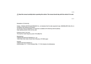 2
2 3
3 4
4 5
5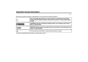 6
6 7
7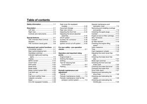 8
8 9
9 10
10 11
11 12
12 13
13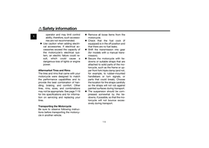 14
14 15
15 16
16 17
17 18
18 19
19 20
20 21
21 22
22 23
23 24
24 25
25 26
26 27
27 28
28 29
29 30
30 31
31 32
32 33
33 34
34 35
35 36
36 37
37 38
38 39
39 40
40 41
41 42
42 43
43 44
44 45
45 46
46 47
47 48
48 49
49 50
50 51
51 52
52 53
53 54
54 55
55 56
56 57
57 58
58 59
59 60
60 61
61 62
62 63
63 64
64 65
65 66
66 67
67 68
68 69
69 70
70 71
71 72
72 73
73 74
74 75
75 76
76 77
77 78
78 79
79 80
80 81
81 82
82 83
83 84
84 85
85 86
86 87
87 88
88 89
89 90
90 91
91 92
92 93
93 94
94 95
95 96
96 97
97 98
98 99
99 100
100 101
101 102
102 103
103 104
104 105
105 106
106 107
107 108
108 109
109 110
110 111
111 112
112 113
113 114
114 115
115 116
116 117
117 118
118 119
119 120
120 121
121 122
122 123
123 124
124 125
125 126
126 127
127 128
128 129
129 130
130 131
131 132
132 133
133 134
134 135
135
