Page 33 of 136

Instrument and control functions
4-10
4
TRACK MODE
WARNING
EWA18210
Stop the vehicle
before makin g any
settin g chan ges. Chan gin g settin gs
while ri din g can distract the opera-
tor an d increase the risk of an acci-
d ent.
Speed ometer
The speedometer shows the vehicle’s
traveling speed.TIPThe display can be switched between
kilometers and miles. See “Unit” on
page 4-24.Tachometer
The tachometer shows the engine
speed, as measured by the rotational
velocity of the crankshaft, in revolu-
tions per minute (r/min).TIP In TRACK MODE, the tachometer
starts at 8000 r/min.
In STREET MODE, the tachometer
can be color-adjusted and has a
revolution peak hold indicator
which can be turned on or off.NOTICE
ECA10032
Do not operate the en gine in the ta-
chometer red zone.
Re d zone: 14000 r/min an d a bove
Information display
This section of the main screen is used
to show additional riding related infor-
mation such as air and coolant temper-
ature readings, tripmeters, and fuel
consumption statistics. The informa-
tion display items can be set into four
groups via the MENU screen.
The information display items are:
A.TEMP: air temperature
C.TEMP: coolant temperature
TRIP-1: tripmeter 1
TRIP-2: tripmeter 2
F-TRIP: fuel tripmeter
ODO: odometer
FUEL CON: the amount of fuel con-
sumed
FUEL AVG: average fuel consumption
CRNT FUEL: current fuel consumptionTIP ODO will lock at 999999 and can-
not be reset.
TRIP-1 and TRIP-2 will reset to 0
and begin counting again after
9999.9 has been reached.
1. YRC items LCS/QS/LIF/BC
2. Lap timer
3. GPS indicator (CCU-equipped models)
4. Logging indicator (CCU-equipped models)
5. Clock
6. Transmission gear display
7. Information display
8. ERS indicator (YZF-R1M)
9. YRC items MODE/PWR/TCS/SCS/EBM
10.Speedometer
11.Tachometer
N
12
12 34
LAP 01
ODO
km
123456
LATEST
1000 r/min
km/h
123
km/h
123
GEAR
GPS
LCS
QS
LIF
10:
00
MODE-
APWR
1
TCS
3
SCS
2
EBM
1
T-2
29
1
8
1110
2
6
7
3
5
4
UB3LE0E0.book Page 10 Tuesday, July 23, 2019 12:05 PM
Page 34 of 136

Instrument and control functions
4-11
4
When the fuel tank reserve level
has been reached, F-TRIP ap-
pears automatically and begins
recording distance traveled from
that point.
After refueling and traveling some
distance, F-TRIP will automatically
disappear.
See “Unit” on page 4-24 to
change the fuel consumption
units.
The air temperature displayed
may vary from the actual ambient
temperature.
In TRACK MODE, information dis-
play items FASTEST (fastest lap
time) and AVERAGE (average lap
time) are also available.
TRIP-1, TRIP-2, F-TRIP, FUEL CON,
and FUEL AVE items can be individual-
ly reset.
To reset information display items1. Use the wheel switch to scroll
through the display items until the
item you want to reset appears. 2. Short push the wheel switch and
the item will flash for five seconds.
(For STREET MODE, if both items
are resettable items, the top item
will flash first. Scroll down to se-
lect the bottom item.)
3. While the item is flashing, press and hold the wheel switch for one
second.
Transmission gear display
This shows which gear the transmis-
sion is in. This model has 6 gears and a
neutral position. The neutral position is
indicated by the neutral indicator
light “ ” and by the transmission gear
display “ ”.
Front brake pressure in dicator
This shows how much braking power
is being applied to the front brakes.
Acceleration in dicator
This shows the vehicle’s forward ac-
celeration and deceleration forces. Revolution peak hol
d in dicator
This small bar momentarily appears
within the tachometer to mark the most
recent peak engine speed.
YRC items
MODE/PWR/TCS/SCS/EBM
The current MODE (YRC mode) and its
related PWR, TCS, SCS, and EBM set-
tings are shown here.
The individual settings for YRC items
PWR, TCS, SCS, LCS, QSS, LIF, EBM,
and BC can be organized into four
groups and set independently for each
group. These groups of settings are the
YRC modes MODE-A, MODE-B,
MODE-C, and MODE-D. Use the mode
switch to change YRC modes or make
YRC item setting changes from the
main screen.
TIPThe YRC modes come preset from the
factory for different riding conditions.
When using the factory presets, the
suggested YRC modes are as follows.
MODE-A: suitable for track riding
MODE-B: softer track-riding setting
MODE-C: suitable for road use
UB3LE0E0.book Page 11 Tuesday, July 23, 2019 12:05 PM
Page 35 of 136

Instrument and control functions
4-12
4
MODE-D: street use or rainy weather
To change YRC modes or make set-ting changes1. Push the mode switch center but-
ton to scroll left to right and high-
light the item you want to adjust.
2. Use the mode switch up button or down button to change the select-
ed item value (vertical scrolling is
not possible).
TIPWhen the malfunction indicator
light is on, YRC settings cannot be
adjusted.
When a YRC function is actively
engaged that item cannot be ad-
justed. For example, when decel-
erating EBM cannot be adjusted.
When a YRC item is highlighted
but cannot be adjusted, the YRC
item box will return to black.To turn off the traction control system,
select TCS with the center button, then
push and hold the up button until TCS
OFF is displayed. To turn TCS back on,
select TCS OFF and then press the
down button (TCS will return to its pre-
vious setting).
TIPTurning off the traction control system
will turn off the SCS, LCS, and LIF sys-
tems for all YRC modes.YRC items LCS/QS/LIF/BC
The on/off status of YRC items LCS,
QSS, LIF, and BC is shown here. When
any of these systems are registered
(not set to OFF) for the currently select-
ed YRC mode, its respective icon will
appear.
When LCS is registered for the current-
ly selected YRC mode, its icon will be
grey. To activate the launch control
system, press and hold the center but-
ton until the LCS icon stops flashing
and turns white.TIPLCS, QSS, LIF, and BC system setting
levels can only be adjusted from the
MENU screen.ERS in dicator “ ” (YZF-R1M)
This icon shows the current ERS
mode. (See “YRC Setting” on page
4-16 and “ERS” on page 4-19 to
1. Mode switch “MODE”
2. Up button
3. Center button
4. Down button
1 2
3
4
N
12
12 34
LAP 01
ODO
km
123456
LATEST
1000 r/min
km/h
123
km/h
123
GEAR
GPS
LCS
QS
LIF
10 :
00
MODE-
APWR
1
TCS
3
SCS
2
EBM
1
T-2
2
MODE -
A
MODE-
A
UB3LE0E0.book Page 12 Tuesday, July 23, 2019 12:05 PM
Page 36 of 136
 If the ERS
mode disappears from the ERS indica-
tor (the icon turns blank), stop the vehi-
cle and")
Instrument and control functions
4-13
4 change the registered ERS mode or
adjust ERS setting levels.) If the ERS
mode disappears from the ERS indica-
tor (the icon turns blank), stop the vehi-
cle and wait a few seconds until the
mode reappears.
TIP
The suspension will remain fixed
at its most recent settings until
self-reset has completed.
If the ERS indicator does not re-
turn to normal, have a Yamaha
dealer inspect the vehicle.GPS in dicator “ ”
(CCU-equippe d mo dels)
This icon comes on when a GPS unit is
synched with your vehicle.
Lo gg ing in dicator “ ”
(CCU-equipped models)
This icon comes on when vehicle data
is being recorded via the logging func-
tion.
Clock
The clock uses a 12-hour time system. Lap timer
This stopwatch function measures and
records up to forty laps. On the main
screen, the lap timer shows the current
lap time and lap number (indicated by
the LAP mark). Use the Pass/LAP
switch to mark lap times. When a lap is
completed, the lap timer will show the
latest lap time (marked by the LATEST
indicator) for five seconds.
To use the lap timer
1. Short push the wheel switch. The
information display item will flash
for five seconds. 2. While the information display item
is flashing, rotate the wheel switch
upward. The lap timer will flash for
five seconds.
3. While the lap timer is flashing, long push the wheel switch to activate
the lap timer or stop the lap timer.
4. When the lap timer has been acti- vated, press the Pass/LAP switch
to start the lap timer.
TIPThe engine must be running to use
the lap timer.
Set the information display to
FASTEST or AVERAGE for addi-
tional lap time information.
Accessing the MENU screen will
automatically stop the lap timer.
Whenever the lap timer is
stopped, the current lap will not be
recorded.
The lap time record can be viewed
and reset from the MENU screen.
GPS
1. Lap time
2. Latest lap time indicator “LATEST”
3. Information display item
4. Lap number
N
12
12 34
LAP 01
ODO
km
123456
LATEST
1000 r/min
km/h
123
km/h
123
GEAR
GPS
LCS
QS
LIF
10:
00
MODE-
APWR
1
TCS
3
SCS
2
EBM
1
T-2
3
4
1
22
UB3LE0E0.book Page 13 Tuesday, July 23, 2019 12:05 PM
Page 37 of 136
This icon appe")
Instrument and control functions
4-14
4
Warnin
g icons
When an error is detected, the follow-
ing error-related warning icons will
then be viewable.
SCU trou ble warnin g“” (YZF-R1M)This icon appears if a problem is de-
tected in the front or rear suspension.
Auxiliary system warnin g“”
This icon appears if a problem is de-
tected in a non-engine-related system. Coolant temperature warnin
g“”
This icon appears if the coolant tem-
perature reaches 117 °C (242 °F) or
higher. Stop the vehicle and turn off the
engine. Allow the engine to cool.
NOTICE
ECA10022
Do not continue to operate the en-
g ine if it is overheatin g.Oil pressure warnin g“”
This icon appears when the engine oil
pressure is low. When the vehicle is
first turned on, engine oil pressure has
yet to build, so this icon will come on
and stay on until the engine has been
started.TIPIf a malfunction is detected, the oil
pressure warning icon will flash repeat-
edly.NOTICE
ECA26410
Do not continue to operate the en-
g ine if the oil pressure is low.
Error mo de warnin g “Err”
When an internal error occurs (e.g.,
communication with a system control-
ler has been cut off), the error mode
warning will appear as follows.
“Err” and “ ” indicates an ECU error.
“Err” and “ ” indicates an SCU error.
“Err” only indicates an ABS ECU error.TIPDepending on the nature of the error,
the display may not function properly
and YRC settings may be impossible
to change. Additionally, ABS may not
function properly. Use extra care when
braking and have a Yamaha dealer
check the vehicle immediately.
1. SCU trouble warning “ ”
2. Auxiliary system warning “ ”
3. Coolant temperature warning “ ”
4. Oil pressure warning “ ”
5. Error mode warning “Err”1000 r/min
4
12
5
3
Er r
UB3LE0E0.book Page 14 Tuesday, July 23, 2019 12:05 PM
Page 38 of 136

Instrument and control functions
4-15
4
EAU79297
MENU screenThe MENU screen contains the follow-
ing setting modules. Select a module
to make related setting changes. Al-
though some settings can be changed
or reset via the main screen, the MENU
screen offers access to all display and
control settings. MENU access an
d operation
The following wheel switch operations
are common operations for accessing,
selecting, and moving within the
MENU screen and its modules.
Lon g push - press and hold the wheel
switch for one second to access the
MENU screen or exit MENU entirely.
Select - rotate the wheel switch up or
down to highlight the desired module
or setting item and then short push the
wheel switch (briefly press the wheel
switch inward) to confirm the selection. Trian
gle mark - certain setting
screens have an upward pointing trian-
gle mark item. Select the triangle mark
to save setting changes made and exit
that screen.
TIP Should vehicle motion be detect-
ed, the screen will automatically
exit MENU and change to the
main screen.
To ensure that the desired setting
changes are saved, be sure to exit
via the triangle mark. Simply per-
forming a long push and exiting
the MENU screen entirely may not
save setting changes.“Display Mo de”
There are two main screen display
modes, STREET MODE and TRACK
MODE.
To set the main screen display mode1. From the MENU screen, select “Display Mode”.
Mo dule Description
Switch the main screen
display between street and
track modes.
Adjust YRC settings (all
models) and ERS settings
(YZF-R1M).
View and reset lap times.
Turn vehicle information
logging function on/off
(CCU-equipped models).
YRC Setting
Lap TimeLogging
Maintenance
Unit
Display ModeMENU
km/h
GPS
10
:
00
Display ModeYRC SettingLogging
View and reset three main-
tenance item intervals.
Set fuel consumption and
distance units.
Set background colors.
Turn the shift indicator
on/off and adjust tachom-
eter settings.
Set the multi-function dis-
play window items.
Adjust screen brightness.
Adjust the clock.
Return all settings to fac-
tory default settings.
Maintenance
Unit
WallpaperShift IndicatorDisplay SettingBrightnessClockAll Reset
UB3LE0E0.book Page 15 Tuesday, July 23, 2019 12:05 PM
Page 39 of 136
.
3. Long push the wheel switch to exit the MENU screen or use the wheel")
Instrument and control functions
4-16
4
2. Select “STREET MODE” or “TRACK MODE” (or select the tri-
angle mark to exit).
3. Long push the wheel switch to exit the MENU screen or use the wheel
switch to select another module. “YRC Settin
g”
This module allows you to customize
the four YRC modes MODE-A, MODE-
B, MODE-C, and MODE-D by adjust-
ing the setting levels (or on/off status
as applicable) of YRC items PWR,
TCS, SCS, LCS, QSS, LIF, EBM, and
BC. For YZF-R1M, you can select the
ERS mode to be associated with each
YRC mode, and also adjust the setting
levels of the ERS modes.
TIP TCS has 9 setting levels and ERS
has 6 modes.
Whenever there are more selec-
tions (setting levels or modes)
available than can be shown on
the screen at one time, a scroll bar
will appear to notify you that addi-
tional selections are available by
scrolling.PWR
Select PWR-1 for the most aggressive
throttle response, PWR-2 and PWR-3
for smoother throttle grip/engine re- sponse, and use PWR-4 for rainy days
or whenever less engine power is de-
sirable.
TCS
This model uses a variable traction
control system. For each setting level,
the further the vehicle is leaned over,
the greater the amount of traction con-
trol (system intervention) is applied.
There are 9 setting levels available.
Setting level 1 applies the least amount
YRC Setting
Lap TimeLogging
Maintenance
Unit
Display ModeMENU
km/h
GPS
10
:
00
km/h
10 :
00
TRACK MODE
STREET MODE
Display Mode
1. PWR 1
2. PWR 2
3. PWR 3
4. PWR 4
5. Throttle valve opening
6. Throttle grip operation
5
64
3 2
1
UB3LE0E0.book Page 16 Tuesday, July 23, 2019 12:05 PM
Page 40 of 136

Instrument and control functions
4-17
4 of overall system intervention, while
setting level 9 applies the greatest
amount of overall traction control.
TIP
TCS can only be turned on or off
via the main screen using the
mode switch.
When TCS has been turned off,
TCS, SCS, LCS, and LIF will be set
to OFF and cannot be adjusted.
When TCS is turned on again,
these related-traction control
functions will return to their previ-
ous setting levels.
SCS
SCS can be set to OFF, 1, 2, and 3.
OFF turns the slide control system off,
setting level 1 provides the least
amount of system intervention, and
setting level 3 provides the greatest
amount of system intervention.
LCS
LCS can be set to 1, 2, or OFF. Setting
level 1 keeps engine speed from rising
above 9000 r/min even when the throt-
tle grip is fully turned. Setting level 2
keeps engine speed from rising above
8000 r/min. OFF disables the LCS
function from the selected YRC mode (the LCS icon will not appear and the
launch control function cannot be acti-
vated).
When LCS has been set to level 1 or 2
for the selected YRC mode, the LCS
indicator on the main screen will ap-
pear in a grey color to indicate that
LCS is available. When the launch con-
trol system has been activated (made
ready for use via the mode switch), the
LCS indicator will turn white.
TIPLCS works in conjunction with the LIF
system. LCS cannot be used if LIF is
turned off.QSS
The quick shift system is divided into
QS (upshift) and QS (downshift)
sections. QS and QS are not
linked and can be independently
turned on or off.
QS can be set to 1, 2, or OFF. Set-
ting level 1 is designed for maximum
acceleration, while setting level 2 is de-
signed to give smooth shifts at halfway
or less throttle openings. OFF turns the
1. System intervention
2. Lean angle
1
TCS
2
1 5
4 3
2 6 9
8 7
1. System intervention
2. Sideward slide
1 3
2
1
SCS
2
UB3LE0E0.book Page 17 Tuesday, July 23, 2019 12:05 PM
 1
1 2
2 3
3 4
4 5
5 6
6 7
7 8
8 9
9 10
10 11
11 12
12 13
13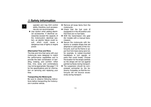 14
14 15
15 16
16 17
17 18
18 19
19 20
20 21
21 22
22 23
23 24
24 25
25 26
26 27
27 28
28 29
29 30
30 31
31 32
32 33
33 34
34 35
35 36
36 37
37 38
38 39
39 40
40 41
41 42
42 43
43 44
44 45
45 46
46 47
47 48
48 49
49 50
50 51
51 52
52 53
53 54
54 55
55 56
56 57
57 58
58 59
59 60
60 61
61 62
62 63
63 64
64 65
65 66
66 67
67 68
68 69
69 70
70 71
71 72
72 73
73 74
74 75
75 76
76 77
77 78
78 79
79 80
80 81
81 82
82 83
83 84
84 85
85 86
86 87
87 88
88 89
89 90
90 91
91 92
92 93
93 94
94 95
95 96
96 97
97 98
98 99
99 100
100 101
101 102
102 103
103 104
104 105
105 106
106 107
107 108
108 109
109 110
110 111
111 112
112 113
113 114
114 115
115 116
116 117
117 118
118 119
119 120
120 121
121 122
122 123
123 124
124 125
125 126
126 127
127 128
128 129
129 130
130 131
131 132
132 133
133 134
134 135
135