Page 193 of 396

IN CASE OF EMERGENCY 191
REPLACING EXTERIOR BULBS
NOTE:
Lens fogging can occur under certain atmo -
spheric conditions. This will usually clear as
a t
mospheric conditions change to allow the
condensation to change back into a vapor.
Turning the lamps on will usually accelerate the
clearing process.
Front Low/High Beam Headlamp, Turn
Signal/Park Lamp, And Side Marker Lamp
1. Open the hood.
NOTE:
It may be necessary to remove the air cleaner
f i
lter housing and position the Totally Integrated
Power Module (TIPM) aside to replace certain
lamps in the left headlamp housing. 2. R
otate the applicable bulb and connector
a
ssembly a quarter turn counterclockwise
and remove the assembly from the
headlamp housing.
Headlamp Housing
3. Disconnect the bulb from the harness
c onnector and then connect the
replacement bulb.
4. I nstall the bulb and connector assembly
i
nto the headlamp housing and rotate it a
quarter turn clockwise to lock it in place.
Exterior Bulbs — Rear (Bulb Version)
Bulb Name Bulb Number
Rear Tail/Stop/Turn Signal Lamp P27/7W or 3157
Rear Tail (Liftgate) Lamp P27/7W or 3157
Backup Lamp P27/7W or 3157
1 — Front Turn Signal/Park Lamp Bulb
2 — Side Marker Lamp Bulb
3 — Low Beam Headlamp Bulb
4 — High Beam Headlamp Bulb
CAUTION!
Do not touch the new bulb with your fingers.
Oil contamination will severely shorten bulb
life. If the bulb comes in contact with any oily
surface, clean the bulb with rubbing alcohol.6
Page 194 of 396

192 IN CASE OF EMERGENCY
Front Fog Lamp
NOTE:
Turn the steering wheel to the right if replacing
t h
e left front fog lamp or to the left if replacing
the right front fog lamp to allow for easier
access to the front of the wheel well.
1. Remove the fasteners retaining the front l
ower wheel well access panel and remove
the access panel.
2. R emove the electrical connector from the
f
og lamp housing.
Front Fog Lamp Electrical Connector
3. S
queeze the two tabs on the side of the bulb
s
ocket and pull straight out from the fog lamp.
4. I nstall the replacement bulb and connector
a
ssembly straight into the fog lamp until it
locks into place.
5. R einstall the front lower wheel well access
p
anel and fasteners.
Rear Turn Signal And Backup Lamp
The tail lamps are a two-piece design. The tail/
stop/rear turn signal lamps are located in the
rear corner body panels. The tail and backup
lamps are located in the liftgate.
License Plate Lamp
1. Push the small locking tab sticking out of the end of the lens toward the side of the
vehicle and hold it in that position.
License Lamp
2. I nsert a small flat-blade tool between the
e
nd of the lens with the locking tab and the
surrounding housing and then pivot the tool
to separate the lens from the housing.
CAUTION!
Never introduce leaded fuel to the tank, even
in small amounts in an emergency, as this
would damage the catalytic converter beyond
repair.
Page 195 of 396

IN CASE OF EMERGENCY 193
3. Hold the lens with one hand and rotate the
bulb's electrical connector a quarter turn
counterclockwise, with the other hand
separate the bulb and connector assembly
from the lens.
4. R emove the bulb from the connector socket
a
nd install the replacement bulb.
5. I nstall the bulb and connector assembly
i
nto the lens and rotate the connector a
quarter turn clockwise to lock it in place.
6. I nsert the end of the lens without the
l
ocking tab into the housing on the liftgate
and then push the opposite end of the lens
into the housing, making sure it locks into
the housing.
FUSESINTERIOR FUSES
The interior fuse panel is located on the
passenger side under the instrument panel.
Interior Fuse Panel Location
To remove fuse cover press on tabs shown.
Interior Fuse Panel Tabs
WARNING!
When replacing a blown fuse, always use
an appropriate replacement fuse with the
same amp rating as the original fuse. Never
replace a fuse with another fuse of higher
amp rating. Never replace a blown fuse with
metal wires or any other material. Do not
place a fuse inside a circuit breaker cavity
or vice versa. Failure to use proper fuses
may result in serious personal injury, fire
and/or property damage.
Before replacing a fuse, make sure that the
ignition is off and that all the other services
are switched off and/or disengaged.
If the replaced fuse blows again, contact an
authorized dealer.
If a general protection fuse for safety
systems (air bag system, braking system),
power unit systems (engine system, trans -
mission system) or steering system blows,
c o
ntact an authorized dealer.
6
Page 196 of 396
194 IN CASE OF EMERGENCY
Cavity Cartridge Fuse Mini-Fuse Description
F10030 Amp Pink –110 Volt AC Inverter – If Equipped
F101 –10 Amp RedInterior Lights
F102 –20 Amp Yellow Cigar Lighter in Instrument Panel/Left Rear Power Outlet
F103 –20 Amp Yellow Power Outlet in Console Bin/Power Outlet in Rear of Console
F105 –20 Amp Yellow Heated Seats – If Equipped
F106 –20 Amp Yellow Rear Power Outlet
F107 –10 Amp RedRear Camera – If Equipped
F108 –15 Amp BlueInstrument Panel
F109 –10 Amp RedClimate Control/HVAC
F110 –10 Amp RedOccupant Restraint Controller
F112 –10 Amp RedSpare
F114 –20 Amp Yellow Rear HVAC Blower/Motor
F115 –20 Amp Yellow Rear Wiper Motor
F116 30 Amp Pink –Rear Defroster (EBL)
F117 –10 Amp RedHeated Mirrors
F118 –10 Amp RedOccupant Restraint Controller
Page 197 of 396
IN CASE OF EMERGENCY 195
F119 –10 Amp RedSteering Column Control Module
F120 –10 Amp RedAll Wheel Drive – If Equipped
F121 –15 Amp BlueWireless Ignition Node
F122 –25 Amp ClearDriver Door Module
F123 –25 Amp ClearPassenger Door Module
F124 –10 Amp RedMirrors
F125 –10 Amp RedSteering Column Control Module
F126 –25 Amp ClearAudio Amplifier
F127 –20 Amp Yellow Trailer Tow – If Equipped
F128 –15 Amp BlueRadio
F129 –15 Amp BlueVideo/DVD – If Equipped
F130 –15 Amp BlueClimate Control/Instrument Panel
F131 –10 Amp RedPassenger Assistance/Hands Free System – If Equipped
F132 –10 Amp RedTire Pressure Module
F133 –10 Amp RedCyber Security Gateway
Cavity Cartridge Fuse Mini-FuseDescription
6
Page 198 of 396
196 IN CASE OF EMERGENCY
UNDERHOOD FUSES (POWER
D
ISTRIBUTION CENTER)
The power distribution center is located in the
engine compartment.
Power Distribution Center
CavityCartridge Fuse Mini-Fuse Description
F10160 Amp Yellow –Interior Power Distribution Center Rail
F102 60 Amp Yellow –Interior Power Distribution Center Rail
F103 60 Amp Yellow –Interior Power Distribution Center Rail
F105 60 Amp Yellow –Interior Power Distribution Center Rail Ignition Run Relay
F106 60 Amp Yellow –Interior Power Distribution Center Rail Run/Accessory Relays
F139 40 Amp Green –Climate Control System Blower
F140 30 Amp Pink –Power Locks
F141 40 Amp Green –Anti-Lock Brake System
Page 199 of 396
IN CASE OF EMERGENCY 197
F142 40 Amp Green –Glow Plugs – If Equipped
F143 40 Amp Green –Exterior Lights 1
F144 40 Amp Green –Exterior Lights 2
F145 30 Amp Pink –To Body Computer – Lamp
F146 30 Amp Pink –Spare
F147 30 Amp Pink –Spare
F148 40 Amp Green –Radiator Fan Motor
F149 30 Amp Pink –Starter Solenoid
F150 –25 Amp ClearPowertrain Control Modules
F151 30 Amp Pink –Headlamp Washer Motor – If Equipped
F152 –25 Amp ClearDiesel Fuel Heater – If Equipped
F153 –20 Amp Yellow Fuel Pump
F156 –10 Amp RedBrake/Electronic Stability Control Module
F157 –10 Amp RedPower Transfer Unit Module – If Equipped
F158 –10 Amp RedActive Hood Module – If Equipped
F159 –10 Amp RedSpare
F160 –20 Amp Yellow Interior Lights
F161 –20 Amp Yellow Horn
F162
40 Amp Red/20 Amp Lt. Blue
–Cabin Heater #1/Vacuum Pump – If Equipped
F163 50 Amp Red –Cabin Heater #2 – If Equipped
Cavity Cartridge Fuse Mini-FuseDescription
6
Page 200 of 396
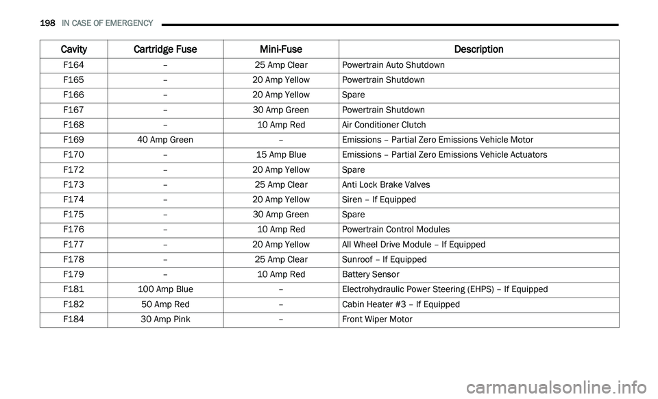
198 IN CASE OF EMERGENCY
F164 –25 Amp ClearPowertrain Auto Shutdown
F165 –20 Amp Yellow Powertrain Shutdown
F166 –20 Amp Yellow Spare
F167 –30 Amp GreenPowertrain Shutdown
F168 –10 Amp RedAir Conditioner Clutch
F169 40 Amp Green –Emissions – Partial Zero Emissions Vehicle Motor
F170 –15 Amp BlueEmissions – Partial Zero Emissions Vehicle Actuators
F172 –20 Amp Yellow Spare
F173 –25 Amp ClearAnti Lock Brake Valves
F174 –20 Amp Yellow Siren – If Equipped
F175 –30 Amp GreenSpare
F176 –10 Amp RedPowertrain Control Modules
F177 –20 Amp Yellow All Wheel Drive Module – If Equipped
F178 –25 Amp ClearSunroof – If Equipped
F179 –10 Amp RedBattery Sensor
F181 100 Amp Blue –Electrohydraulic Power Steering (EHPS) – If Equipped
F182 50 Amp Red –Cabin Heater #3 – If Equipped
F184 30 Amp Pink –Front Wiper Motor
Cavity Cartridge Fuse Mini-FuseDescription