Page 185 of 248

Driver assistance systems
● If the r
a
dar sensor is covered temporarily
with some kind of accessory, such as an ad-
ditional headlight or the like.
● When the vehicle is to be loaded on a lorry,
ferry
or train.
System limitations The Front Assist has certain physical limita-
tions
inher
ent to the system. Thus, in certain
circumstances, some of the system's reac-
tions may be inopportune from the driver's
standpoint. So pay attention in order to inter-
vene if necessary.
The following conditions may cause the Front
Assist not to react or to do so too late:
● In the first few instants of driving after
swit c
hing on the ignition, due to the system’s
initial auto-calibration.
● On taking tight bends or complex paths.
● Pressing the accelerator all the way down.
● If the Front Assist is switched off or dam-
aged.
● If the ASR h
as been disconnected or the
ESC activ
ated in Sport mode manually
››› page 158.
● If the ESC is controlling.
● If several brake lights of the vehicle or elec-
trical ly
connected trailer are damaged. ●
If the r a
dar sensor is dirty or covered.
● If there are metal objects, e.g. rails on the
roa
d or sheets used in road works.
● If the vehicle is reversing.
● If the vehicle over-accelerates.
● In case of snow or heavy rain.
● In case of narrow vehicles, such as motor-
bike
s.
● Misaligned vehicles.
● Vehicles crossing the other's path.
● Vehicles approaching in the opposite direc-
tion.
● Special loads and accessories of other ve-
hicle
s that jut out over the sides, backwards
or over the top. Start-Stop System*
Operating Fig. 192
Instrument panel: Start-Stop system
b utt
on. The Start-Stop system helps save fuel and re-
duc
e h
armf
ul and CO2 emissions.
The system is automatically switched on ev-
ery time the ignition is switched on.
The system automatically switches off the en-
gine when the vehicle is stationary, e.g. wait-
ing at traffic lights.
The current status of the Start-Stop system is
displayed on the general instrument panel
display.
Automatic engine shut down (Stop phase)
– Stop the vehicle (if necessary using the
handbrak
e). »
183
Technical data
Advice
Operation
Emergencies
Safety
Page 186 of 248

– Press the clutch.
Switc
hing the Start-Stop system on and off
The Start-Stop system can")
Operation
– Shif t
t
o neutral.
– Release the clutch pedal.
Automatic
engine start up (Start phase)
– Press the clutch.
Switc
hing the Start-Stop system on and off
The Start-Stop system can be switched on
and off by pressing the button
››› Fig. 192.
The warning lamp in the button will light up
when the system is switched off.
If the vehicle is in Stop phase when the but-
ton is pressed, the engine will start immedi-
ately.
The Start-Stop system works under complex
driving conditions that are difficult to detect
without specialist technology. The set of nec-
essary conditions for the correct operating of
the Start-Stop system are indicated below.
Conditions for automatic engine shut down
(Stop phase) ● Selector lever in neutral.
● Clutch pedal not pressed.
● Driver with seat belt fastened.
● Driver door closed.
● The bonnet closed.
● Vehicle stationary. ●
The factor
y-fitted towing bracket is not elec-
trically connected to a trailer.
● Engine at operating temperature.
● Vehicle's battery sufficiently charged.
● Vehicle not on a very steep slope
● Engine speed below 1,200 rpm.
● Vehicle battery temperature is neither too
high nor too low
.
● Sufficient brake system pressure.
● Difference between outside temperature
and set interior t
emperature not too great
● Vehicle speed since the last time the en-
gine star
ted was above 3 km/h (2 mph).
● Particulate filter not being cleaned
›››
page 168.
● Front wheels not overly turned (steering
wheel turned l
ess than three quarters of a
turn)
Conditions for engine start up (Start phase)
● Clutch pedal pressed.
● Max./min. temperature set.
● Windscreen defrost function switched on.
● High blower speed.
● Start-Stop button pressed. Conditions for automatic engine start up
without driv
er involvement
● Vehicle moving at a speed of over 3 km/h
(2 mph).
● Difference between outside temperature
and interior temper
ature is too great
● Vehicle's battery insufficiently charged.
● Insufficient brake system pressure.
If the driver se
at belt is unfastened for more
than 30 seconds in Stop phase, the engine
must be started using the ignition key.
Please observe the messages on the general
instrument panel display.
Warnings on the instrument panel display
(valid for vehicles not fitted with an informa-
tive display)
FAULT: Start-StopFault in the Start-Stop sys-
tem
START-STOP IMPOSSI-
BLEEngine cannot be auto-
matically shut down
START-STOP ACTIVEAutomatic engine shut
down (Stop phase)
SWITCH OFF IGNITIONSwitch the ignition off
START MANUALLYStart the engine manually WARNING
● If the en gine i
s switched off, neither the
brake servo nor the power steering will work. 184
Page 187 of 248

Driver assistance systems
●
Do not mo v
e the vehicle when the engine is
switched off. CAUTION
Switch off the Start-Stop system ›
››
page 169
before driving through a pool of water on the
road. Note
● The batt er
y temperature may reflect
changes in outside temperature after several
hours. If the vehicle has been stopped out-
side at temperatures below zero or in direct
sunlight, for example, the battery tempera-
ture may take several hours to reach the val-
ues required for the correct operating of the
Start-Stop system.
● If the Climatronic system is operating auto-
matica
lly, this could impair automatic engine
shut down under certain conditions. Fatigue detection (break rec-
ommend
ation)*
Intr oduction The Fatigue detection informs the driver
when their driv
in
g beh
aviour shows signs of
fatigue. WARNING
Do not let the comfort afforded by the Fatigue
detection sy s
tem tempt you into taking any
risks when driving. Take regular breaks, suffi-
cient in length when making long journeys.
● The driver always assumes the responsibil-
ity of driv
ing to their full capacity.
● Never drive if you are tired.
● The system does not detect the tiredness of
the driver in al
l circumstances. Consult the in-
formation in the section ››› page 186, System
limitations.
● In some situations, the system may incor-
rectly int
erpret an intended driving manoeu-
vre as driver tiredness.
● No warning is given in the event of the ef-
fect c
alled microsleep!
● Please observe the indications on the in-
strument p
anel and act as is necessary. Note
● Fatigue det ection h
as been developed for
driving on motorways and well paved roads
only.
● If there is a fault in the system, have it
check
ed by a specialised workshop. Function and operation
Fig. 193
On the instrument panel display: fa-
tigue det ection symbo
l
. Fatigue detection determines the driving be-
h
av
iour of
the driver when starting a journey,
making a calculation of tiredness. This is
constantly compared with the current driving
behaviour. If the system detects that the driv-
er is tired, an audible warning is given with a
sound and an optic warning is shown with a
symbol and complementary message on the
instrument panel display ››› Fig. 193. The
message on the instrument panel display is
shown for approximately 5 seconds, and de-
pending on the case, is repeated. The system
stores the last message displayed.
The message on the instrument panel display
can be switched off by pressing the button on the windscreen wiper lever or the
b
utt
on on the multi function steering
wheel
›
›
› page 23. »
185
Technical data
Advice
Operation
Emergencies
Safety
Page 188 of 248

Operation
The message can be recalled to the instru-
ment p
anel
display using the multifunction
display ›››
page 23.
Conditions of operation
Driving behaviour is only calculated on
speeds above about 65 km/h (40 mph) up to
around 200 km/h (125 mph).
Switching on and off
Fatigue detection can be activated or deacti-
vated in the Easy Connect system with the button and the
S
ET
TINGS function button
› ›
›
page 101. A mark indicates that the ad-
justment has been activated.
System limitations
The Fatigue detection has certain limitations
inherent to the system. The following condi-
tions can limit the Fatigue detection or pre-
vent it from functioning.
● At speeds below 65 km/h (40 mph)
● At speeds above 200 km/h (125 mph)
● When cornering
● On roads in poor condition
● In unfavourable weather conditions
● When a sporty driving style is employed
● In the event of a serious distraction to the
driver Fatigue det
ection will be restored when the
vehicl
e is stopped for more than 15 minutes,
when the ignition is switched off or when the
driver has unbuckled their seat belt and
opened the door.
In the event of slow driving during a long pe-
riod of time (below 65 km/h, 40 mph) the
system automatically re-establishes the tired-
ness calculation. When driving at a faster
speed the driving behaviour will be recalcula-
ted. Towing bracket device
Driv in
g w
ith a trailer
Technical requirements If your vehicle has a factory-fitted towing
brac
k
et or is equipped with a selection of
SEAT Original Accessories, it meets all the rel-
evant technical and legal requirements.
In vehicles with a towing bracket it is possi-
ble to remove the ball joint, situated (togeth-
er with the special assembly instructions) in
the housing for the spare wheel in the vehi-
cle luggage compartment ›››
page 76, Vehicle
tool kit*.
Your vehicle is fitted with a 13-pole power
socket for the electrical connection between
the trailer and the vehicle. If the trailer you
are going to use has a 7-pin connector, the
corresponding adaptor, acquired from the
SEAT Original Accessories Catalogue, can be
used.
If a towing bracket is to be retro-fitted to the
car, it must be done according to the instruc-
tions of the towing bracket manufacturer. Note
Any queries that may arise can be directed to
an authorised S EA
T dealer.186
Page 189 of 248

Towing bracket device
Trailer weight Trailer weight
The comb
ined
vehicle and trailer must be
balanced. To do so use the maximum permit-
ted towing bracket load. An insufficient
weight exerted by the trailer drawbar on the
ball joint of the towing bracket will have a
negative impact upon the response of the ve-
hicle-trailer assembly on the road.
Weight distribution
Distribute loads in the trailer so that heavy
objects are as near to the axle as possible.
Ensure that the objects do not move.
If the towing vehicle is empty and the trailer
loaded then the load distribution is incorrect.
However, if these conditions cannot be avoi-
ded, drive very slowly.
Tyre pressure values
Correct the tyre pressure in your vehicle to
“total load” ›››
page 218, Service life of
tyres.
Trailer weight
Never exceed the authorised trailer weight
under any circumstances ›››
page 223, Tech-
nical specifications .
The trailer weights listed are only applicable
for altitudes up to 1000 m above sea level.
Due to lower air density, engine power de- creases depending on the increase in alti-
tude, thi
s
also reduces climbing ability,
which requires a reduction of the weight of
the vehicle with a trailer by 10% for every
1000 m increase in altitude. The weight of
the assembly is calculated by adding the ve-
hicle weight (loaded) to the trailer weight
(loaded). Always drive with special care when
towing a trailer.
The towed load and support load information
that is displayed on the towing bracket man-
ufacturers label are only values for the verifi-
cation of the device. The correct figures for
your specific vehicle, which are usually lower
than these figures, are given in the documen-
tation of your vehicle. WARNING
● Exc eedin
g the maximum established load
per axle and the maximum towing bracket
load in addition to the maximum permitted
load or the load of the vehicle + trailer as-
sembly can cause accidents and serious inju-
ries.
● A sliding load can considerably affect the
stab
ility and safety of the vehicle + trailer as-
sembly, resulting in accidents and serious in-
juries. Driving with a trailer
Exterior mirrors
Check
whether
you can see enough of the
road behind the trailer with the standard rear
vision mirrors. If this is not the case, you
should have additional exterior mirrors fitted.
Observe the relevant statutory requirements
of the country you are in.
Headlights
Before starting a journey, also check the
headlight beam settings with the trailer
hitched up. Adjust the headlight range set-
tings if necessary ›››
page 122, Headlight
range control.
Driving speed
For your own safety do not drive faster than
the maximum permitted speed indicated on
the trailer.
At all times, immediately reduce speed if you
detect the slightest swaying movement of the
trailer. Never try to “return the trailer to a
straight position” by accelerating.
Brakes
Brake in due course! If the trailer has an over-
run brake, apply the brakes gently at first and
then, firmly. This will prevent the jerking that
can be caused by locking of trailer wheels.
Change to a lower gear in good time before »
187
Technical data
Advice
Operation
Emergencies
Safety
Page 190 of 248

Operation
descending a slope in order to take advant-
ag e of
the en
gine brake.
The trailer is incorporated into the vehicle's
anti-theft alarm system:
● When the vehicle has a factory-fitted anti-
theft al
arm and a towing bracket.
● When the trailer is electrically connected to
the vehic
le via the towing bracket socket.
● When the vehicle electrical device and the
tow
ing bracket are operational.
● When the vehicle is locked and the vehi-
cle's
anti-theft alarm device is activated.
Once the electrical connection is interrupted
with the vehicle trailer locked, the alarm
sounds.
Always switch off the vehicle anti-theft alarm
device before connecting or disconnecting a
trailer. The vehicle anti-theft alarm device
could cause the alarm to sound ››› page 116,
Anti-theft alarm*.
Engine overheating
In the event that the coolant temperature
gauge needle moves to the right section of
the scale or to the red area, immediately re-
duce speed. If the control lamp flashes on
the general instrument panel, stop the vehi-
cle and switch off the engine. Wait several
minutes and check the coolant level in the
tank ››› page 210. Please observe the following indications
›››
page 210, Control lamp .
The coolant temperature can be reduced by
switching on the heating. WARNING
● Adjus t
your speed to suit the road and traf-
fic conditions.
● An electrical installation that is connected
incorrectly
or by non-specialised personnel
can prevent the connection of the current to
the trailer and cause faults in the operation of
the electrical system throughout the entire
vehicle, leading to accidents and serious in-
jury.
● All electrical work must be carried out only
by s
pecialised services.
● Never directly connect the trailer electrical
device t
o the electrical sockets of the reverse
driving lights or other sources of electrical
current. CAUTION
● Av oid c
orners, and sudden and sharp brak-
ing.
● Once the trailing arm has been removed,
plac
e the corresponding cover on the hole of
the fastening point. This prevents dirt from
entering the hole – see the trailer system as-
sembly manual. Note
● In the event of
frequent journeys with a
trailer, we recommend also having the vehi-
cle inspected in between the service inter-
vals.
● When connecting and disconnecting the
trail
er, the handbrake must be applied.
● For technical reasons, trailers with LED re-
verse light
s cannot be incorporated into the
vehicle anti-theft alarm system. Towing bracket device
Intr oduction If the vehicle is equipped with a towing
br
ac
k
et device from the factory or is a genu-
ine SEAT accessory, it meets all national tech-
nical and legal requirements for towing.
Your vehicle is fitted with a 13-pin power
socket for the electrical connection between
the trailer and the vehicle. If the trailer is
equipped with a 7-pin connector, you can
use the corresponding adaptor, which is
available as a genuine SEAT accessory.
The towing device has a maximum vertical
load of 50 kg.
188
Page 191 of 248

Towing bracket device
WARNING
● Bef or
e driving with the ball-headed bar fit-
ted, verify its correct assembly and place-
ment in the clamping bush.
● Do not use the ball-headed bar if it is not
correctly
placed and fixed in the clamping
bush.
● Do not use the towing device for towing if it
is d
amaged or has missing parts.
● Do not modify or adapt the towing device
connection.
● Never di
sengage the ball-headed bar with
the trail
er still hitched. CAUTION
Be careful not to damage the paint on the
bumper when h andlin
g the ball-headed bar. Description
Fig. 194
Towing bracket device support for
hit c
hin
g/ball-headed bar. The ball-headed bar is detachable. It is loca-
t
ed in the s
p
are wheel well or in the spare
wheel compartment in the boot ››› page 76,
Vehicle tool kit*.
Key to ››› Fig. 194
13-pin socket
Safety flange
1 2 Clamping bush
C
l
ampin
g bush cap
Ball head cover
Ball-headed bar
Locking balls
Centred
Red marking on the manual regulator
Manual regulator
Key
Key slot cover
Red marking on the manual regulator
White marking on the ball-headed bar Note
Contact an Authorised Service Partner if you
lose y
our key. 3
4
5
6
7
8
9
10
11
12
13
14
189
Technical data
Advice
Operation
Emergencies
Safety
Page 192 of 248

Operation
Placing in service position Fig. 195
Placing in service position. Fig. 196
Service position. Before assembling, place the ball-headed bar
in ser
v
ic
e position.
– Turn key A fully in the direction of arrow
1
› ›
› Fig. 195
.
– Hold the ball-headed bar with your left
hand.
– Pu
ll manual regulator B outward in the di-
r ection of
arr
ow 2 and turn it fully in the
dir ection of
arr
ow 3 .The manual regulator will remain in this posi-
tion.
Ser
vic
e position ››› Fig. 196
● Key C is in an open position – the key ar-
r o
w points
to the “unlocked” symbol. The key
cannot be removed from the key slot.
● The D locking balls may be fully inserted
int o the body
of
the ball-headed bar by ap-
plying some pressure.
● The red E marking on the manual regula-
t or points
t
owards the white marking on the
ball-headed bar.
● Between the manual regulator and the
body of the b
all-headed bar there is a clearly
visible space of approximately 4 mm F .
Onc e the b
al
l-headed bar has been posi-
tioned like this, it will be ready to be placed
in the clamping bush. WARNING
Do not use the ball-headed bar if it cannot be
corr ectly
placed in the service position. CAUTION
The key cannot be removed from the manual
re gu
lator key slot when it is in the service po-
sition. 190
 1
1 2
2 3
3 4
4 5
5 6
6 7
7 8
8 9
9 10
10 11
11 12
12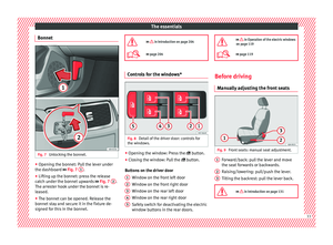 13
13 14
14 15
15 16
16 17
17 18
18 19
19 20
20 21
21 22
22 23
23 24
24 25
25 26
26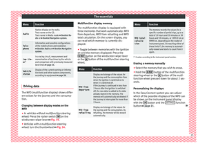 27
27 28
28 29
29 30
30 31
31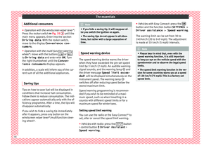 32
32 33
33 34
34 35
35 36
36 37
37 38
38 39
39 40
40 41
41 42
42 43
43 44
44 45
45 46
46 47
47 48
48 49
49 50
50 51
51 52
52 53
53 54
54 55
55 56
56 57
57 58
58 59
59 60
60 61
61 62
62 63
63 64
64 65
65 66
66 67
67 68
68 69
69 70
70 71
71 72
72 73
73 74
74 75
75 76
76 77
77 78
78 79
79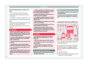 80
80 81
81 82
82 83
83 84
84 85
85 86
86 87
87 88
88 89
89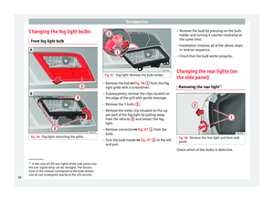 90
90 91
91 92
92 93
93 94
94 95
95 96
96 97
97 98
98 99
99 100
100 101
101 102
102 103
103 104
104 105
105 106
106 107
107 108
108 109
109 110
110 111
111 112
112 113
113 114
114 115
115 116
116 117
117 118
118 119
119 120
120 121
121 122
122 123
123 124
124 125
125 126
126 127
127 128
128 129
129 130
130 131
131 132
132 133
133 134
134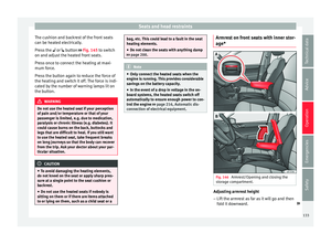 135
135 136
136 137
137 138
138 139
139 140
140 141
141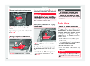 142
142 143
143 144
144 145
145 146
146 147
147 148
148 149
149 150
150 151
151 152
152 153
153 154
154 155
155 156
156 157
157 158
158 159
159 160
160 161
161 162
162 163
163 164
164 165
165 166
166 167
167 168
168 169
169 170
170 171
171 172
172 173
173 174
174 175
175 176
176 177
177 178
178 179
179 180
180 181
181 182
182 183
183 184
184 185
185 186
186 187
187 188
188 189
189 190
190 191
191 192
192 193
193 194
194 195
195 196
196 197
197 198
198 199
199 200
200 201
201 202
202 203
203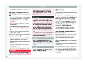 204
204 205
205 206
206 207
207 208
208 209
209 210
210 211
211 212
212 213
213 214
214 215
215 216
216 217
217 218
218 219
219 220
220 221
221 222
222 223
223 224
224 225
225 226
226 227
227 228
228 229
229 230
230 231
231 232
232 233
233 234
234 235
235 236
236 237
237 238
238 239
239 240
240 241
241 242
242 243
243 244
244 245
245 246
246 247
247