Page 81 of 248

Self-help
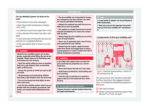
Filler tube with cap
Air c ompr
e
ssor
Tube for inflating tyres
Warning provided by tyre pressure moni-
toring system (it can also be integrated in
the compressor).
Air bleed screw (in its place, the compres-
sor may have a button).
ON/OFF switch
12 volt connector
Bottle of sealant
Spare tyre valve
The valve insert remover 1 has a gap at the
lo w
er end f
or a valve insert. The valve insert
can only be screwed or unscrewed in this
way. This also applies to its replacement part 11 .
WARNING
When inflating the wheel, the air compressor
and the inflat or t
ube may become hot.
● Protect hands and skin from hot parts.
● Do not place the hot flexible inflator tube or
hot air compr
essor on flammable material.
● Allow them to cool before storing the de-
vice.
● If
it is not possible to inflate the tyre to at
lea
st 2.0 bars (29 psi / 200 kPa), the tyre is
too badly damaged. The sealant is not in a 3
4
5
6
7
8
9
10
11 good condition to seal the tyre. Do not con-
tinue drivin
g.
Seek specialist assistance. CAUTION
Switch off the air compressor after a maxi-
mum of 8 operation
al minutes to avoid over-
heating! Before switching on the air compres-
sor again, let it cool for several minutes. Check after 10 minutes of driving
Screw the inflator tube
››
›
Fig. 84 5 again
and c hec
k
the pressure on the gauge 6 .
1.3 b ar (19 p
s
i / 130 kPa) and lower:
● Stop the vehicle! The tyre c
annot be sealed
sufficiently with the tyre mobility set.
● You should obtain professional assistance
›››
.
1.4 b ar (20 p
s
i / 140 kPa) and higher:
● Set the tyre pressure to the correct value
again.
● Car
efully resume your journey until you
reac
h the nearest specialised workshop with-
out exceeding 80 km/h (50 mph).
● Have the damaged tyre replaced. WARNING
Driving with an unsealed tyre is dangerous
and can c au
se accidents and serious injury.
● Do not continue driving if the tyre pressure
is 1.3
bar (19 psi / 130 kPa) and lower.
● Seek specialist assistance. Towing the vehicle
Introduction Read the additional information carefully
› ›
›
page 51.
Vehicles with manual gearbox can be towed
using a towbar or towrope. They can also be
towed with either the front or rear wheels lif-
ted off the road.
Vehicles with automatic gearbox can be tow-
ed using a towbar or towrope. They can also
be towed with the front wheels lifted off the
road. If the vehicle is towed with the rear
wheels lifted off the road the automatic gear-
box will be damaged!
Maximum towing speed is 50 km/h (31
mph). »
79
Technical data
Advice
Operation
Emergencies
Safety
Page 82 of 248

Emergencies
CAUTION
● Do not t o
w-start the engine. Risk of engine
damage! In vehicles with a catalytic convert-
er, fuel that has not been burned could reach
the catalytic converter and catch fire in it.
This could damage and destroy the catalytic
converter. You may use the battery from an-
other vehicle to help you start your engine
››› page 53.
● If, due to a fault, there is no oil in the gear-
box, the car m
ay only be towed with the driv-
en wheels lifted clear of the road and trans-
ported on a special vehicle transporter or
trailer.
● If normal towing is not possible or if the ve-
hicle i
s to be towed for further than 50 km,
the vehicle must be transported on a special
vehicle transporter or trailer.
● The towrope should be slightly elastic to
reduce the lo
ad on both vehicles during tow-
ing. It is advisable to use a towrope made of
synthetic fibre or similar material only.
● Do not pull too hard with the towing vehicle
and alwa
ys take care to avoid jerking the tow-
rope. When towing on a loose surface there is
always a risk of overloading and damaging
the anchorage points.
● Attach the towrope or towbar only to the
towline anc
horages or to the removable tow-
ing bracket ››› page 186, or ››› page 80. Note
● We r ec
ommend you use the towrope or tow-
bar available in the SEAT Original Accessories
programme from authorised SEAT dealers.
● Towing a vehicle requires a certain degree
of practic
al skill. Both drivers should be fa-
miliar with the technique required for towing.
Inexperienced drivers should not attempt to
tow away another vehicle or to have their ve-
hicle towed.
● Note the legal regulations concerning tow-
ing, par
ticularly those regarding the signal-
ling of the towed and towing vehicle.
● The towrope must not be twisted, as under
cert
ain circumstances this could unscrew the
front towline anchorage. Anchoring the front tow line
Fig. 85
Front bumper: towline anchorage cov-
er/fittin g. Fitting and detaching the cover
– Press on the left of the cover as indicated
by
the arr
ow ››› Fig. 85 .
– Pull on the cover to remove it from the front
bumper.
– T
o refit the cover after unscrewing the tow-
line anchorag
e, fit the cover and press
80
Page 83 of 248

Fuses and bulbs
down on its right-hand side. The cover
mu s
t
be securely engaged.
Fitting and detaching the towline anchorage
– Screw in the towline anchorage anti-clock-
wise b
y hand as far as it will go ››› Fig. 85
.
To tighten the towline anchorage, we recom-
mend using the box spanner, the towing eye
from another vehicle or a similar object that
can be inserted through the anchorage.
– Unscrew the towline anchorage by turning
it cloc
kwise. CAUTION
The towline anchorage must be screwed in as
far a s
it will go. Otherwise there is a risk of
the screw connection shearing off during
towing or tow-starting! Fuses and bulbs
F u
se
s
Introduction Due to the constant updating of vehicles,
fu
se a
ssignments based on equipment and
the use of the same fuse for various electrical
components, it is not possible to provide an
up-to-date summary of the fuse positions for
the electrical components at the time this
manual was printed. For detailed information
about the fuse positions, please consult a
technical service.
In general, a fuse can be assigned to various
electrical components. Likewise, an electrical
component can be protected by several
fuses.
Only replace fuses when the cause of the
problem has been solved. If a newly inserted
fuse blows after a short time, you must have
the electrical system checked by a special-
ised workshop as soon as possible.
Additional information and warnings:
● Working in the engine compartment
›› ›
page 204. WARNING
The high voltages in the electrical system can
give seriou s
electrical shocks, causing burns
and even death!
● Never touch the electrical wiring of the igni-
tion syst
em.
● Take care not to cause short circuits in the
electrica
l system. WARNING
Using unsuitable fuses, repairing fuses or
bridging a c urr
ent circuit without fuses can
cause a fire and serious injury.
● Never use a fuse with a higher value. Only
repl
ace fuses with a fuse of the same amper-
age (same colour and markings) and size.
● Never repair a fuse.
● Never replace a fuse by a metal strip, staple
or simil
ar. CAUTION
● To pr ev
ent damage to the vehicle's electric
system, before replacing a fuse always turn
off the ignition, the lights and all electrical
elements and remove the key from the igni-
tion.
● If you replace a fuse with higher-rating
fuse,
you could cause damage to another part
of the electrical system. » 81
Technical data
Advice
Operation
Emergencies
Safety
Page 84 of 248

Emergencies
●
Prot ect
the fuse boxes when open to pre-
vent the entry of dust or humidity as they can
damage the electrical system.
● Always carefully remove the fuse box cov-
ers and r
efit them correctly to avoid problems
with your vehicle. Note
● One c omponent m
ay have more than one
fuse.
● Several components may run on a single
fuse.
● In the
vehicle, there are more fuses than
those indicat
ed in this chapter. These should
only be changed by a specialised workshop.
● Positions not containing a fuse do not ap-
pear in the fo
llowing tables.
● Some of the equipment listed in the tables
below pert
ain only to certain versions of the
model or are optional extras.
● Please note that the above lists, while cor-
rect at
the time of printing, are subject to
change. Fuses in the dash panel
Fig. 86
Diagram of the fuse box to the
l ef
t/right
of the steering wheel Read the additional information carefully
› ›
›
page 44
Only replace fuses with a fuse of the same
amperage (same colour and markings) and
size.
Fuse placement
No.Consumer
1Left light
2Central locking, windscreen wipers, with Keyless
Access
3Ignition system relay
4Right light
5Electric windows - Driver
No.Consumer
6Central control unit - Interior lights
7Horn
8Towing bracket - Left light
9
Controls on steering column (without Keyless Ac-
cess only), engine control unit (without Keyless
Access only), automatic gearbox control unit
(without Keyless Access only), automatic gear-
box lever (without Keyless Access only), ESP
control unit (without Keyless Access only), trailer
hook control unit (without Keyless Access only),
electric power steering (without Keyless Access
only)
10Rear left window
11Headlight washer unit
12Radio and navigation display
13Preparation as taxi
14
Control lever under steering wheel, light switch,
traction locking with ignition key (automatic
transmission), headlight flasher, SmartGate con-
trol device, rain/light sensor, rear camera
15Air conditioning system control unit, automatic
gearbox selector lever, diagnostics connection
16Instrument panel
17Alarm sensor, horn
22Windscreen washer system (without Keyless Ac-
cess)
23Heated front seats 82
Page 85 of 248

Fuses and bulbsNo.Consumer
24Air conditioning fan, heating, control unit for air
conditioning, heating
26Front seat heating switch.
27Rear window wiper
29Airbag
30
Electric windows, reversing light switch, air con-
ditioning control unit, Park Assist control unit,
exterior mirror, power supply for middle button
bar, power supply for the side button bar, interi-
or mirror
31Fuel pump, radiator fan control unit, cruise con-
trol, relay coil for the windscreen and rear win-
dow washer system, switch for the lights
32Diagnostics socket, headlight range regulator,
control lever under the steering wheel, ambient
lighting regulator
33Ignition relay coil, clutch pedal switch
34Heatable washer jets of windscreen washer
36USB charging socket
37Radar
39Additional electric heating
41Rear window heater
42Electric windows - passenger
43Towing bracket - Connector contact
No.Consumer
4412 V connection in the interior, 12 V connection
in the boot
45Rear right window
46Windshield and front window washing system,
control lever under the steering wheel
47Towing bracket - Connector contact
48Towing bracket - Right hand light
49Fuel pump control unit
50Radio
51Heat for exterior mirrors
52Keyless Access
53Steering lock (Keyless Access)
54ABS/ESC control unit
56Diagnosis
59Full LED
Fuses in the engine compartment
Fig. 87
In the engine compartment: fuse box
c o
v
er - 1st variant » 83
Technical data
Advice
Operation
Emergencies
Safety
Page 86 of 248

Emergencies
Fig. 88
In the engine compartment: fuse box
c o
v
er - 2nd variant Read the additional information carefully
› ›
›
page 44
Only replace fuses with a fuse of the same
amperage (same colour and markings) and
size.
Opening the fuse box ● Open the bonnet ›››
page 204.
● Press lid locking clip upwards in the direc-
tion of the arro
w 1
› ›
› Fig. 87 o ››› Fig. 88. ●
Open the cov
er in the direction indicated
by the arrow 2 .
● Remove the plastic clip from the lid of the
f u
se bo
x.
● Replace the appropriate fuse.
● Place the plastic clip back in its original po-
sition.
● Plac
e the lid on the fuse box and press un-
til
you hear it click into place.
Fuse placement
No.Consumer
1Radiator fan
2Control unit for the glow system
3ABS/ESC control unit
4Additional electric heat - Circuit 2
5Additional electric heat - Circuit 3
6Automatic gearbox
7Engine control unit
8Front windscreen wipers
9Central control unit, battery data module
10ABS/ESC control unit
12Engine components
13Brake pedal switch
No.Consumer
14Engine components, fuel coil relay, radiator fan,
coolant pump
15Engine control unit
16Starter motor
17Engine control unit
18Engine components, additional electric heat re-
lay coils
19Lambda probe
20Control devices for the glow system, heating of
the sump fan Changing bulbs
Intr oduction Read the additional information carefully
› ›
›
page 45.
Depending on how equipped the vehicle is,
there are different sets of headlights and tail
lights:
● Halogen main headlights (double head-
light).
● Full-LED main headlights*.
● Rear bulb light.
● LED rear light*.
84
Page 87 of 248

Fuses and bulbs
Full-LED headlight system*
F u
l
l-LED headlights handle all light functions
(daylight, side light, turn signal, dipped
beam and route light) with light emitting di-
odes (LEDs) as a light source.
Full-LED headlights are designed to last the
lifetime of the car and light bulbs cannot be
replaced. In case of headlight failure, go to
an authorised workshop to have it replaced.
Double headlight bulb change
Changing bulbs requires a certain degree of
practical skill. If in doubt, we recommend you
have defective bulbs changed by a special-
ised service or, in case of an emergency,
seek professional assistance.
● Switch off the ignition and all of the lights
before c
hanging a bulb.
● Do not touch the glass part of the bulb with
your bar
e hands. The fingerprints left on the
glass will vaporise as a result of the heat gen-
erated by the bulb, reducing bulb life and
causing condensation on the reflector sur-
face, thus reducing effectiveness.
● A bulb must only be replaced by one of the
same type. The type i
s indicated on the bulb,
either on the glass part or on the base.
● There is a storage area for the bulb box in
the spar
e wheel well or below the carpet in
the luggage compartment. WARNING
● Tak e p
articular care when working on com-
ponents in the engine compartment if the en-
gine is warm. Risk of burns.
● Bulbs are highly sensitive to pressure. The
glas
s can break when you touch the bulb,
causing injury.
● When changing bulbs, please take care not
to injure
yourself on sharp parts in the head-
light housing. CAUTION
● Remo v
e the ignition key before working on
the electric system. Otherwise, a short circuit
could occur.
● Switch off the lights and the parking light
before c
hanging a bulb. For the sake of the environment
Please ask your specialist retailer how to dis-
pose of u
sed bulbs in the proper manner. Note
● Dependin g on w
eather conditions (cold or
wet), the front lights, the fog lights, the rear
lights and the turn signals may be temporari-
ly misted. This has no influence on the useful
life of the lighting system. By switching on
the lights, the area through which the beam
of light is projected will quickly be demisted.
However, the edges may continue to be mis-
ted. ●
Ple a
se check at regular intervals that all
lighting (especially the exterior lighting) on
your vehicle is functioning properly. This is
not only in the interest of your own safety,
but also that of all other road users.
● Before changing a bulb, make sure you
have the c
orrect new bulb.
● Do not touch the glass part of the bulb with
your bar
e hands, use a cloth or paper towel
instead. Otherwise, the fingerprints left on
the glass will vaporise as a result of the heat
generated by the bulb, they will be deposited
on the reflector and damage its surface. Double headlight bulbs
Fig. 89
Main headlight bulbs. Installation position of double headlight
b
u
l
bs
Side lights
Main beam headlights »
A B
85
Technical data
Advice
Operation
Emergencies
Safety
Page 88 of 248

Emergencies
Dipped beam headlights
T urn s
ign
al lights
Daylight
Changing side light bulbs Fig. 90
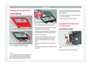
Changing side light bulbs. –
Raise the bonnet.
– Remove the protective cover ›
› ›
Fig. 90.
– Remove the bulb holder ›››
Fig. 90 1 by
p u
l
ling it outwards.
– Remove the bulb by pulling it out and fit
the new one.
– Installation involves all of the above steps
in rever
se sequence.
– Fit the protective cover. Make sure that the
cov
er fits correctly on the housing during
operation.
– Check whether the new bulb is working.
C D
E Changing main beam headlight bulb
Fig. 91
Changing main beam headlight
b u
l
bs. –
Raise the bonnet.
– Remove the protective cover.
– Remove connector ››
›
Fig. 91 1 by pulling
outw ar
d.
– Extr
act the bulb and fit the replacement so
that it
fits correctly into the recess on the
reflector.
– Installation involves all of the above steps
in rever
se sequence.
– Fit the protective cover. Make sure that the
cov
er fits correctly on the housing during
operation.
– Check whether the new bulb is working. Changing dipped beam light bulbs
Fig. 92
Changing dipped beam headlight
b u
l
bs: wheel housing. Fig. 93
Changing dipped beam headlight
b u
l
bs. –
Turn the wheel for access to the wheel
hou s
in
g cover and remove the cover
››› Fig. 92.
– Remove the protective cover from the head-
light ››
› Fig. 93.
86