2017 MERCEDES-BENZ GLA SUV ESP
[x] Cancel search: ESPPage 218 of 369
The multifunction display shows the
Check
Check
trailer hitch lock
trailer hitch lock display message until
the ball coupling is engaged.
X Remove the protective cap from the ball cou-
pling and store it in a safe place.
X Make sure that the ball of the ball coupling is
clean and that it is either greased or dry
(grease free), depending on the instructions
for the trailer.
Folding in the ball coupling G
WARNING
If you release the ball coupling or it does not
engage correctly when folding in, it will swing out. Within pivoting range of the ball coupling,
there is an increased risk of an accident and
injury.
Only release the ball coupling if the pivoting
range is unobstructed. Always make sure that the ball coupling engages when folding in.
i Fold the ball coupling in if you are not using
the trailer tow hitch.
X Make sure that the vehicle is stationary and
the trailer cables are disconnected.
X Place the protective cap on the ball coupling.
i The release wheel is located behind the left-
hand side trim panel in the luggage compart- ment.
X To open the cover: turn handle:anti-
clockwise, then fold down and remove
cover ;.
X Pull out release wheel =.
X Turn release wheel =anti-clockwise as far as
it will go.
The ball coupling disengages and folds out
behind the rear bumper. Indicator lamp ?
flashes.
X Press the ball coupling until it engages audibly
behind the bumper.
The indicator lamp on the release knob and
the message in the multifunction display go
out. Coupling up a trailer
X Make sure that the transmission is in position
j.
X Apply the electric parking brake.
X Position the trailer on a level surface behind
the vehicle.
X Couple up the trailer.
X Establish the electrical connection between
the vehicle and the trailer.
X Check that the trailer lighting system is work-
ing.
A connected trailer is only detected when the
electrical connection is established correctly
and when the lighting system is working prop- erly. The function of other systems, such as
ESP ®
or PARKTRONIC also depends on this. Uncoupling a trailer
G
WARNING
If you uncouple a trailer with an engaged over- run brake, you could trap your hand between
the vehicle and the trailer drawbar. This poses a risk of injury.
Do not uncouple a trailer with an engaged
overrun brake.
! Do not disconnect a trailer with an engaged
overrun brake. Otherwise, your vehicle could
be damaged by the rebounding of the overrun brake.
! Remove the installed adapter cable before
folding in the ball coupling. Otherwise, dam-
age may occur to the rear bumper and the
adapter cable.
X Make sure that the transmission is in position
P.
X Apply the electric parking brake.
X Secure the trailer against rolling away.
X Remove the trailer cable and decouple the
trailer. Trailer power supply
! You can connect accessories to the perma-
nent power supply up to a maximum of 240 W. Towing a trailer
215Driving and parking Z
Page 219 of 369
You cannot charge a trailer battery using the
power supply.
When it leaves the factory, your vehicle's trailer
socket is equipped with a permanent power
supply and a power supply that is switched on
via the ignition lock.
The permanent power supply is supplied via
trailer socket pin 9.
The power supply that is switched on via the
ignition lock is supplied via trailer socket pin 10.
The trailer's permanent power supply is
switched off in the event of low vehicle supply
voltage and after six hours at the latest.
You can find more information about fitting the
trailer electrics at a qualified specialist work-
shop.
X To switch the connected power supply on
or off: turn the key to position 2or 0respec-
tively (Y page 144). Failure check for LEDs
If LED lamps are fitted in the trailer, a malfunc-
tion message may appear in the multifunction
display even if there is no fault. The reason for
the error message may be that the current has
fallen below the minimum of 50 mA.
To ensure reliable operation of the failure indi-
cator, each LED chain in the trailer lighting must
be guaranteed a minimum current of 50 mA. Trailer with 7-pin connector
General notes Trailer with 7-pin connector:
you can connect
to the 13-pin socket on the ball coupling using
an adapter or, if necessary, an adapter cable.
Both can be obtained at a qualified specialist
workshop.
Fitting the adapter !
Make sure that there is sufficient cable play
so that the cable cannot become detached
when cornering.
! Remove the installed adapter cable before
folding in the ball coupling. Otherwise, dam-
age may occur to the rear bumper and the
adapter cable. X
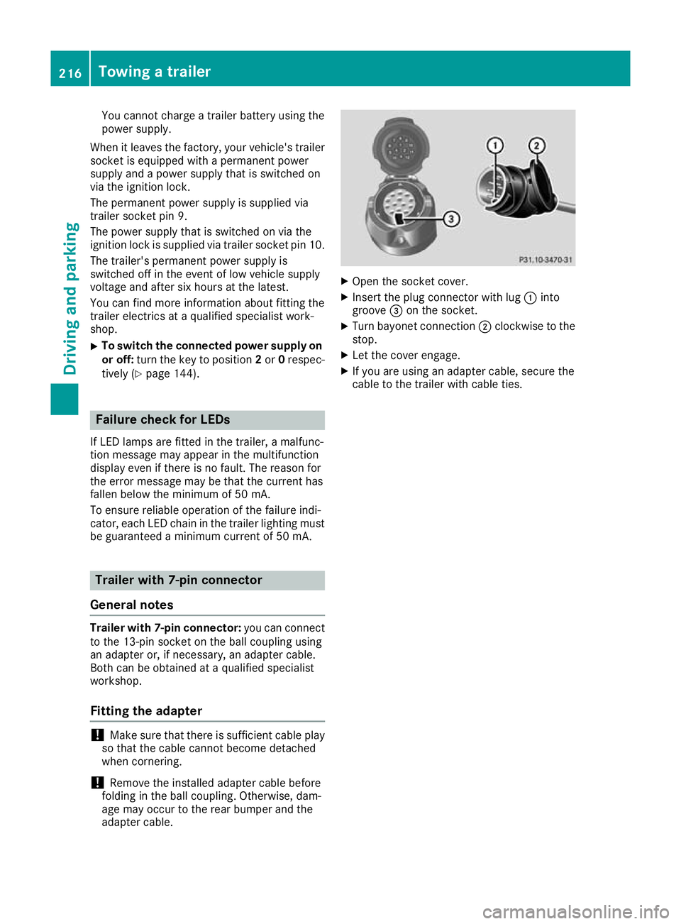
Open the socket cover.
X Insert the plug connector with lug :into
groove =on the socket.
X Turn bayonet connection ;clockwise to the
stop.
X Let the cover engage.
X If you are using an adapter cable, secure the
cable to the trailer with cable ties. 216
Towing a trailerDriving and parking
Page 229 of 369
Redialling
The on-board computer saves the last names or
numbers dialled in the redial memory.
X Press the =or; button on the steering
wheel to select the Tel
Telmenu.
X Press the 6button to switch to the redial
memory.
X Press the 9or: button to select the
desired name or number.
X Press the 6ora button to start dial-
ling.
or X If you do not want to make the call: press
the ~ or% button. Assistance menu
Introduction Depending on the equipment fitted in the vehi-
cle, you have the following options in the
Assist.
Assist. menu:
R Showing the assistance graphic
(Y page 226)
R Activating/deactivating the Traffic Sign
Assist message function (Y page 226)
R Deactivating/activating ESP ®
(except
Mercedes‑AMG vehicles) (Y page 227)
R Activating/deactivating Active Brake Assist
(Y page 227)
R Activating/deactivating ATTENTION ASSIST
(Y page 227)
R Activating/deactivating Blind Spot Assist
(Y page 227)
R Activating/deactivating Lane Keeping Assist
(Y page 227) Showing the assistance graphic X
Press the =or; button on the steering
wheel to select the Assist. Assist.menu.
X Press 9or: to select Assistance
Assistance
graphic
graphic.
X Press ato confirm.
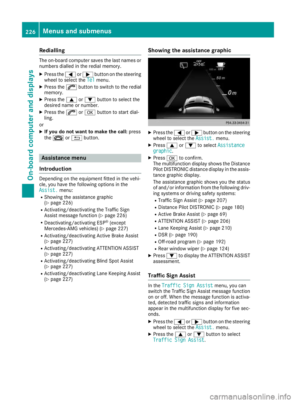
The multifunction display shows the Distance
Pilot DISTRONIC distance display in the assis- tance graphic display.
The assistance graphic shows you the status
of and/or information from the following driv-
ing systems or driving safety systems:
R Traffic Sign Assist (Y page 207)
R Distance Pilot DISTRONIC (Y page 180)
R Active Brake Assist (Y page 69)
R ATTENTION ASSIST (Y page 206)
R Lane Keeping Assist (Y page 210)
R DSR (Y page 190)
R Off-road program (Y page 192)
R Rear window wiper (Y page 124)
X Press :to display the ATTENTION ASSIST
assessment.
Traffic Sign Assist In the
Traffic Sign Assist Traffic Sign Assist menu, you can
switch the Traffic Sign Assist message function
on or off. When the message function is activa-
ted, detected traffic signs and information
appear in the multifunction display for five sec-
onds.
X Press the =or; button on the steering
wheel to select the Assist.
Assist. menu.
X Press the 9or: button to select
Traffic Sign Assist Traffic Sign Assist. 226
Menus and submenusOn-board computer and displays
Page 230 of 369
X
Press ato confirm.
The current selection appears.
X To activate/deactivate the message func-
tion: press aagain.
Further information about Traffic Sign Assist
(Y page 207).
Deactivating/activating ESP ®Observe the important safety notes on ESP
®
(Y page 72). G
WARNING
If you deactivate ESP ®
, ESP ®
no longer sta-
bilises the vehicle. There is an increased risk
of skidding and an accident.
Only deactivate ESP ®
in the situations descri-
bed in the following.
It may be best to deactivate ESP ®
in the follow-
ing situations:
R when using snow chains
R in deep snow
R on sand or gravel
Deactivating/activating ESP ®
on Mercedes-
AMG vehicles (Y page 73).
For further information about ESP ®
, see
(Y page 72).
X Start the engine.
X Press the =or; button on the steering
wheel to select the Assist. Assist.menu.
X Press 9or: to select ESP ESP.
X Press ato confirm.
The current selection appears.
X To activate/deactivate: pressaagain.
ESP ®
is deactivated if the åwarning lamp
in the instrument cluster lights up continu-
ously when the engine is running.
If the ÷ andå warning lamps light up
continuously, ESP ®
is not available due to a mal-
function.
Observe the information on warning lamps
(Y page 269).
Observe the information on display messages
(Y page 235). Activating/deactivating Active Brake
Assist X
Press the =or; button on the steering
wheel to select the Assist. Assist.menu.
X Press the 9or: button to select
Brake Assist
Brake Assist.
X Press ato confirm.
The current selection appears.
X To activate/deactivate: pressaagain.
When Active Brake Assist is deactivated, the
æ symbol appears in the multifunction dis-
play in the assistance graphic display.
Further information on Active Brake Assist
(Y page 69).
Activating/deactivating ATTENTION
ASSIST X
Press the =or; button on the steering
wheel to select the Assist. Assist.menu.
X Press the 9or: button to select
Attention Assist Attention Assist.
X Press ato confirm.
The current selection appears.
X Press ato confirm.
X Press the :or9 button to set Off
Off,
Standard
Standard orSensitive
Sensitive.
X Press the abutton to save the setting.
When ATTENTION ASSIST is deactivated, the
é symbol appears in the multifunction dis-
play in the assistance graphic display.
For further information about ATTENTION
ASSIST, see (Y page 206).
Activating/deactivating Blind Spot
Assist X
Press the =or; button on the steering
wheel to select the Assist. Assist.menu.
X Press the 9or: button to select
Blind Spot Assist
Blind Spot Assist.
X Press ato confirm.
The current selection appears.
X To activate/deactivate: pressaagain.
Further information about Blind Spot Assist
(Y page 209). Menus and submenus
227On-board computer and displays Z
Page 233 of 369
Heating
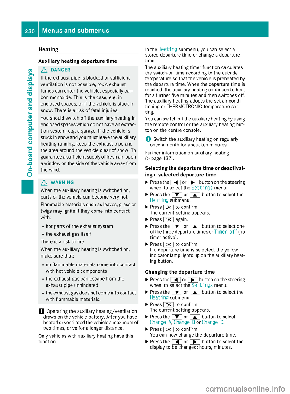
Auxiliary heating departure time
G
DANGER
If the exhaust pipe is blocked or sufficient
ventilation is not possible, toxic exhaust
fumes can enter the vehicle, especially car-
bon monoxide. This is the case, e.g. in
enclosed spaces, or if the vehicle is stuck in
snow. There is a risk of fatal injuries.
You should switch off the auxiliary heating in
enclosed spaces which do not have an extrac- tion system, e.g. a garage. If the vehicle is
stuck in snow and you must leave the auxiliary
heating running, keep the exhaust pipe and
the area around the vehicle clear of snow. To guarantee a sufficient supply of fresh air, open
a window on the side of the vehicle away from the wind. G
WARNING
When the auxiliary heating is switched on,
parts of the vehicle can become very hot.
Flammable materials such as leaves, grass or twigs may ignite if they come into contact
with:
R hot parts of the exhaust system
R the exhaust gas itself
There is a risk of fire.
When the auxiliary heating is switched on,
make sure that:
R no flammable materials come into contact
with hot vehicle components
R the exhaust gas can escape from the
exhaust pipe unhindered
R the exhaust gas does not come into contact
with flammable materials.
! Operating the auxiliary heating/ventilation
draws on the vehicle battery. After you have
heated or ventilated the vehicle a maximum of two times, drive for a longer distance.
Only vehicles with auxiliary heating have this
function. In the
Heating Heating submenu, you can select a
stored departure time or change a departure
time.
The auxiliary heating timer function calculates
the switch-on time according to the outside
temperature so that the vehicle is preheated by the departure time. When the departure time isreached, the auxiliary heating continues to heat
for a further five minutes and then switches off. The auxiliary heating adopts the set air condi-
tioning or THERMOTRONIC temperature set-
ting.
You can switch off the auxiliary heating by using
the remote control or the auxiliary heating but-
ton on the centre console.
i Switch the auxiliary heating on regularly
once a month for about ten minutes.
Further information on auxiliary heating
(Y page 137).
Selecting the departure time or deactivat-
ing a selected departure time
X Press the =or; button on the steering
wheel to select the Settings
Settings menu.
X Press the :or9 button to select the
Heating Heating submenu.
X Press ato confirm.
The current setting appears.
X Press aagain.
X Press the :or9 button to select one
of the three departure times or Timer
Timeroff
off(no
timer active).
X Press ato confirm.
If a departure time is selected, the yellow
indicator lamp lights up on the auxiliary heat- ing button.
Changing the departure time
X Press the =or; button on the steering
wheel to select the Settings Settingsmenu.
X Press the :or9 button to select the
Heating
Heating submenu.
X Press ato confirm.
The current setting appears.
X Press the :or9 button to select
Change A
Change A, Change B
Change BorChange C
Change C.
X Press ato confirm.
You can now change the departure time.
X Press the =or; button to select the
display to be changed: hours, minutes. 230
Menus and submenusOn-board computer and displays
Page 235 of 369
ture
?and Bare displayed in white in the
multifunction display.
If the multifunction display shows oil temper- ature ?orB in blue, the engine or the
transmission are not yet at normal operating
temperature. Avoid using the full output of the engine during this time.
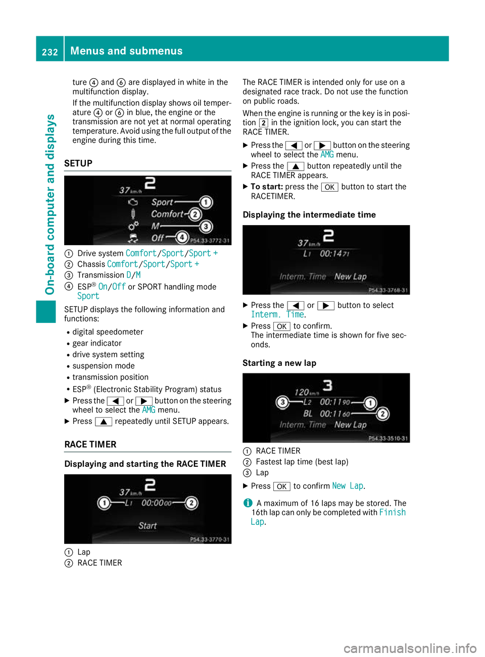
SETUP :
Drive system Comfort Comfort/Sport
Sport/Sport +
Sport +
; Chassis Comfort
Comfort/Sport Sport/Sport +
Sport +
= Transmission D
D/MM
? ESP ®
On
On/ Off
Off or SPORT handling mode
Sport
Sport
SETUP displays the following information and
functions:
R digital speedometer
R gear indicator
R drive system setting
R suspension mode
R transmission position
R ESP ®
(Electronic Stability Program) status
X Press the =or; button on the steering
wheel to select the AMG
AMG menu.
X Press 9repeatedly until SETUP appears.
RACE TIMER Displaying and starting the RACE TIMER
:
Lap
; RACE TIMER The RACE TIMER is intended only for use on a
designated race track. Do not use the function
on public roads.
When the engine is running or the key is in posi- tion 2in the ignition lock, you can start the
RACE TIMER.
X Press the =or; button on the steering
wheel to select the AMG AMGmenu.
X Press the 9button repeatedly until the
RACE TIMER appears.
X To start: press the abutton to start the
RACETIMER.
Displaying the intermediate time X
Press the =or; button to select
Interm. Time Interm. Time.
X Press ato confirm.
The intermediate time is shown for five sec-
onds.
Starting a new lap :
RACE TIMER
; Fastest lap time (best lap)
= Lap
X Press ato confirm New Lap
New Lap.
i A maximum of 16 laps may be stored. The
16th lap can only be completed with Finish
Finish
Lap
Lap . 232
Menus and submenusOn-board computer and displays
Page 237 of 369
Display messages
Introduction
General notes Display messages appear in the multifunction display.
Display messages with graphic symbols are simplified in the Owner's Manual and may differ from
the symbols in the multifunction display.
Please respond in accordance with the display messages and follow the additional notes in this
Owner's Manual.
Certain display messages are accompanied by an audible warning tone or a continuous tone.
When the ignition is switched off, all display messages are deleted apart from some high-priority
display messages. Once the causes of the high-priority display messages have been rectified, these
display messages are deleted as well.
When you stop and park the vehicle, please observe the notes on:
R HOLD function (Y page 186)
R Parking (Y page 166)
Hiding display messages X
Press the aor% button on the steering wheel.
The multifunction display hides the display message.
The multifunction display shows high-priority display messages in red. Some high-priority display
messages cannot be hidden.
The multifunction display shows these messages continuously until the causes for the messages
have been remedied.
Message memory The on-board computer saves certain display messages in the
message memory. You can call up
the display messages:
X Press the =or; button on the steering wheel to select the Service
Service menu.
If there are display messages, the multifunction display shows 2 messages
2 messages, for example.
X Press the 9or: button to select the entry, e.g. 2 messages
2 messages.
X Press ato confirm.
X Press the 9or: button to scroll through the display messages. 234
Display
messagesOn-board computer and displays
Page 238 of 369
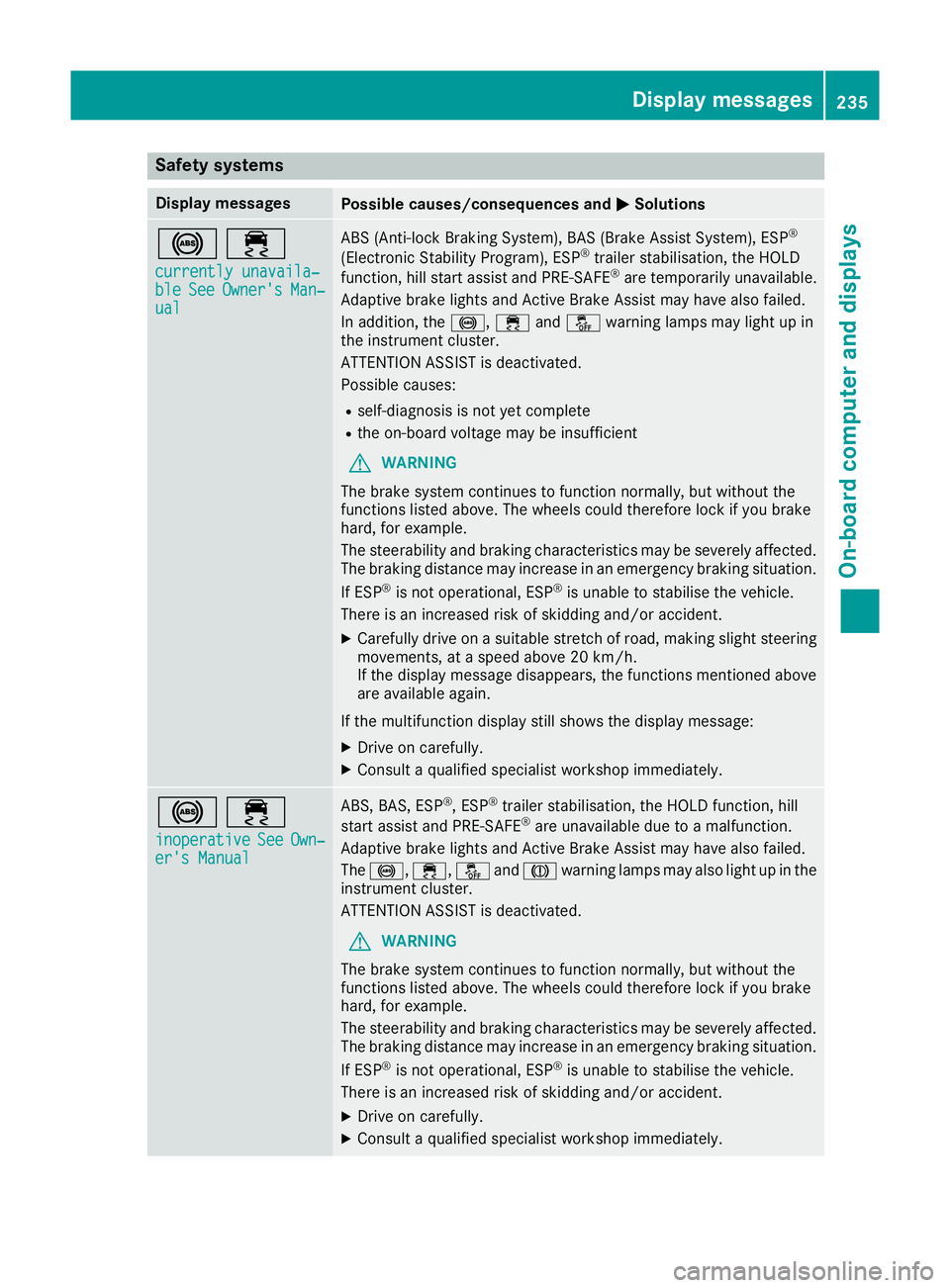
Safety systems
Display messages
Possible causes/consequences and
M
MSolutions !÷
currently unavaila‐
currently unavaila‐
ble ble See
SeeOwner's
Owner's Man‐
Man‐
ual
ual ABS (Anti-lock Braking System), BAS (Brake Assist System), ESP
®
(Electronic Stability Program), ESP ®
trailer stabilisation, the HOLD
function, hill start assist and PRE-SAFE ®
are temporarily unavailable.
Adaptive brake lights and Active Brake Assist may have also failed.
In addition, the !,÷andå warning lamps may light up in
the instrument cluster.
ATTENTION ASSIST is deactivated.
Possible causes:
R self-diagnosis is not yet complete
R the on-board voltage may be insufficient
G WARNING
The brake system continues to function normally, but without the
functions listed above. The wheels could therefore lock if you brake
hard, for example.
The steerability and braking characteristics may be severely affected. The braking distance may increase in an emergency braking situation.
If ESP ®
is not operational, ESP ®
is unable to stabilise the vehicle.
There is an increased risk of skidding and/or accident.
X Carefully drive on a suitable stretch of road, making slight steering
movements, at a speed above 20 km/h.
If the display message disappears, the functions mentioned above
are available again.
If the multifunction display still shows the display message: X Drive on carefully.
X Consult a qualified specialist workshop immediately. !÷
inoperative inoperative See
See Own‐
Own‐
er's Manual
er's Manual ABS, BAS, ESP
®
, ESP ®
trailer stabilisation, the HOLD function, hill
start assist and PRE-SAFE ®
are unavailable due to a malfunction.
Adaptive brake lights and Active Brake Assist may have also failed.
The !, ÷,åandJ warning lamps may also light up in the
instrument cluster.
ATTENTION ASSIST is deactivated.
G WARNING
The brake system continues to function normally, but without the
functions listed above. The wheels could therefore lock if you brake
hard, for example.
The steerability and braking characteristics may be severely affected. The braking distance may increase in an emergency braking situation.
If ESP ®
is not operational, ESP ®
is unable to stabilise the vehicle.
There is an increased risk of skidding and/or accident.
X Drive on carefully.
X Consult a qualified specialist workshop immediately. Display messages
235On-board computer and displays Z