2017 MERCEDES-BENZ GLA SUV load capacity
[x] Cancel search: load capacityPage 291 of 369

Loading guidelines
G
WARNING
If objects, luggage or loads are not secured or not secured sufficiently, they could slip, tip
over or be flung around and thereby hit vehicle
occupants. There is a risk of injury, especially when braking or abruptly changing directions.
Always store objects so that they cannot be
flung around. Secure objects, luggage or
loads against slipping or tipping before the
journey. G
WARNING
Combustion engines emit poisonous exhaust
gases such as carbon monoxide. If the tailgate is open when the engine is running, particu-
larly if the vehicle is moving, exhaust fumes
could enter the passenger compartment.
There is a risk of poisoning.
Turn off the engine before opening the tail-
gate. Never drive with the tailgate open. G
WARNING
The exhaust tail pipe and tail pipe trim can
become very hot. If you come into contact
with these parts of the vehicle, you could burn
yourself. There is a risk of injury.
Always be particularly careful around the
exhaust tail pipe and the tail pipe trim. Allow
these components to cool down before touch-
ing them.
The handling characteristics of a laden vehicle
are dependent on the distribution of the load
within the vehicle.
Observe the following notes on loading and
transporting a load:
R never exceed the maximum permissible gross
vehicle weight or the permissible axle loads
for the vehicle (including occupants).
R the luggage compartment is the preferred
place to store objects.
R position heavy loads as far forwards as pos-
sible and as low down in the luggage com-
partment as possible. R
the load must not protrude above the upper
edge of the seat backrests.
R always place the load against the rear or front
seat backrests. Make sure that the seat
backrests are securely locked into place.
R always place the load behind unoccupied
seats if possible.
R use the lashing eyelets and the luggage nets
to transport loads and luggage.
R only use lashing eyelets and fastening com-
ponents that are suitable for the weight and
size of the load.
R the maximum load capacity of the stowage
well under the luggage compartment floor is
25 kg.
R secure the load with sufficiently strong and
wear-resistant lashing material. Pad sharp
edges for protection.
! Do not position the load on one part of the
folding luggage compartment floor only. The
maximum load capacity of the folding luggage compartment floor is 100 kg. Spread the
weight evenly to avoid damaging the luggage
compartment floor. Place a solid board under the load if necessary. Please note that the
load on the luggage compartment floor will be increased when the load is lashed down. Stowage areas
Stowage compartments
Important safety notes G
WARNING
If you transport objects in the vehicle interior and these are not adequately secured, they
could slip or be flung around and thereby
strike vehicle occupants. In addition, cup
holders, open stowage spaces and mobile
phone brackets may not always be able to
hold the objects placed in them in the event of an accident. There is a risk of injury, particu-
larly in the event of sharp braking or sudden
changes of direction. 288
Stowage areasStowing and features
Page 294 of 369
Observe the loading guidelines (Y
page 288)
and the safety notes regarding stowage spaces
(Y page 288). Folding backrest on the front-
passenger seat
G
WARNING
If the backrest of the co-driver's seat is folded forward, passengers in the rear compartment
could collide with parts of the seat mecha-
nism, particularly in the event of an accident,
heavy braking or sudden changes of direction.
There is a risk of injury.
If another person is travelling in the vehicle
when the backrest of the co-driver's seat is
folded forward, this person must sit on the
rear seat behind the driver.
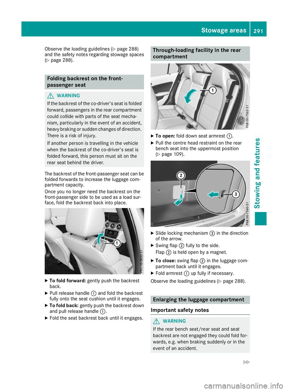
The backrest of the front-passenger seat can be
folded forwards to increase the luggage com-
partment capacity.
Once you no longer need the backrest on the
front-passenger side to be used as a load sur-
face, fold the backrest back into place. X
To fold forward: gently push the backrest
back.
X Pull release handle :and fold the backrest
fully onto the seat cushion until it engages.
X To fold back: gently push the backrest down
and pull release handle :.
X Fold the seat backrest back until it engages. Through-loading facility in the rear
compartment
X
To open: fold down seat armrest :.
X Pull the centre head restraint on the rear
bench seat into the uppermost position
(Y page 109). X
Slide locking mechanism =in the direction
of the arrow.
X Swing flap ;fully to the side.
Flap ;is held open by a magnet.
X To close: swing flap ;in the luggage com-
partment back until it engages.
X Fold armrest :up fully if necessary.
Observe the loading guidelines (Y page 288). Enlarging the luggage compartment
Important safety notes G
WARNING
If the rear bench seat/rear seat and seat
backrest are not engaged they could fold for- wards, e.g. when braking suddenly or in the
event of an accident. Stowage areas
291Stowing and features
Z
Page 295 of 369
R
The vehicle occupant would thereby be
pushed into the seat belt by the rear bench
seat/rear seat or by the seat backrest. The
seat belt cannot protect as intended and
could result in additional injury.
R Objects or loads in the boot/luggage com-
partment cannot be restrained by the seat
backrest.
This poses an increased risk of injury.
Before every trip, make sure that the seat
backrests and the rear bench seat/rear seat
are engaged before every trip.
! Before folding the backrest in the rear com-
partment forwards, make sure that the rear
compartment armrest and the cupholder are
folded in. They may otherwise be damaged.
Observe the loading guidelines (Y page 288).
The left-hand and right-hand rear seat backrests can be folded forwards separately to increase
the luggage compartment capacity.
Notes on using the luggage compart-
ment Making the best use of your luggage compart-
ment:
R You can increase the load capacity by adjust-
ing the backrest to the cargo position
(Y page 293).
R The load area can be lengthened by folding
forward the folding backrest of the front-
passenger seat (Y page 291) and the corre-
sponding backrest in the rear. Folding the rear seat backrest forwards
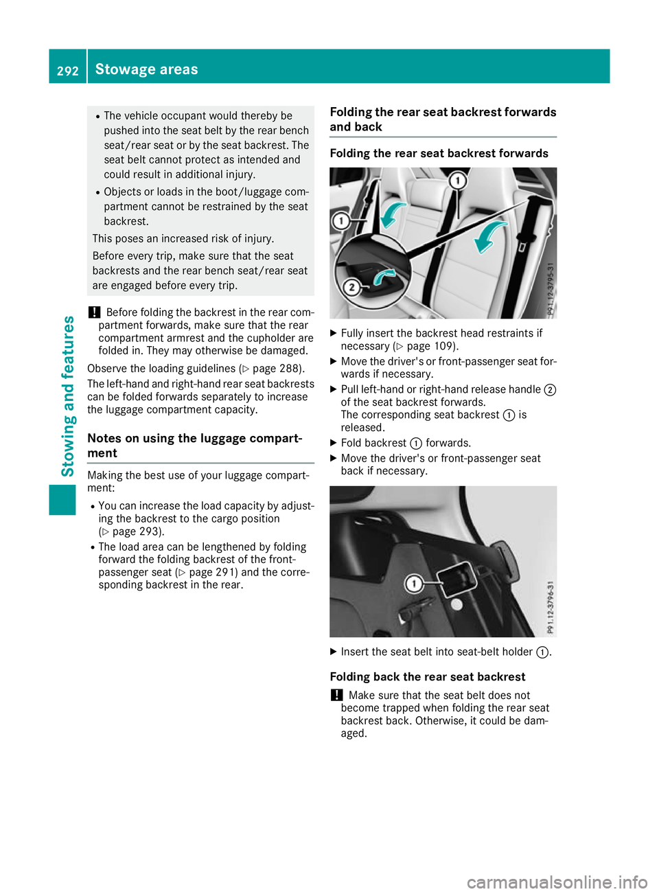
and back Folding the rear seat backrest forwards
X
Fully insert the backrest head restraints if
necessary (Y page 109).
X Move the driver's or front-passenger seat for-
wards if necessary.
X Pull left-hand or right-hand release handle ;
of the seat backrest forwards.
The corresponding seat backrest :is
released.
X Fold backrest :forwards.
X Move the driver's or front-passenger seat
back if necessary. X
Insert the seat belt into seat-belt holder :.
Folding back the rear seat backrest
! Make sure that the seat belt does not
become trapped when folding the rear seat
backrest back. Otherwise, it could be dam-
aged. 292
Stowage areasStowing and features
Page 298 of 369
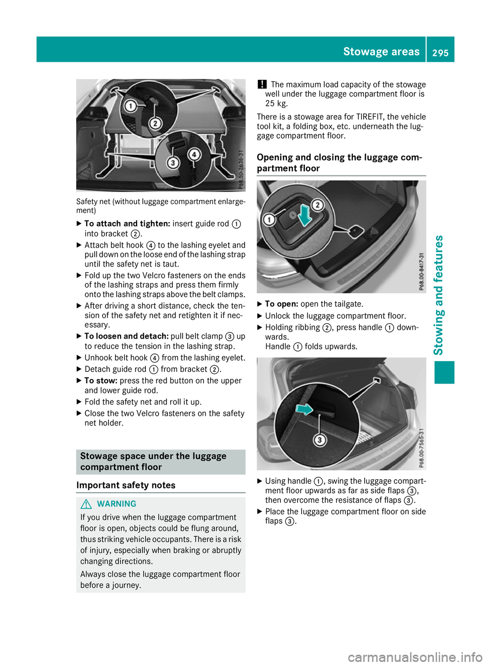
Safety net (without luggage compartment enlarge-
ment)
X To attach and tighten: insert guide rod:
into bracket ;.
X Attach belt hook ?to the lashing eyelet and
pull down on the loose end of the lashing strap until the safety net is taut.
X Fold up the two Velcro fasteners on the ends
of the lashing straps and press them firmly
onto the lashing straps above the belt clamps.
X After driving a short distance, check the ten-
sion of the safety net and retighten it if nec-
essary.
X To loosen and detach: pull belt clamp=up
to reduce the tension in the lashing strap.
X Unhook belt hook ?from the lashing eyelet.
X Detach guide rod :from bracket ;.
X To stow: press the red button on the upper
and lower guide rod.
X Fold the safety net and roll it up.
X Close the two Velcro fasteners on the safety
net holder. Stowage space under the luggage
compartment floor
Important safety notes G
WARNING
If you drive when the luggage compartment
floor is open, objects could be flung around,
thus striking vehicle occupants. There is a risk of injury, especially when braking or abruptly
changing directions.
Always close the luggage compartment floor
before a journey. !
The maximum load capacity of the stowage
well under the luggage compartment floor is
25 kg.
There is a stowage area for TIREFIT, the vehicle tool kit, a folding box, etc. underneath the lug-
gage compartment floor.
Opening and closing the luggage com-
partment floor X
To open: open the tailgate.
X Unlock the luggage compartment floor.
X Holding ribbing ;, press handle :down-
wards.
Handle :folds upwards. X
Using handle :, swing the luggage compart-
ment floor upwards as far as side flaps =,
then overcome the resistance of flaps =.
X Place the luggage compartment floor on side
flaps =. Stowage areas
295Stowing and features Z
Page 299 of 369
Roof carrier
Important safety notes G
WARNING
When a load is transported on the roof, the
vehicle's centre of gravity rises and the han-
dling changes. If you exceed the maximum
roof load, the handling as well as steering and braking characteristics are severely affected.
There is a risk of an accident.
Always observe the maximum roof load and
adapt your driving style.
! Mercedes-Benz recommends that you only
use roof carriers that have been tested and
approved for Mercedes-Benz vehicles. This
helps to prevent damage to the vehicle.
Position the load on the roof carrier in such a way that the vehicle will not sustain damage
even when it is in motion.
Ensure that, depending on the vehicle's
equipment, you can raise the panorama slid-
ing sunroof fully and open the tailgate fully
when the roof carrier is fitted.
You will find information on the maximum roof
load in the "Technical data" section
(Y page 358).
An incorrectly secured roof carrier or roof load
may become detached from the vehicle. You
must therefore ensure that you observe the roof
carrier manufacturer's installation instructions.
Attaching the roof carrier X
Secure the roof carrier to the roof rails. In
doing so, observe the manufacturer's instal-
lation instructions. Features
Cup holders
Important safety notes G
WARNING
The cup holder cannot secure a drinks con-
tainer in place during a journey. If you use a
cup holder during a journey, the drinks con- tainer could be flung around and liquid could
be spilt. Vehicle occupants could come into
contact with the liquid and, in particular, be
scalded by hot liquid. You could be distracted
from the traffic situation and lose control of
the vehicle. There is a risk of an accident and
injury.
Only use the cup holder when the vehicle is
stationary. Only place containers of a suitable size in the cup holder. Seal the container, in
particular when it contains hot liquid. G
WARNING
If you transport objects in the vehicle interior and these are not adequately secured, they
could slip or be flung around and thereby
strike vehicle occupants. In addition, cup
holders, open stowage spaces and mobile
phone brackets may not always be able to
hold the objects placed in them in the event of an accident. There is a risk of injury, particu-
larly in the event of sharp braking or sudden
changes of direction.
R Always stow objects in such a way that they
cannot be tossed about in these or similar
situations.
R Always make sure that objects do not proj-
ect from stowage spaces, luggage nets or
stowage nets.
R Ensure that closable stowage spaces are
shut before beginning your journey.
R Always stow and secure heavy, hard, poin-
ted, sharp-edged, fragile or outsize objects
in the load compartment.
! Only use the cup holders for containers of
the right size and which have lids. The drinks
could otherwise spill.
Observe the loading guidelines (Y page 288).
The stowage compartments in the doors provide
space for bottles:
R front: capacity up to 1.0 l
R rear: capacity up to 0.5 l 296
FeaturesStowing and features
Page 320 of 369
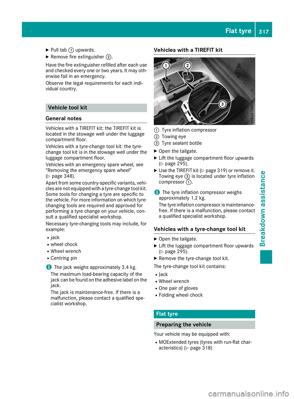
X
Pull tab :upwards.
X Remove fire extinguisher ;.
Have the fire extinguisher refilled after each use and checked every one or two years. It may oth-
erwise fail in an emergency.
Observe the legal requirements for each indi-
vidual country. Vehicle tool kit
General notes Vehicles with a TIREFIT kit: the TIREFIT kit is
located in the stowage well under the luggage
compartment floor.
Vehicles with a tyre-change tool kit: the tyre-
change tool kit is in the stowage well under the
luggage compartment floor.
Vehicles with an emergency spare wheel, see
"Removing the emergency spare wheel"
(Y page 348).
Apart from some country-specific variants, vehi- cles are not equipped with a tyre-change tool kit.Some tools for changing a tyre are specific to
the vehicle. For more information on which tyre-
changing tools are required and approved for
performing a tyre change on your vehicle, con-
sult a qualified specialist workshop.
Necessary tyre-changing tools may include, for
example:
R jack
R wheel chock
R Wheel wrench
R Centring pin
i The jack weighs approximately 3.4 kg.
The maximum load-bearing capacity of the
jack can be found on the adhesive label on the jack.
The jack is maintenance-free. If there is a
malfunction, please contact a qualified spe-
cialist workshop. Vehicles with a TIREFIT kit :
Tyre inflation compressor
; Towing eye
= Tyre sealant bottle
X Open the tailgate.
X Lift the luggage compartment floor upwards
(Y page 295).
X Use the TIREFIT kit (Y page 319) or remove it.
Towing eye =is located under tyre inflation
compressor :.
i The tyre inflation compressor weighs
approximately 1.2 kg.
The tyre inflation compressor is maintenance-
free. If there is a malfunction, please contact a qualified specialist workshop.
Vehicles with a tyre-change tool kit X
Open the tailgate.
X Lift the luggage compartment floor upwards
(Y page 295).
X Remove the tyre-change tool kit.
The tyre-change tool kit contains:
R Jack
R Wheel wrench
R One pair of gloves
R Folding wheel chock Flat tyre
Preparing the vehicle
Your vehicle may be equipped with: R MOExtended tyres (tyres with run-flat char-
acteristics) (Y page 318) Flat tyre
317Breakdown assistance
Page 321 of 369
Vehicle preparation is not necessary on vehi-
cles with MOExtended tyres.
R a TIREFIT kit (Y page 317)
R an emergency spare wheel (certain countries
only) (Y page 348)
Vehicles with MOExtended tyres are not equip-
ped with a TIREFIT kit at the factory. It is there-
fore recommended that you additionally equip
your vehicle with a TIREFIT kit if you fit tyres that do not feature run-flat characteristics, e.g. win-
ter tyres. A TIREFIT kit can be obtained from a
qualified specialist workshop.
Information on changing and fitting a wheel
(Y page 342).
X Stop the vehicle as far away as possible from
traffic on solid, non-slippery and level ground.
X Switch on the hazard warning lamps.
X Secure the vehicle against rolling away
(Y page 166).
X If possible, bring the front wheels into the
straight-ahead position.
X Switch off the engine.
X Vehicles without KEYLESS-GO: remove the
key from the ignition lock.
X Vehicles with KEYLESS-GO start-function
or KEYLESS-GO: open the driver's door.
The vehicle electronics are now in position
g. This is the same as “key removed”.
X Vehicles with KEYLESS-GO start function
or KEYLESS-GO: remove the Start/Stop but-
ton from the ignition lock (Y page 144).
X Make sure that the passengers are not endan-
gered as they get out of the vehicle. Make
sure that no one is near the danger area while
a wheel is being changed. Anyone who is not directly assisting in the wheel change should, for example, stand behind the barrier.
X Get out of the vehicle. Pay attention to traffic
conditions when doing so.
X Close the driver's door.
X Place the warning triangle a suitable distance
away (Y page 316). Observe legal require-
ments. MOExtended tyres (tyres with run-flat
characteristics)
General notes With MOExtended tyres (tyres with run-flat char-
acteristics), you can continue to drive your vehi- cle even if there is a total loss of pressure in one
or more tyres. The affected tyre must not show
any clearly visible damage.
You can recognise MOExtended tyres by the
"MOExtended" mark that appears on the tyre
sidewall. You will find this mark next to the tyre
size designation, the load-bearing capacity and
the speed index.
MOExtended tyres may be used only in conjunc- tion with an activated tyre pressure loss warning
system or tyre pressure monitor.
If a pressure loss warning message appears in the multifunction display:
R observe the instructions in the display mes-
sages (Y page 256)
R check the tyre for damage
R if driving on, observe the following notes
The driving distance possible in run-flat mode is approximately 80 km when the vehicle is parti-
ally laden and approximately 30 km when the
vehicle is fully laden.
In addition to the vehicle load, the driving dis-
tance possible in run-flat mode depends on the:
R vehicle speed
R road condition
R outside temperature
The driving distance possible in run-flat mode
may be reduced by extreme driving conditions/ manoeuvres, or it can be increased through a
moderate style of driving.
The driving distance possible in run-flat mode iscounted from the moment the tyre pressure loss
warning appears on the multifunction display.
You must not exceed a maximum speed of
80 km/h.
When replacing one or all tyres, observe the fol-
lowing specifications for your vehicle's tyres:
R size
R type and
R the "MOExtended" marking
If a tyre has gone flat and cannot be replaced
with an MOExtended tyre, a standard tyre may
be used as a temporary measure. Make sure 318
Flat tyreBreakdown assistance
Page 347 of 369
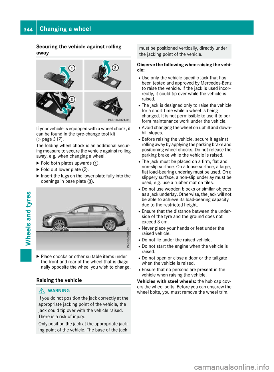
Securing the vehicle against rolling
away
If your vehicle is equipped with a wheel chock, it
can be found in the tyre-change tool kit
(Y page 317).
The folding wheel chock is an additional secur-
ing measure to secure the vehicle against rolling away, e.g. when changing a wheel.
X Fold both plates upwards :.
X Fold out lower plate ;.
X Insert the lugs on the lower plate fully into the
openings in base plate =.X
Place chocks or other suitable items under
the front and rear of the wheel that is diago-
nally opposite the wheel you wish to change.
Raising the vehicle G
WARNING
If you do not position the jack correctly at the appropriate jacking point of the vehicle, the
jack could tip over with the vehicle raised.
There is a risk of injury.
Only position the jack at the appropriate jack-
ing point of the vehicle. The base of the jack must be positioned vertically, directly under
the jacking point of the vehicle.
Observe the following when raising the vehi- cle:
R Use only the vehicle-specific jack that has
been tested and approved by Mercedes-Benz
to raise the vehicle. If the jack is used incor-
rectly, it could tip over while the vehicle is
raised.
R The jack is designed only to raise the vehicle
for a short time while a wheel is being
changed. It is not permissible to use it to per-
form maintenance work under the vehicle.
R Avoid changing the wheel on uphill and down-
hill slopes.
R Before raising the vehicle, secure it against
rolling away by applying the parking brake and
positioning wheel chocks. Do not release the parking brake while the vehicle is raised.
R The jack must be placed on a firm, flat and
non-slip surface. On a loose surface, a large,
flat load-bearing underlay must be used. On a
slippery surface, a non-slip underlay must be
used, e.g. use a rubber mat on tiles.
R Do not use wooden blocks or similar objects
as a jack underlay. Otherwise, the jack will not be able to achieve its load-bearing capacity
due to the restricted height.
R Ensure that the distance between the under-
side of the tyre and the ground does not
exceed 3 cm.
R Never place your hands or feet under the
raised vehicle.
R Do not lie under the raised vehicle.
R Do not start the engine when the vehicle is
raised.
R Do not open or close a door or the tailgate
when the vehicle is raised.
R Ensure that no persons are present in the
vehicle when raising the vehicle.
Vehicles with steel wheels: the hub cap cov-
ers the wheel bolts. Before you can unscrew the wheel bolts, you must remove the wheel trim. 344
Changing a wheelWheels and tyres