Page 257 of 372

arm with the other hand (move the wiper
blade toward the right side of the vehicle
to separate the wiper blade from the wiper
arm).
4. Gently lower the wiper arm onto the glass. Installing The Front Wipers
1. Lift the wiper arm off of the glass, until
the wiper arm is in the full up position.
2. Position the wiper blade near the hook on the tip of the wiper arm with the wiper
release tab open and the blade side of the
wiper facing up and away from the
windshield.
3. Insert the hook on the tip of the arm through the opening in the wiper blade
under the release tab.
4. Slide the wiper blade up into the hook on the wiper arm and rotate the wiper blade
until it is flush against the wiper arm. Fold
down the latch release tab and snap it into
its locked position. Latch engagement will
be accompanied by an audible click.
5. Gently lower the wiper blade onto the glass.
Rear Wiper Blade Removal/Installation
1. Lift the rear wiper arm pivot cap awayfrom the glass to allow the rear wiper
blade to be raised off of the glass. NOTE:
The rear wiper arm cannot be fully raised
off the glass unless the wiper arm pivot
cap is unsnapped first. Attempting to fully
raise the rear wiper arm without unsnap-
ping the wiper arm pivot cap may damage
the vehicle.
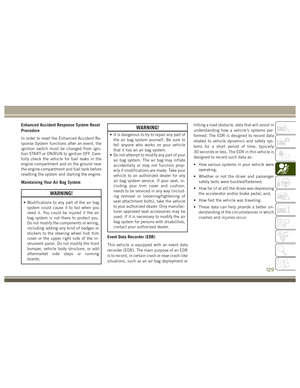
Wiper Blade Removed From Wiper Arm
1 — Wiper Blade
2 — Release Tab
3 — Wiper Arm
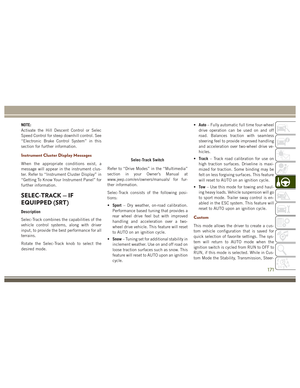
Wiper Pivot Cap In Unlocked Position
1 — Wiper Arm Pivot Cap
2 — Wiper Arm
3 — Wiper Blade
255
Page 258 of 372
2. Lift the rear wiper arm fully off the glass. 3. To remove the wiper blade from the wiperarm, grasp the bottom end of the wiper
blade nearest to wiper arm with your right
hand. With your left hand hold the wiper
arm as you pull the wiper blade away from
the wiper arm past its stop far enough to
unsnap the wiper blade pivot pin from the
receptacle on the end of the wiper arm.
NOTE:
Resistance will be accompanied by an
audible snap.
4. Still grasping the bottom end of the wiper blade, move the wiper blade upward and
away from the wiper arm to disengage.
5. Gently lower the tip of the wiper arm ontothe glass.
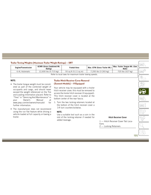
Wiper Blade In Folded Out Position
1 — Wiper Arm Pivot Cap
2 — Wiper Arm
3 — Wiper Blade
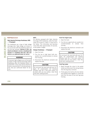
Wiper Blade Removed From Wiper Arm
1 — Wiper Arm
2 — Wiper BladeSERVICING AND MAINTENANCE
256
Page 259 of 372

Installing The Rear Wiper
1. Lift the rear wiper arm pivot cap awayfrom the glass to allow the rear wiper
blade to be raised off of the glass.
NOTE:
The rear wiper arm cannot be fully raised
off the glass unless the wiper arm pivot
cap is unsnapped first. Attempting to fully
raise the rear wiper arm without unsnap-
ping the wiper arm pivot cap may damage
the vehicle.
2. Lift the rear wiper arm fully off the glass.
3. Insert the wiper blade pivot pin into the opening on the end of the wiper arm. Grab
the bottom end of the wiper arm with one
hand, and press the wiper blade flush with
the wiper arm until it snaps into place.
4. Lower the wiper blade onto the glass and snap the wiper arm pivot cap back into
place.Cooling System
WARNING!
You or others can be badly burned by hot
engine coolant (antifreeze) or steam from
your radiator. If you see or hear steam
coming from under the hood, do not open
the hood until the radiator has had time to
cool. Never try to open a cooling system
pressure cap when the radiator or coolant
bottle is hot.
Engine Coolant Checks
Check the engine coolant (antifreeze) protec-
tion every 12 months (before the onset of
freezing weather, where applicable). If the
engine coolant (antifreeze) is dirty, the sys-
tem should be drained, flushed, and refilled
with fresh OAT coolant (conforming to
MS.90032) by an authorized dealer. Check the front of the A/C condenser for any accu-
mulation of bugs, leaves, etc. If dirty, clean
by gently spraying water from a garden hose
vertically down the face of the condenser.
Check the engine cooling system hoses for
brittle rubber, cracking, tears, cuts, and
tightness of the connection at the coolant
recovery bottle and radiator. Inspect the en-
tire system for leaks.
With the engine at normal operating tempera-
ture (but not running), check the cooling
system pressure cap for proper vacuum seal-
ing by draining a small amount of engine
coolant (antifreeze) from the radiator drain
cock. If the cap is sealing properly, the engine
coolant (antifreeze) will begin to drain from
the coolant recovery bottle. DO NOT RE-
MOVE THE COOLANT PRESSURE CAP
WHEN THE COOLING SYSTEM IS HOT.
257
Page 260 of 372

RAISING THE VEHICLE
In the case where it is necessary to raise the
vehicle, go to an authorized dealer or service
station.
TIRES
Tire Safety Information
Tire safety information will cover aspects of
the following information: Tire Markings, Tire
Identification Numbers, Tire Terminology and
Definitions, Tire Pressures and Tire Loading.
Tire Markings
NOTE:
• P (Passenger) — Metric tire sizing isbased on U.S. design standards. P-Metric
tires have the letter “P” molded into the
sidewall preceding the size designation.
Example: P215/65R15 95H. • European — Metric tire sizing is based on
European design standards. Tires de-
signed to this standard have the tire size
molded into the sidewall beginning with
the section width. The letter "P" is absent
from this tire size designation. Example:
215/65R15 96H.
• LT (Light Truck) — Metric tire sizing is based on U.S. design standards. The size
designation for LT-Metric tires is the same
as for P-Metric tires except for the letters
“LT” that are molded into the sidewall
preceding the size designation. Example:
LT235/85R16.
• Temporary spare tires are designed for temporary emergency use only. Temporary
high pressure compact spare tires have
the letter “T” or “S” molded into the
sidewall preceding the size designation.
Example: T145/80D18 103M.
• High flotation tire sizing is based on U.S. design standards and it begins with the
tire diameter molded into the sidewall.
Example: 31x10.5 R15 LT.
1 — U.S. DOT
Safety Standards
Code (TIN) 4 — Maximum
Load
2 — Size Designa-
tion 5 — Maximum
Pressure
3 — Service De-
scription 6 — Treadwear,
Traction and Tem-
perature Grades
SERVICING AND MAINTENANCE
258
Page 261 of 372

Tire Identification Number (TIN)
The TIN may be found on one or both sides of
the tire, however, the date code may only be
on one side. Tires with white sidewalls will
have the full TIN, including the date code,located on the white sidewall side of the tire.
Look for the TIN on the outboard side of black
sidewall tires as mounted on the vehicle. If
the TIN is not found on the outboard side,
then you will find it on the inboard side of the
tire.
EXAMPLE:
DOT MA L9 ABCD 0301
DOT = Department of Transportation
– This symbol certifies that the tire is in compliance with the U.S. Department of Transportation tire safety standards and is ap-
proved for highway use
MA = Code representing the tire manufacturing location (two digits)
L9 = Code representing the tire size (two digits)
ABCD = Code used by the tire manufacturer (one to four digits)
03 = Number representing the week in which the tire was manufactured (two digits)
– 03 means the 3rd week
01 = Number representing the year in which the tire was manufactured (two digits)
– 01 means the year 2001
– Prior to July 2000, tire manufacturers were only required to have one number to represent the year in which the tire was manufac-
tured. Example: 031 could represent the 3rd week of 1981 or 1991
259
Page 262 of 372

Tire Terminology And Definitions
TermDefinition
B-Pillar The vehicle B-Pillar is the structural member of the body located behind the front
door.
Cold Tire Inflation Pressure Cold tire inflation pressure is defined as the tire pressure after the vehicle has not
been driven for at least three hours, or driven less than 1 mile (1.6 km) after sitting
for a minimum of three hours. Inflation pressure is measured in units of PSI (pounds
per square inch) or kPa (kilopascals).
Maximum Inflation Pressure The maximum inflation pressure is the maximum permissible cold tire inflation pres-
sure for this tire. The maximum inflation pressure is molded into the sidewall.
Recommended Cold Tire Inflation Pressure Vehicle manufacturer's recommended cold tire inflation pressure as shown on the tire
placard.
Tire Placard A label permanently attached to the vehicle describing the vehicle’s loading capacity,
the original equipment tire sizes and the recommended cold tire inflation pressures.
SERVICING AND MAINTENANCE
260
Page 263 of 372
Tire Loading And Tire Pressure
NOTE:
The proper cold tire inflation pressure is
listed on the driver’s side B-Pillar or the rear
edge of the driver's side door.Tire And Loading Information PlacardThis placard tells you important information
about the:
• Number of people that can be carried in
the vehicle.
• Total weight your vehicle can carry.
• Tire size designed for your vehicle.
• Cold tire inflation pressures for the front, rear, and spare tires.
Loading
The vehicle maximum load on the tire must
not exceed the load carrying capacity of the
tire on your vehicle. You will not exceed the
tire's load carrying capacity if you adhere to
the loading conditions, tire size, and cold tire
inflation pressures specified on the Tire and
Loading Information placard in “Vehicle
Loading” in the “Starting And Operating”
section of this manual.
Example Tire Placard Location (Door)
Example Tire Placard Location (B-Pillar)
Tire And Loading Information Placard
261
Page 264 of 372

NOTE:
Under a maximum loaded vehicle condition,
gross axle weight ratings (GAWRs) for the
front and rear axles must not be exceeded.
For further information on GAWRs, vehicle
loading, and trailer towing, refer to “Vehicle
Loading” in the “Starting And Operating”
section of this manual.
To determine the maximum loading condi-
tions of your vehicle, locate the statement
“The combined weight of occupants and
cargo should never exceed XXX kg or XXX lbs”
on the Tire and Loading Information placard.
The combined weight of occupants, cargo/
luggage and trailer tongue weight (if appli-
cable) should never exceed the weight refer-
enced here.
Steps For Determining Correct Load
Limit—
(1) Locate the statement “The com-
bined weight of occupants and cargo
should never exceed XXX kg or
XXX lbs.” on your vehicle's placard.(2) Determine the combined weight of
the driver and passengers that will be
riding in your vehicle.
(3) Subtract the combined weight of
the driver and passengers from XXX kg
or XXX lbs.
(4) The resulting figure equals the
available amount of cargo and luggage
load capacity. For example, if “XXX”
amount equals 1400 lbs. and there
will be five 150 lb passengers in your
vehicle, the amount of available cargo
and luggage load capacity is 650 lbs.
(1400-750 (5x150) = 650 lbs.)
(5)Determine the combined weight of
luggage and cargo being loaded on the
vehicle. That weight may not safely ex-
ceed the available cargo and luggage
load capacity calculated in Step 4.
(6) If your vehicle will be towing a
trailer, load from your trailer will be
transferred to your vehicle. Consult this manual to determine how this
reduces the available cargo and lug-
gage load capacity of your vehicle.
Metric Example For Load Limit
For example, if “XXX” amount equals 635 kg
and there will be five 68 kg passengers in
your vehicle, the amount of available cargo
and luggage load capacity is 295 kg (635-
340 (5x68) = 295 kg) as shown in step 4.
NOTE:
• If your vehicle will be towing a trailer, load
from your trailer will be transferred to your
vehicle. The following table shows ex-
amples on how to calculate total load,
cargo/luggage, and towing capacities of
your vehicle with varying seating configu-
rations and number and size of occupants.
This table is for illustration purposes only
and may not be accurate for the seating
and load carry capacity of your vehicle.
• For the following example, the combined weight of occupants and cargo should
never exceed 865 lbs (392 kg).
SERVICING AND MAINTENANCE
262