2016 NISSAN NOTE ESP
[x] Cancel search: ESPPage 1380 of 3641
![NISSAN NOTE 2016 Service Repair Manual P0172 FUEL INJECTION SYSTEM FUNCTIONEC-253
< DTC/CIRCUIT DIAGNOSIS > [HR16DE]
C
D
E
F
G H
I
J
K L
M A
EC
NP
O
1. Turn ignition switch OFF and wait at least 10 seconds.
2. Start engine.
3. Maintain the NISSAN NOTE 2016 Service Repair Manual P0172 FUEL INJECTION SYSTEM FUNCTIONEC-253
< DTC/CIRCUIT DIAGNOSIS > [HR16DE]
C
D
E
F
G H
I
J
K L
M A
EC
NP
O
1. Turn ignition switch OFF and wait at least 10 seconds.
2. Start engine.
3. Maintain the](/manual-img/5/57363/w960_57363-1379.png)
P0172 FUEL INJECTION SYSTEM FUNCTIONEC-253
< DTC/CIRCUIT DIAGNOSIS > [HR16DE]
C
D
E
F
G H
I
J
K L
M A
EC
NP
O
1. Turn ignition switch OFF and wait at least 10 seconds.
2. Start engine.
3. Maintain the following conditions for at least 10 consecutive minutes.
Hold the accelerator pedal as steady as possible.
CAUTION:
Always drive vehicle at a safe speed.
4. Check 1st trip DTC.
Is 1st trip DTC detected?
YES >> Go to EC-253, "Diagnosis Procedure".
NO >> INSPECTION END
Diagnosis ProcedureINFOID:0000000012431458
1.CHECK EXHAUST GAS LEAK
1. Start engine and run it at idle.
2. Listen for an exhaust gas leak before three way catalyst (manifold).
Is exhaust gas leak detected?
YES >> Repair or replace.
NO >> GO TO 2.
2.CHECK FOR INTAKE AIR LEAK
Listen for an intake air leak after the mass air flow sensor.
Is intake air leak detected?
YES >> Repair or replace.
NO >> GO TO 3.
3.CHECK A/F SENSOR 1 INPUT SIGNAL CIRCUIT FOR OPEN AND SHORT
1. Turn ignition switch OFF.
2. Disconnect corresponding A/F sensor 1 harness connector.
3. Disconnect ECM harness connector.
4. Check the continuity between A/F sensor 1 harness connector and ECM harness connector.
5. Check the continuity between A/F sensor 1 harness connector or ECM harness connector and ground.
VHCL SPEED SE50 – 120 km/h (31 – 75 MPH)
PBIB1216E
A/F sensor 1ECM
Continuity
Connector Terminal Connector Terminal
F12 1
F11 49
Existed
25 3
A/F sensor 1 GroundContinuity
Connector Terminal
F12 1
Ground Not existed
2
Revision: August 2015 2016 Versa Note
cardiagn.com
Page 1491 of 3641
![NISSAN NOTE 2016 Service Repair Manual EC-364
< DTC/CIRCUIT DIAGNOSIS >[HR16DE]
P1148 CLOSED LOOP CONTROL
P1148 CLOSED LOOP CONTROL
DTC LogicINFOID:0000000012431563
DTC DETECTION LOGIC
NOTE:
DTC P1148 is displayed with DTC for A/F sensor 1 NISSAN NOTE 2016 Service Repair Manual EC-364
< DTC/CIRCUIT DIAGNOSIS >[HR16DE]
P1148 CLOSED LOOP CONTROL
P1148 CLOSED LOOP CONTROL
DTC LogicINFOID:0000000012431563
DTC DETECTION LOGIC
NOTE:
DTC P1148 is displayed with DTC for A/F sensor 1](/manual-img/5/57363/w960_57363-1490.png)
EC-364
< DTC/CIRCUIT DIAGNOSIS >[HR16DE]
P1148 CLOSED LOOP CONTROL
P1148 CLOSED LOOP CONTROL
DTC LogicINFOID:0000000012431563
DTC DETECTION LOGIC
NOTE:
DTC P1148 is displayed with DTC for A/F sensor 1.
When the DTC is detected, perform the trouble di
agnosis of DTC corresponding to A/F sensor 1.
Diagnosis ProcedureINFOID:0000000012431564
DTC P1148 is displayed with DTC for A/F sensor 1.
When the DTC is detected, perform the trouble diagnosis of DTC corresponding to A/F sensor 1.
Refer to EC-87, "
DTCIndex".
DTC No. CONSULT screen terms
(Trouble diagnosis content) DTC detecting condition
Possible cause
P1148 CLOSED LOOP-B1
(Closed loop control func-
tion) The closed loop control function does not
operate even when vehicle is being driven in
the specified condition. • Harness or connectors
(A/F sensor 1 circuit is open or shorted.)
• A/F sensor 1
• A/F sensor 1 heater
Revision: August 2015 2016 Versa Note
cardiagn.com
Page 1662 of 3641
EXL-10
< SYSTEM DESCRIPTION >
SYSTEM
FRONT FOG LAMP SYSTEM : System Description
INFOID:0000000012432774
FRONT FOG LAMP OPERATION
When the combination switch (lighting and turn signal switch) is in front fog lamp ON position and also in 1ST
or 2ND position (headlamp is ON), the BCM detects FR FOG ON and the HEAD LAMP 1 or 2 ON. The BCM
sends a front fog lamp request ON signal through the CAN communication lines to the IPDM E/R. The IPDM
E/R then turns ON the front fog lamp relay sending power to the front fog lamps.
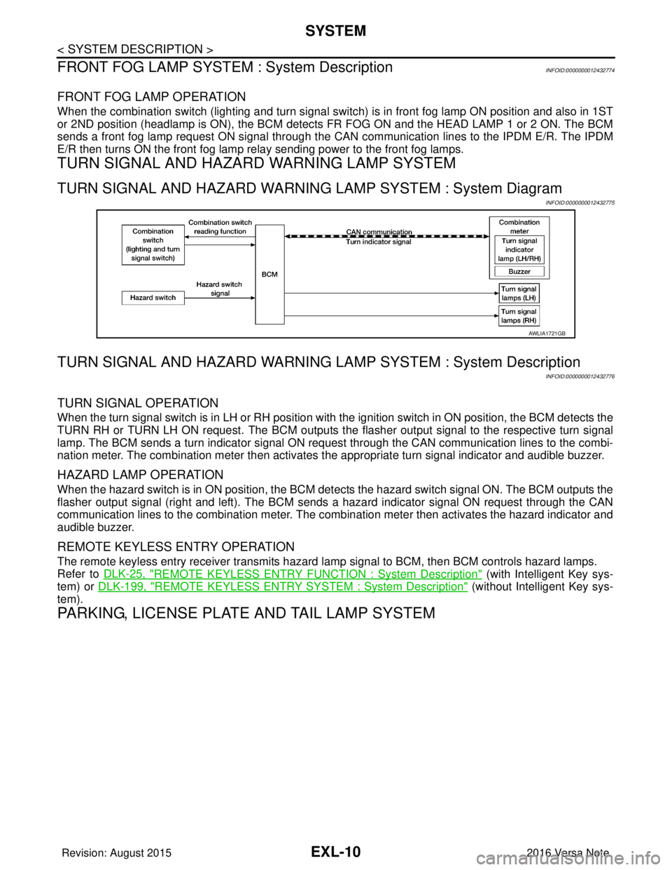
TURN SIGNAL AND HAZARD WARNING LAMP SYSTEM
TURN SIGNAL AND HAZARD WARNING LAMP SYSTEM : System Diagram
INFOID:0000000012432775
TURN SIGNAL AND HAZARD WARNING LA MP SYSTEM : System Description
INFOID:0000000012432776
TURN SIGNAL OPERATION
When the turn signal switch is in LH or RH position with the ignition switch in ON position, the BCM detects the
TURN RH or TURN LH ON request. The BCM outputs the flasher output signal to the respective turn signal
lamp. The BCM sends a turn indicator signal ON request through the CAN communication lines to the combi-
nation meter. The combination meter then activates the appropriate turn signal indicator and audible buzzer.
HAZARD LAMP OPERATION
When the hazard switch is in ON position, the BCM det ects the hazard switch signal ON. The BCM outputs the
flasher output signal (right and left). The BCM sends a hazard indicator signal ON request through the CAN
communication lines to the combination meter. The combination meter then activates the hazard indicator and
audible buzzer.
REMOTE KEYLESS ENTRY OPERATION
The remote keyless entry receiver transmits hazard lamp signal to BCM, then BCM controls hazard lamps.
Refer to DLK-25, "
REMOTE KEYLESS ENTRY FUNCTION : System Description" (with Intelligent Key sys-
tem) or DLK-199, "
REMOTE KEYLESS ENTRY SYSTEM : System Description" (without Intelligent Key sys-
tem).
PARKING, LICENSE PLATE AND TAIL LAMP SYSTEM
AWLIA1721GB
Revision: August 2015 2016 Versa Note
cardiagn.com
Page 1778 of 3641
SYSTEMEXT-11
< SYSTEM DESCRIPTION >
C
DE
F
G H
I
J
L
M A
B
EXT
N
O P
SYSTEM
ACTIVE GRILLE SHUTTER SYSTEM
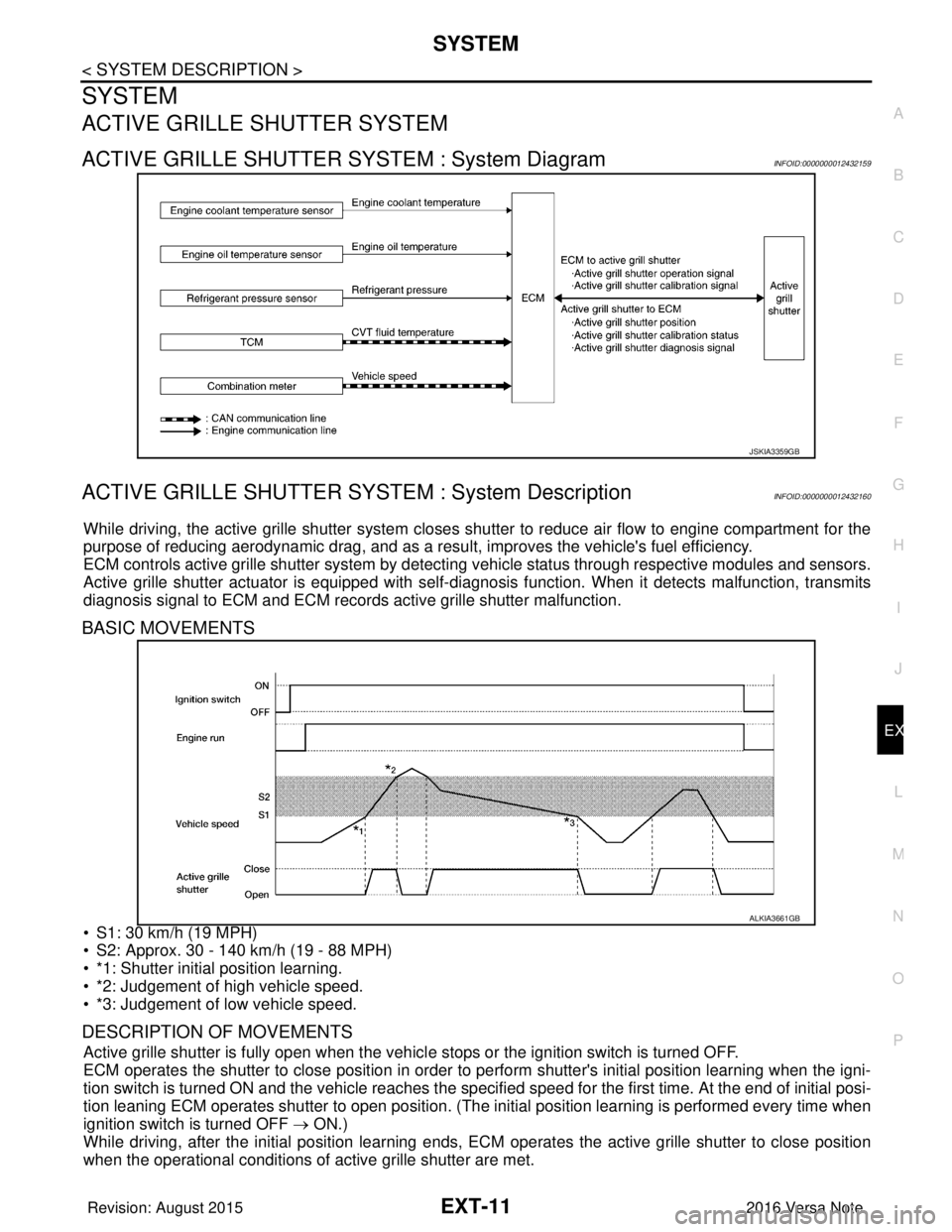
ACTIVE GRILLE SHUTTER SYSTEM : System DiagramINFOID:0000000012432159
ACTIVE GRILLE SHUTTER SYSTEM : System DescriptionINFOID:0000000012432160
While driving, the active grille shutter system closes shutter to reduce air flow to engine compartment for the
purpose of reducing aerodynamic drag, and as a resu lt, improves the vehicle's fuel efficiency.
ECM controls active grille shutter system by detecting vehicle status through respective modules and sensors.
Active grille shutter actuator is equipped with self-d iagnosis function. When it detects malfunction, transmits
diagnosis signal to ECM and ECM records active grille shutter malfunction.
BASIC MOVEMENTS
• S1: 30 km/h (19 MPH)
• S2: Approx. 30 - 140 km/h (19 - 88 MPH)
• *1: Shutter initial position learning.
• *2: Judgement of high vehicle speed.
• *3: Judgement of low vehicle speed.
DESCRIPTION OF MOVEMENTS
Active grille shutter is fully open when the vehicl e stops or the ignition switch is turned OFF.
ECM operates the shutter to close position in order to perform shutter's initial position learning when the igni-
tion switch is turned ON and the vehicle reaches the specified speed for the first time. At the end of initial posi-
tion leaning ECM operates shutter to open position. (The in itial position learning is performed every time when
ignition switch is turned OFF → ON.)
While driving, after the initial position learning ends, EC M operates the active grille shutter to close position
when the operational conditions of active grille shutter are met.
JSKIA3359GB
ALKIA3661GB
Revision: August 2015 2016 Versa Note
cardiagn.com
Page 1784 of 3641
SQUEAK AND RATTLE TROUBLE DIAGNOSESEXT-17
< SYMPTOM DIAGNOSIS >
C
DE
F
G H
I
J
L
M A
B
EXT
N
O P
SYMPTOM DIAGNOSIS
SQUEAK AND RATTLE TROUBLE DIAGNOSES
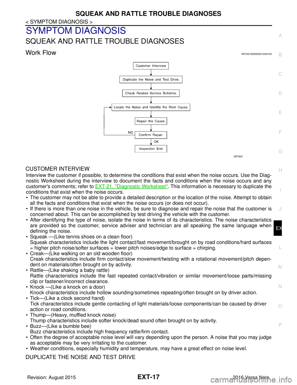
Work FlowINFOID:0000000012432162
CUSTOMER INTERVIEW
Interview the customer if possible, to determine the conditions that exist when the noise occurs. Use the Diag-
nostic Worksheet during the interv iew to document the facts and conditions when the noise occurs and any
customer's comments; refer to EXT-21, "
Diagnostic Worksheet". This information is necessary to duplicate the
conditions that exist when the noise occurs.
• The customer may not be able to provide a detailed descr iption or the location of the noise. Attempt to obtain
all the facts and conditions that exist when the noise occurs (or does not occur).
• If there is more than one noise in the vehicle, be sure to diagnose and repair the noise that the customer is
concerned about. This can be accomplished by test driving the vehicle with the customer.
• After identifying the type of noise, isolate the noise in terms of its characteristics. The noise characteristics are provided so the customer, service adviser and technician are all speaking the same language when
defining the noise.
• Squeak —(Like tennis shoes on a clean floor) Squeak characteristics include the light contact/fast movement/brought on by road conditions/hard surfaces
= higher pitch noise/softer surfaces = lower pitch noises/edge to surface = chirping.
• Creak—(Like walking on an old wooden floor) Creak characteristics include firm contact/slow mo vement/twisting with a rotational movement/pitch depen-
dent on materials/often brought on by activity.
• Rattle—(Like shaking a baby rattle) Rattle characteristics include the fast repeated contac t/vibration or similar movement/loose parts/missing
clip or fastener/incorrect clearance.
• Knock —(Like a knock on a door) Knock characteristics include hollow sounding/someti mes repeating/often brought on by driver action.
• Tick—(Like a clock second hand) Tick characteristics include gentle contacting of li ght materials/loose components/can be caused by driver
action or road conditions.
• Thump—(Heavy, muffled knock noise)
Thump characteristics include softer k nock/dead sound often brought on by activity.
• Buzz—(Like a bumble bee) Buzz characteristics include high frequency rattle/firm contact.
• Often the degree of acceptable noise level will vary depending upon the person. A noise that you may judge as acceptable may be very irritating to the customer.
• Weather conditions, especially humidity and temperature, may have a great effect on noise level.
DUPLICATE THE NOISE AND TEST DRIVE
SBT842
Revision: August 2015 2016 Versa Note
cardiagn.com
Page 1830 of 3641
FRONT WHEEL HUB AND KNUCKLEFAX-13
< REMOVAL AND INSTALLATION >
CEF
G H
I
J
K L
M A
B
FA X
N
O P
5. Perform inspection after assembly. Refer to FAX-13, "Inspection".
InspectionINFOID:0000000012431893
INSPECTION AFTER REMOVAL
Check the following items, and replace the part if necessary.
• Check components for deformation, cracks, and other damage.
• Check boots of transverse link and steering outer so cket ball joint for breakage, axial end play, and swing
torque. Refer to FSU-10, "
Inspection" and FSU-20, "Ball Joint".
INSPECTION AFTER DISASSEMBLY
Wheel Hub
• Check wheel hub for cracks (with magnetic exploration or dye testing). Replace if necessary.
Steering Knuckle
• Check steering knuckle for deformation, cracks, and other damage. Replace if any non-standard conditions
are found.
Snap Rings
• Check snap ring for wear or cracks. Replace if necessary.
INSPECTION AFTER ASSEMBLY
Check wheel bearing rotating torque as per the following instructions.
NOTE:
The adequacy of turning torque can be judged from a measurement value by a spring balancer.
1. For a proper fit of the bearing, turn the wheel hub clockwise and counterclockwise, respectively, 10 times
or more with a press-fit load applied.
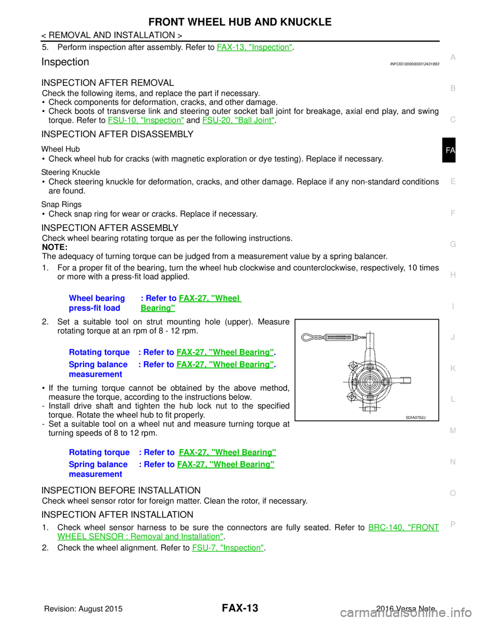
2. Set a suitable tool on strut mounting hole (upper). Measure rotating torque at an rpm of 8 - 12 rpm.
• If the turning torque cannot be obtained by the above method, measure the torque, according to the instructions below.
- Install drive shaft and tighten the hub lock nut to the specified
torque. Rotate the wheel hub to fit properly.
- Set a suitable tool on a wheel nut and measure turning torque at turning speeds of 8 to 12 rpm.
INSPECTION BEFORE INSTALLATION
Check wheel sensor rotor for foreign matter. Clean the rotor, if necessary.
INSPECTION AFTER INSTALLATION
1. Check wheel sensor harness to be sure the connectors are fully seated. Refer to BRC-140, "FRONT
WHEEL SENSOR : Removal and Installation".
2. Check the wheel alignment. Refer to FSU-7, "
Inspection".
Wheel bearing
press-fit load
: Refer to
FAX-27, "
Wheel
Bearing"
Rotating torque : Refer to FAX-27, "Wheel Bearing".
Spring balance
measurement : Refer to
FAX-27, "
Wheel Bearing".
Rotating torque : Refer to FAX-27, "
Wheel Bearing"
Spring balance
measurement: Refer to
FAX-27, "Wheel Bearing"
SDIA0762J
Revision: August 2015 2016 Versa Note
cardiagn.com
Page 1871 of 3641
FUEL SYSTEMFL-5
< PERIODIC MAINTENANCE >
C
DE
F
G H
I
J
K L
M A
FL
NP
O
PERIODIC MAINTENANCE
FUEL SYSTEM
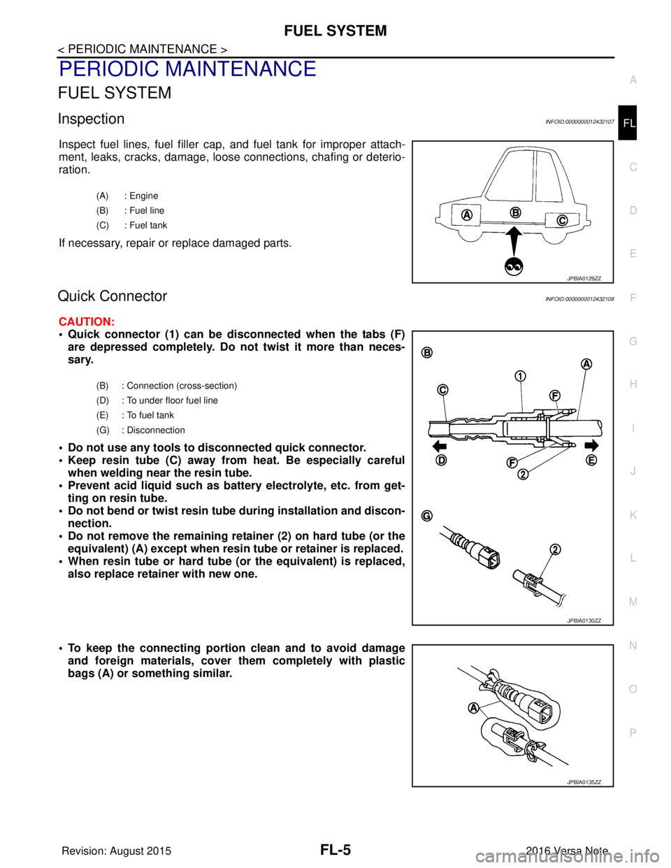
InspectionINFOID:0000000012432107
Inspect fuel lines, fuel filler cap,
and fuel tank for improper attach-
ment, leaks, cracks, damage, loos e connections, chafing or deterio-
ration.
If necessary, repair or replace damaged parts.
Quick ConnectorINFOID:0000000012432108
CAUTION:
• Quick connector (1) can be di sconnected when the tabs (F)
are depressed completely. Do not twist it more than neces-
sary.
• Do not use any tools to di sconnected quick connector.
• Keep resin tube (C) away from heat. Be especially careful when welding near the resin tube.
• Prevent acid liquid such as battery electrolyte, etc. from get- ting on resin tube.
• Do not bend or twist resin tube during installation and discon-
nection.
• Do not remove the remaining retainer (2) on hard tube (or the equivalent) (A) except when resin tu be or retainer is replaced.
• When resin tube or hard tube (or the equivalent) is replaced, also replace retainer with new one.
• To keep the connecting portion clean and to avoid damage and foreign materials, cover them completely with plastic
bags (A) or something similar.
(A) : Engine
(B) : Fuel line
(C) : Fuel tank
JPBIA0129ZZ
(B) : Connection (cross-section)
(D) : To under floor fuel line
(E) : To fuel tank
(G) : Disconnection
JPBIA0130ZZ
JPBIA0135ZZ
Revision: August 2015 2016 Versa Note
cardiagn.com
Page 1873 of 3641

FUEL LEVEL SENSOR UNIT, FUEL FILTER AND FUEL PUMP ASSEMBLYFL-7
< REMOVAL AND INSTALLATION >
C
DE
F
G H
I
J
K L
M A
FL
NP
O
Remove the quick connector as follows:
• Hold the sides of the connector, push in tabs (B) and pull (A)
out the tube.
• If the connector and the tube are stuck together, push and pull several times until they start to move. Then disconnect them
by pulling.
CAUTION:
• Quick connector (1) can be disconnected when the tabs (F) are depressed completely. Do not twist it more than
necessary.
• Do not use any tools to disconnected quick connector.
• Keep resin tube (C) away from heat. Be especially careful when welding near the resin tube.
• Prevent acid liquid such as battery electrolyte, etc. from
getting on resin tube.
• Do not bend or twist resin tube during installation and dis- connection.
• Do not remove the remaining retainer (2) on hard tube (or
the equivalent) (A) except when resin tube or retainer is
replaced.
• When resin tube or hard tube (or the equivalent) is
replaced, also replace retainer with new one.
• To keep the connecting portio n clean and to avoid dam-
age and foreign materials, cover them completely with
plastic bags (A) or something similar.
JPBIA0134ZZ
(B) : Connection (cross-section)
(D) : To under floor fuel line
(E) : To fuel tank
(G) : Disconnection
JPBIA0130ZZ
JPBIA0135ZZ
Revision: August 2015 2016 Versa Note
cardiagn.com