2016 NISSAN NOTE wheel torque
[x] Cancel search: wheel torquePage 2351 of 3641
MA-36
< PERIODIC MAINTENANCE >
CHASSIS AND BODY MAINTENANCE
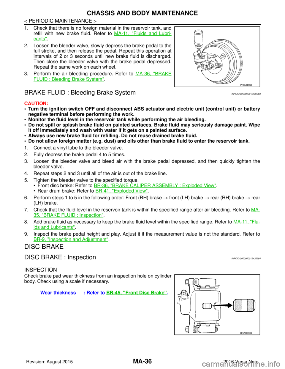
1. Check that there is no foreign material in the reservoir tank, andrefill with new brake fluid. Refer to MA-11, "
Fluids and Lubri-
cants".
2. Loosen the bleeder valve, slowly depress the brake pedal to the full stroke, and then release the pedal. Repeat this operation at
intervals of 2 or 3 seconds until new brake fluid is discharged.
Then close the bleeder valve with the brake pedal depressed.
Repeat the same work on each wheel.
3. Perform the air bleeding procedure. Refer to MA-36, "
BRAKE
FLUID : Bleeding Brake System".
BRAKE FLUID : Bleeding Brake SystemINFOID:0000000012432283
CAUTION:
• Turn the ignition switch OFF and disconnect ABS act uator and electric unit (control unit) or battery
negative terminal before performing the work.
• Monitor the fluid level in the reservoir tank while performing the air bleeding.
• Do not spill or splash brake fluid on painted su rfaces. Brake fluid may seriously damage paint. Wipe
it off immediately and wash with wa ter if it gets on a painted surface.
• Always use new brake fluid for refilling. Do not reuse drained brake fluid.
• Do not allow foreign matter (e.g. dust) and oils other than brake fluid to enter the reservoir tank.
1. Connect a vinyl tube to the bleeder valve.
2. Fully depress the brake pedal 4 to 5 times.
3. Loosen the bleeder valve and bleed air with the br ake pedal depressed, and then quickly tighten the
bleeder valve.
4. Repeat steps 2 and 3 until all of the air is out of the brake line.
5. Tighten the bleeder valve to the specified torque. • Front disc brake: Refer to BR-36, "
BRAKE CALIPER ASSEMBLY : Exploded View".
• Rear drum brake: Refer to BR-41, "
Exploded View".
6. Perform steps 1 to 5 in the following order: Front (RH) brake → front (LH) brake → rear (RH) brake → rear
(LH) brake.
7. Check that the fluid level in the reservoir tank is within the specified range after air bleeding. Refer to MA-
35, "BRAKE FLUID : Inspection".
8. Add brake fluid as necessary to keep the brake fluid level within the specified range. Refer to MA-11, "
Flu-
ids and Lubricants".
9. Inspect the brake pedal height and play. Adjust it if the measurement value is not the standard. Refer to
BR-9, "
Inspection and Adjustment".
DISC BRAKE
DISC BRAKE : InspectionINFOID:0000000012432284
INSPECTION
Check brake pad wear thickness from an inspection hole on cylinder
body. Check using a scale if necessary.
PFIA0403J
Wear thickness : Refer to BR-45, "Front Disc Brake".
BRA0010D
Revision: August 2015 2016 Versa Note
cardiagn.com
Page 2725 of 3641
REAR WHEEL HUBRAX-7
< REMOVAL AND INSTALLATION >
CEF
G H
I
J
K L
M A
B
RAX
N
O P
• Do not hammer the wheel stud a nd avoid impact to the brake drum.
• Press the wheel stud straight out to avoid damage.
7. Perform inspection after removal. Refer to RAX-9, "
Inspection".
INSTALLATION
Installation is in the reverse order of removal.
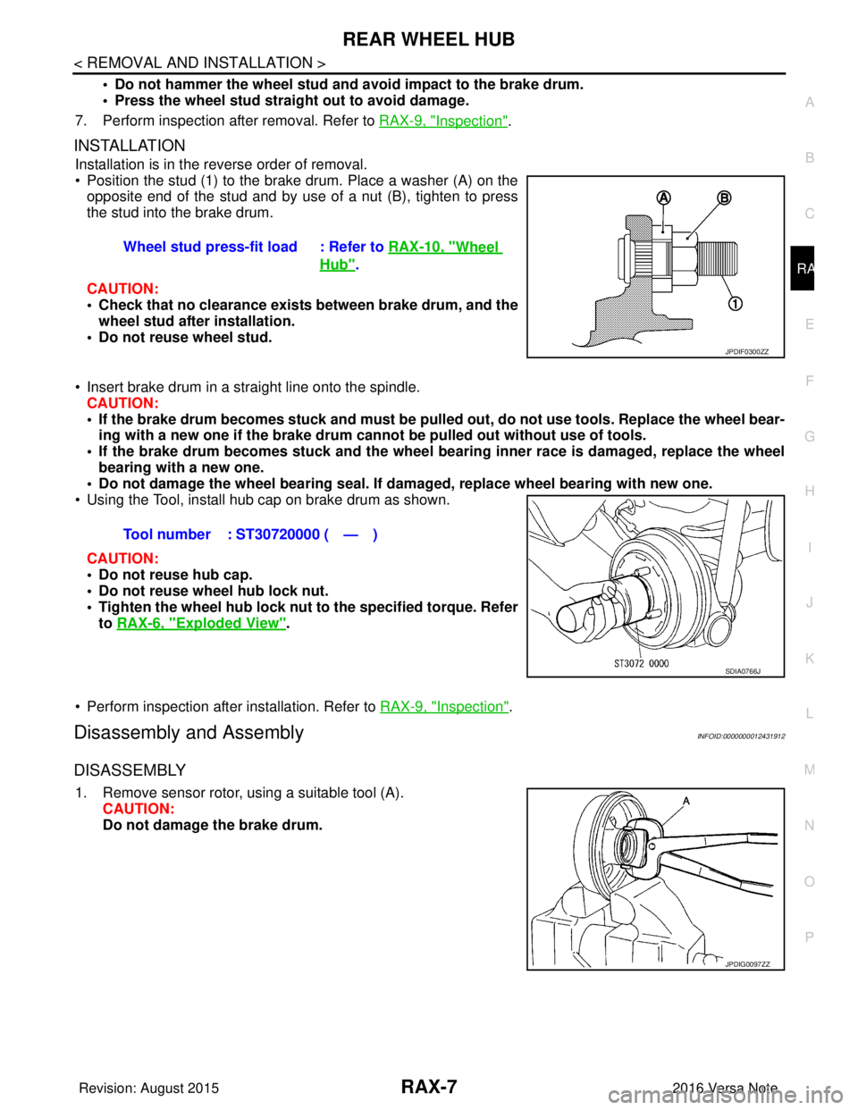
• Position the stud (1) to the brake drum. Place a washer (A) on the
opposite end of the stud and by use of a nut (B), tighten to press
the stud into the brake drum.
CAUTION:
• Check that no clearance exists between brake drum, and the wheel stud after installation.
• Do not reuse wheel stud.
• Insert brake drum in a straight line onto the spindle. CAUTION:
• If the brake drum becomes stuck and must be pulled out, do not use tools. Replace the wheel bear-
ing with a new one if the brake drum canno t be pulled out without use of tools.
• If the brake drum becomes stuck and the wheel bearing inner race is damaged, replace the wheel
bearing with a new one.
• Do not damage the wheel bearing seal. If da maged, replace wheel bearing with new one.
• Using the Tool, install hub cap on brake drum as shown.
CAUTION:
• Do not reuse hub cap.
• Do not reuse wheel hub lock nut.
• Tighten the wheel hub lock nut to the specified torque. Refer
to RAX-6, "
Exploded View".
• Perform inspection after installation. Refer to RAX-9, "
Inspection".
Disassembly and AssemblyINFOID:0000000012431912
DISASSEMBLY
1. Remove sensor rotor, using a suitable tool (A). CAUTION:
Do not damage the brake drum.Wheel stud press-fit load : Refer to
RAX-10, "
Wheel
Hub".
JPDIF0300ZZ
Tool number : ST30720000 ( — )
SDIA0766J
JPDIG0097ZZ
Revision: August 2015 2016 Versa Note
cardiagn.com
Page 2727 of 3641
REAR WHEEL HUBRAX-9
< REMOVAL AND INSTALLATION >
CEF
G H
I
J
K L
M A
B
RAX
N
O P
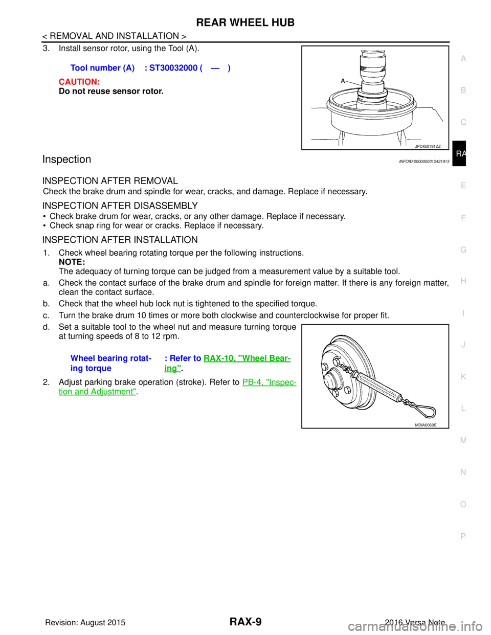
3. Install sensor rotor, using the Tool (A).
CAUTION:
Do not reuse sensor rotor.
InspectionINFOID:0000000012431913
INSPECTION AFTER REMOVAL
Check the brake drum and spindle for wear , cracks, and damage. Replace if necessary.
INSPECTION AFTER DISASSEMBLY
• Check brake drum for wear, cracks, or any other damage. Replace if necessary.
• Check snap ring for wear or cracks. Replace if necessary.
INSPECTION AFTER INSTALLATION
1. Check wheel bearing rotating torque per the following instructions. NOTE:
The adequacy of turning torque can be judged from a measurement value by a suitable tool.
a. Check the contact surface of the brake drum and spindle for foreign matter. If there is any foreign matter, clean the contact surface.
b. Check that the wheel hub lock nut is tightened to the specified torque.
c. Turn the brake drum 10 times or more bot h clockwise and counterclockwise for proper fit.
d. Set a suitable tool to the wheel nut and measure turning torque at turning speeds of 8 to 12 rpm.
2. Adjust parking brake operation (stroke). Refer to PB-4, "
Inspec-
tion and Adjustment".
Tool number (A) : ST30032000 ( — )
JPDIG0191ZZ
Wheel bearing rotat-
ing torque
: Refer to
RAX-10, "Wheel Bear-
ing".
MDIA0060E
Revision: August 2015 2016 Versa Note
cardiagn.com
Page 2728 of 3641

RAX-10
< SERVICE DATA AND SPECIFICATIONS (SDS)
SERVICE DATA AND SPECIFICATIONS (SDS)
SERVICE DATA AND SPECIFICATIONS (SDS)
SERVICE DATA AND SPECIFICATIONS (SDS)
Wheel BearingINFOID:0000000012431914
Wheel HubINFOID:0000000012431915
ItemStandard
Axial end play 0.0 mm (0.00 in) or less
Rotating torque 1.71 N·m (0.17 kg-m, 15 in-lb) or less
Spring balance measurement 34.2 N (3.49 kg, 7.69 lb) or less
Wheel bearing press-fit load 44.1 - 53.9 kN (4,498.2 - 5,497.8 kg-f, 9,913.7 - 12,116.7 lb-f)
ItemStandard
Wheel stud press-fit load 26.5 - 32.3 kN (2,703.0 - 3,294.6 kg-f, 5,957.2 - 7,261.0 lb-f)
Revision: August 2015 2016 Versa Note
cardiagn.com
Page 2789 of 3641
WT-46
< PERIODIC MAINTENANCE >
WHEEL AND TIRE
3. Install balance weight in the position shown.CAUTION:
• Do not install the inner bala nce weight before installing
the outer balance weight.
• Before installing the balance weight, be sure to clean the mating surface of the wheel and tire.
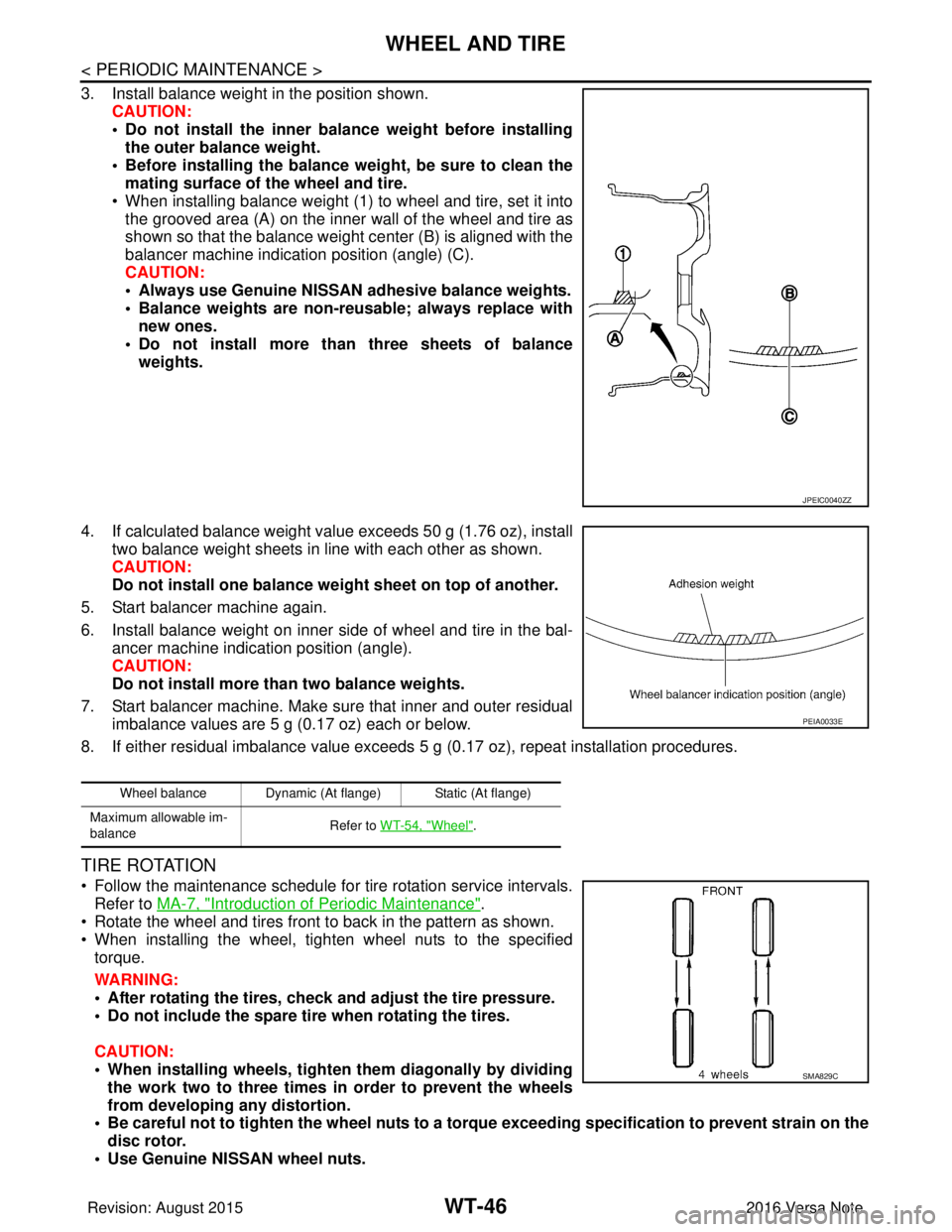
• When installing balance weight (1) to wheel and tire, set it into the grooved area (A) on the inner wall of the wheel and tire as
shown so that the balance weight center (B) is aligned with the
balancer machine indication position (angle) (C).
CAUTION:
• Always use Genuine NISSAN adhesive balance weights.
• Balance weights are non-reusable; always replace withnew ones.
• Do not install more than three sheets of balance weights.
4. If calculated balance weight value exceeds 50 g (1.76 oz), install two balance weight sheets in line with each other as shown.
CAUTION:
Do not install one balance weight sheet on top of another.
5. Start balancer machine again.
6. Install balance weight on inner side of wheel and tire in the bal- ancer machine indication position (angle).
CAUTION:
Do not install more than two balance weights.
7. Start balancer machine. Make sure that inner and outer residual imbalance values are 5 g (0.17 oz) each or below.
8. If either residual imbalance value exceeds 5 g (0.17 oz), repeat installation procedures.
TIRE ROTATION
• Follow the maintenance schedule for tire rotation service intervals.
Refer to MA-7, "
Introduction of Periodic Maintenance".
• Rotate the wheel and tires front to back in the pattern as shown.
• When installing the wheel, tighten wheel nuts to the specified torque.
WARNING:
• After rotating the tires, check and adjust the tire pressure.
• Do not include the spare tire when rotating the tires.
CAUTION:
• When installing wheels, tighten them diagonally by dividing
the work two to three times in order to prevent the wheels
from developing any distortion.
• Be careful not to tighten the wh eel nuts to a torque exceeding speci fication to prevent strain on the
disc rotor.
• Use Genuine NISSAN wheel nuts.
JPEIC0040ZZ
Wheel balance Dynamic (At flange) Static (At flange)
Maximum allowable im-
balance Refer to WT-54, "
Wheel".
PEIA0033E
SMA829C
Revision: August 2015
2016 Versa Note
cardiagn.com
Page 2790 of 3641

WHEEL AND TIREWT-47
< PERIODIC MAINTENANCE >
C
DF
G H
I
J
K L
M A
B
WT
N
O P
• Perform the ID registration after tire rotation. Refer to WT-22, "Work Procedure".
Wheel nut tightening
torque
:
WT-48, "
Exploded View"
Revision: August 2015 2016 Versa Note
cardiagn.com
Page 2794 of 3641
TRANSMITTERWT-51
< REMOVAL AND INSTALLATION >
C
DF
G H
I
J
K L
M A
B
WT
N
O P
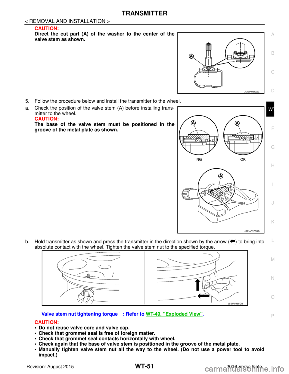
CAUTION:
Direct the cut part (A) of the washer to the center of the
valve stem as shown.
5. Follow the procedure below and install the transmitter to the wheel.
a. Check the position of the valve stem (A) before installing trans-
mitter to the wheel.
CAUTION:
The base of the valve stem mu st be positioned in the
groove of the metal plate as shown.
b. Hold transmitter as shown and press the transmitter in the direction shown by the arrow ( ) to bring into absolute contact with the wheel. Tighten the valve stem nut to the specified torque.
CAUTION:
• Do not reuse valve core and valve cap.
• Check that grommet seal is free of foreign matter.
• Check that grommet seal contacts horizontally with wheel.
• Check again that the base of valve stem is po sitioned in the groove of the metal plate.
• Manually tighten valve stem nut all the way to the wheel. (Do not use a power tool to avoid
impact.)
JMEIA0212ZZ
JSEIA0376GB
Valve stem nut tightening torque : Refer to WT-49, "Exploded View".
JSEIA0465GB
Revision: August 2015 2016 Versa Note
cardiagn.com
Page 2795 of 3641
WT-52
< REMOVAL AND INSTALLATION >
TRANSMITTER
• Do not tighten valve stem nut to more than the specified torque. It may cause grommet seal dam-age.
• Do not tighten valve stem nut to less than th e specified torque. It may cause an air leak.
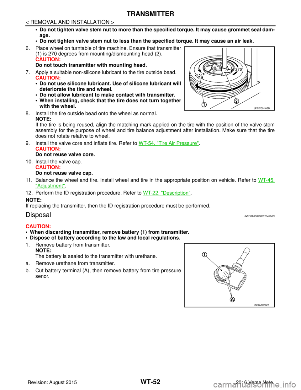
6. Place wheel on turntable of tire machine. Ensure that transmitter (1) is 270 degrees from mounting/dismounting head (2).
CAUTION:
Do not touch transmitter with mounting head.
7. Apply a suitable non-silicone lubricant to the tire outside bead. CAUTION:
• Do not use silicone lubricant. Use of silicone lubricant will
deteriorate the tire and wheel.
• Do not allow lubricant to make contact with transmitter.
• When installing, check that the tire does not turn together with the wheel.
8. Install the tire outside bead onto the wheel as normal. NOTE:
If the tire is being reused, align the matching mark applied on the tire with the position of the valve stem
assembly for the purpose of wheel and tire balance adjus tment after installation. Make sure that the tire
does not rotate relative to wheel.
9. Install the valve core and inflate tire. Refer to WT-54, "
Tire Air Pressure".
CAUTION:
Do not reuse valve core.
10. Install the valve cap. CAUTION:
Do not reuse valve cap.
11. Balance the wheel and tire. Install wheel and tire in the appropriate position on vehicle. Refer to WT-45,
"Adjustment".
12. Perform the ID registration procedure. Refer to WT-22, "
Description".
NOTE:
If replacing the transmitter, then the ID registration procedure must be performed.
DisposalINFOID:0000000012432471
CAUTION:
• When discarding transmitter, remove battery (1) from transmitter.
• Dispose of battery according to the law and local regulations.
1. Remove battery from transmitter. NOTE:
The battery is sealed to the transmitter with urethane.
a. Remove urethane from transmitter.
b. Cut battery terminal (A), then remove battery from tire pressure senor.
JPEIC0014GB
JSEIA0729ZZ
Revision: August 2015 2016 Versa Note
cardiagn.com