2016 NISSAN NOTE wheel torque
[x] Cancel search: wheel torquePage 1111 of 3641
![NISSAN NOTE 2016 Service Repair Manual EM-110
< UNIT DISASSEMBLY AND ASSEMBLY >[HR16DE]
CYLINDER BLOCK
• Measure the deflection of flywheel contact surface to torque with a
suitable tool (A).
• Measure the deflection at 210 mm (8.27 in NISSAN NOTE 2016 Service Repair Manual EM-110
< UNIT DISASSEMBLY AND ASSEMBLY >[HR16DE]
CYLINDER BLOCK
• Measure the deflection of flywheel contact surface to torque with a
suitable tool (A).
• Measure the deflection at 210 mm (8.27 in](/manual-img/5/57363/w960_57363-1110.png)
EM-110
< UNIT DISASSEMBLY AND ASSEMBLY >[HR16DE]
CYLINDER BLOCK
• Measure the deflection of flywheel contact surface to torque with a
suitable tool (A).
• Measure the deflection at 210 mm (8.27 in) diameter.
• If measured value is out of the standard, replace flywheel.
• If a trace of burn or discoloration is found on the surface, clean it with sandpaper.
CAUTION:
When measuring, keep magnetic fields (such as dial indicator
stand) away from signal plate of the rear end of crankshaft.
Limit : 0.45 mm (0.0177 in) or less.
PBIC4006E
Revision: August 2015
2016 Versa Note
cardiagn.com
Page 1830 of 3641
FRONT WHEEL HUB AND KNUCKLEFAX-13
< REMOVAL AND INSTALLATION >
CEF
G H
I
J
K L
M A
B
FA X
N
O P
5. Perform inspection after assembly. Refer to FAX-13, "Inspection".
InspectionINFOID:0000000012431893
INSPECTION AFTER REMOVAL
Check the following items, and replace the part if necessary.
• Check components for deformation, cracks, and other damage.
• Check boots of transverse link and steering outer so cket ball joint for breakage, axial end play, and swing
torque. Refer to FSU-10, "
Inspection" and FSU-20, "Ball Joint".
INSPECTION AFTER DISASSEMBLY
Wheel Hub
• Check wheel hub for cracks (with magnetic exploration or dye testing). Replace if necessary.
Steering Knuckle
• Check steering knuckle for deformation, cracks, and other damage. Replace if any non-standard conditions
are found.
Snap Rings
• Check snap ring for wear or cracks. Replace if necessary.
INSPECTION AFTER ASSEMBLY
Check wheel bearing rotating torque as per the following instructions.
NOTE:
The adequacy of turning torque can be judged from a measurement value by a spring balancer.
1. For a proper fit of the bearing, turn the wheel hub clockwise and counterclockwise, respectively, 10 times
or more with a press-fit load applied.
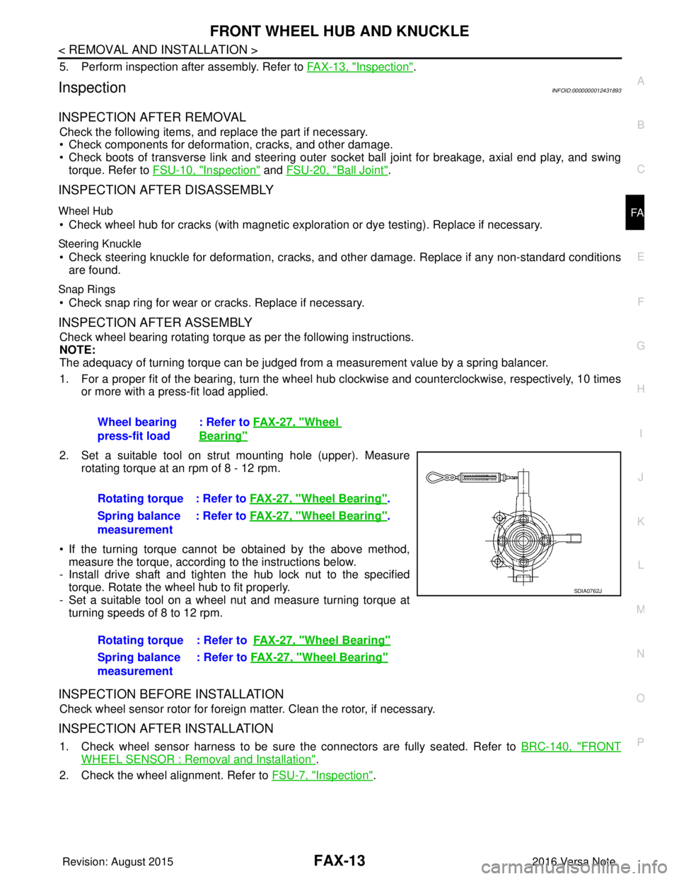
2. Set a suitable tool on strut mounting hole (upper). Measure rotating torque at an rpm of 8 - 12 rpm.
• If the turning torque cannot be obtained by the above method, measure the torque, according to the instructions below.
- Install drive shaft and tighten the hub lock nut to the specified
torque. Rotate the wheel hub to fit properly.
- Set a suitable tool on a wheel nut and measure turning torque at turning speeds of 8 to 12 rpm.
INSPECTION BEFORE INSTALLATION
Check wheel sensor rotor for foreign matter. Clean the rotor, if necessary.
INSPECTION AFTER INSTALLATION
1. Check wheel sensor harness to be sure the connectors are fully seated. Refer to BRC-140, "FRONT
WHEEL SENSOR : Removal and Installation".
2. Check the wheel alignment. Refer to FSU-7, "
Inspection".
Wheel bearing
press-fit load
: Refer to
FAX-27, "
Wheel
Bearing"
Rotating torque : Refer to FAX-27, "Wheel Bearing".
Spring balance
measurement : Refer to
FAX-27, "
Wheel Bearing".
Rotating torque : Refer to FAX-27, "
Wheel Bearing"
Spring balance
measurement: Refer to
FAX-27, "Wheel Bearing"
SDIA0762J
Revision: August 2015 2016 Versa Note
cardiagn.com
Page 1832 of 3641

FRONT DRIVE SHAFT BOOTFAX-15
< REMOVAL AND INSTALLATION >
CEF
G H
I
J
K L
M A
B
FA X
N
O P
WHEEL SIDE : Removal and InstallationINFOID:0000000012431895
REMOVAL
1. Remove the wheel and tire using power tool. Refer to WT-48, "Removal and Installation".
2. Remove the brake caliper torque member bolts, leav ing the brake hose attached. Position the brake cali-
per aside with wire. Refer to BR-37, "
BRAKE CALIPER ASSEMBLY : Removal and Installation".
CAUTION:
Do not depress the brake pedal while the brake caliper is removed.
3. Put alignment marks on the disc brake rotor and on the wheel hub. Remove the disc brake rotor.
CAUTION:
Do not drop the disc brake rotor.
4. Remove the wheel sensor bolt. Position the wheel sensor and the wheel sensor harness aside. Refer to
BRC-140, "
FRONT WHEEL SENSOR : Removal and Installation".
5. Remove the cotter pin from the drive shaft.
6. Hold the wheel hub using Tool. Loosen the wheel hub lock nut.
7. Using a piece of wood and a suitable tool, tap on the wheel hub lock nut to disengage the drive shaft from the wheel hub.
CAUTION:
• Do not place the drive shaft joint at an extreme angle. Also be careful not to overextend slide
joint.
• Do not allow the drive shaft to hang down without support.
NOTE:
Use a suitable puller if the drive shaft cannot be separated from the wheel hub even after performing the
above procedure.
8. Remove the wheel hub lock nut.
9. Remove the nut and bolt from the lower ball joint. Disconnect the steering knuckle from the transverse
link.
10. Remove the drive shaft from the wheel hub.
11. Remove the boot bands.
12. Separate the boot from the joint sub-assembly.
13. Screw a suitable tool (A) into the joint sub-assembly screw part to a length of 30 mm (1.18 in) or more. Support the drive shaft
with one hand and pull out the joint sub-assembly from the shaft.
CAUTION:
• Align the suitable tool an d the drive shaft. Remove the
joint sub-assembly by pull ing firmly and uniformly.
• If the joint sub-assembly cannot be pulled out, try after removing the drive shaft from the vehicle. Refer to FA X -
22, "Disassembly and Assembly".
14. Remove the circular clip (1) from the shaft.
15. Remove the outer boot from the shaft. Tool number : KV4010104000 ( — )
JPDIF0258ZZ
JPDIF0007ZZ
Revision: August 2015
2016 Versa Note
cardiagn.com
Page 1835 of 3641
FAX-18
< REMOVAL AND INSTALLATION >
FRONT DRIVE SHAFT BOOT
• Check each mating surface for water and foreign matter. If there is any water or foreign matter,
clean the mating surface.
17. Install the transverse link to the steering knuckle with the nut and bolt. Refer to FSU-10, "
Exploded View".
18. Hold the wheel hub using a Tool. Tighten the wheel hub lock nut. CAUTION:
• Since the drive shaft is assembled by press-fitting, use a torque wrench to tighten the wheel hub
lock nut. Do not use a power tool.
• Too much torque causes axle noise. Too little torque causes wheel bearing looseness. Tighten the wheel hub lock nut to the specification.
19. Install the cotter pin. Securely bend the cotter pin to prevent rattles. CAUTION:
Do not reuse the cotter pin.
20. Install the wheel sensor, the wheel sensor bolt, and the wheel sensor harness. Refer to BRC-140,
"FRONT WHEEL SENSOR : Removal and Installation".
21. Align the matching marks on the disc brake roto r and on the wheel hub. Install the disc brake rotor.
CAUTION:
Do not drop the disc brake rotor.
22. Remove the wire from the brake caliper. Install the brake caliper and the brake caliper torque member
bolts. Refer to BR-37, "
BRAKE CALIPER ASSEMBLY : Removal and Installation".
CAUTION:
Do not twist the brake hose.
23. Install the wheel and tire. Refer to WT-48, "
Removal and Installation".
24. Complete the inspection. Refer to FAX-18, "
Inspection".
TRANSAXLE SIDE
TRANSAXLE SIDE : Removal and InstallationINFOID:0000000012431896
Remove boot after drive shaft is removed from the vehicle.
• For drive shaft removal and installation, refer to FAX-19, "
Removal and Installation".
• For drive shaft disassembly and assembly, refer to FAX-22, "
Disassembly and Assembly".
InspectionINFOID:0000000012431897
INSPECTION AFTER INSTALLATION
1. Check the wheel sensor harness to be sure the connectors are fully seated.
2. Check the wheel alignment. Refer to FSU-7, "
Inspection".
Tool number : KV4010104000 ( — )
Revision: August 2015
2016 Versa Note
cardiagn.com
Page 1844 of 3641
SERVICE DATA AND SPECIFICATIONS (SDS)FAX-27
< SERVICE DATA AND SPECIFICATIONS (SDS)
CEF
G H
I
J
K L
M A
B
FA X
N
O P
SERVICE DATA AND SPECIFICATIONS (SDS)
SERVICE DATA AND SPECIFICATIONS (SDS)
Wheel BearingINFOID:0000000012431902
Drive ShaftINFOID:0000000012431903
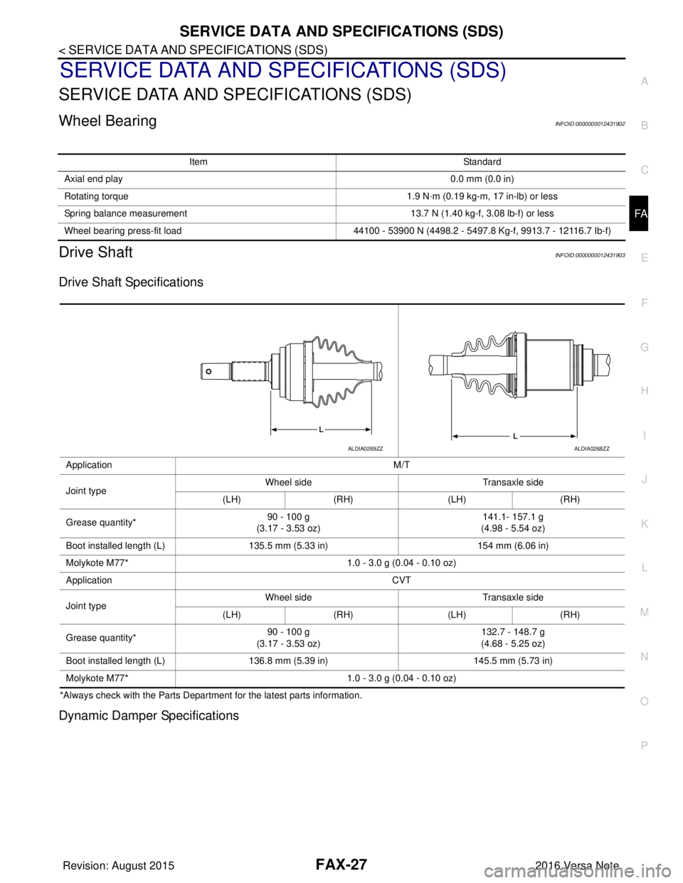
Drive Shaft Specifications
*Always check with the Parts Departme nt for the latest parts information.
Dynamic Damper Specifications
Item Standard
Axial end play 0.0 mm (0.0 in)
Rotating torque 1.9 N·m (0.19 kg-m, 17 in-lb) or less
Spring balance measurement 13.7 N (1.40 kg-f, 3.08 lb-f) or less
Wheel bearing press-fit load 44100 - 53900 N (4498.2 - 5497.8 Kg-f, 9913.7 - 12116.7 Ib-f)
Application M/T
Joint type Wheel side
Transaxle side
(LH) (RH) (LH)(RH)
Grease quantity* 90 - 100 g
(3.17 - 3.53 oz) 141.1- 157.1 g
(4.98 - 5.54 oz)
Boot installed length (L) 135.5 mm (5.33 in) 154 mm (6.06 in)
Molykote M77* 1.0 - 3.0 g (0.04 - 0.10 oz)
Application CVT
Joint type Wheel side
Transaxle side
(LH) (RH) (LH)(RH)
Grease quantity* 90 - 100 g
(3.17 - 3.53 oz) 132.7 - 148.7 g
(4.68 - 5.25 oz)
Boot installed length (L) 136.8 mm (5.39 in) 145.5 mm (5.73 in)
Molykote M77* 1.0 - 3.0 g (0.04 - 0.10 oz)
ALDIA0269ZZALDIA0268ZZ
Revision: August 2015 2016 Versa Note
cardiagn.com
Page 1847 of 3641
FSU-2
< PRECAUTION >
PRECAUTIONS
PRECAUTION
PRECAUTIONS
Precaution for Supplemental Restraint System (SRS) "AIR BAG" and "SEAT BELT
PRE-TENSIONER"
INFOID:0000000012430294
The Supplemental Restraint System such as “A IR BAG” and “SEAT BELT PRE-TENSIONER”, used along
with a front seat belt, helps to reduce the risk or severity of injury to the driver and front passenger for certain
types of collision. Information necessary to service the system safely is included in the SR and SB section of
this Service Manual.
WARNING:
• To avoid rendering the SRS inopera tive, which could increase the risk of personal injury or death in
the event of a collision which would result in air bag inflation, all maintenance must be performed by
an authorized NISSAN/INFINITI dealer.
• Improper maintenance, including in correct removal and installation of the SRS, can lead to personal
injury caused by unintent ional activation of the system. For re moval of Spiral Cable and Air Bag
Module, see the SR section.
• Do not use electrical test equipmen t on any circuit related to the SRS unless instructed to in this
Service Manual. SRS wiring harn esses can be identified by yellow and/or orange harnesses or har-
ness connectors.
PRECAUTIONS WHEN USING POWER TOOLS (AIR OR ELECTRIC) AND HAMMERS
WARNING:
• When working near the Airbag Diagnosis Sensor Unit or other Airbag System sensors with the Igni-
tion ON or engine running, DO NOT use air or electri c power tools or strike near the sensor(s) with a
hammer. Heavy vibration could activate the sensor( s) and deploy the air bag(s), possibly causing
serious injury.
• When using air or electric power tools or hammers , always switch the Ignition OFF, disconnect the
battery and wait at least three minutes before performing any service.
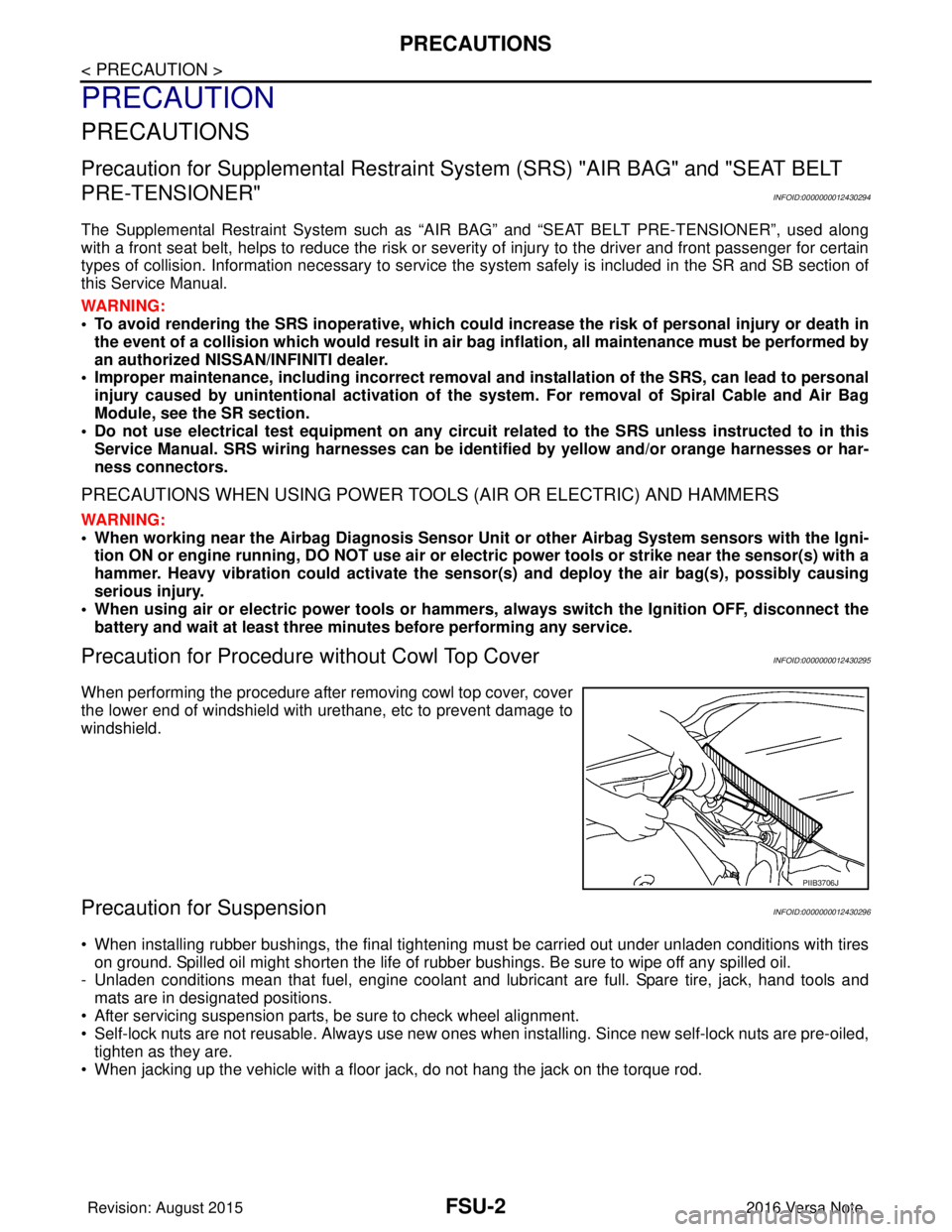
Precaution for Procedure without Cowl Top CoverINFOID:0000000012430295
When performing the procedure after removing cowl top cover, cover
the lower end of windshield with urethane, etc to prevent damage to
windshield.
Precaution for SuspensionINFOID:0000000012430296
• When installing rubber bushings, the final tightening mu st be carried out under unladen conditions with tires
on ground. Spilled oil might shorten the life of rubber bushings. Be sure to wipe off any spilled oil.
- Unladen conditions mean that fuel, engine coolant and lubricant are full. Spare tire, jack, hand tools and mats are in designated positions.
• After servicing suspension parts, be sure to check wheel alignment.
• Self-lock nuts are not reusable. Always use new ones when installing. Since new self-lock nuts are pre-oiled,
tighten as they are.
• When jacking up the vehicle with a floor jack, do not hang the jack on the torque rod.
PIIB3706J
Revision: August 2015 2016 Versa Note
cardiagn.com
Page 1854 of 3641
FRONT COIL SPRING AND STRUTFSU-9
< REMOVAL AND INSTALLATION >
C
DF
G H
I
J
K L
M A
B
FSU
N
O P
REMOVAL AND INSTALLATION
FRONT COIL SPRING AND STRUT
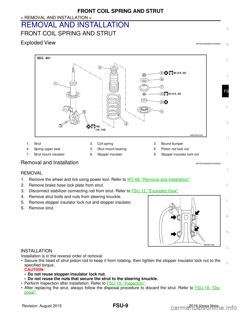
Exploded ViewINFOID:0000000012430303
Removal and InstallationINFOID:0000000012430304
REMOVAL
1. Remove the wheel and tire using power tool. Refer to WT-48, "Removal and Installation".
2. Remove brake hose lock plate from strut.
3. Disconnect stabilizer connecting rod from strut. Refer to FSU-12, "
Exploded View".
4. Remove strut bolts and nuts from steering knuckle.
5. Remove stopper insulator lock nut and stopper insulator.
6. Remove strut.
INSTALLATION
Installation is in the reverse order of removal.
• Secure the head of strut piston rod to keep it from rotating, then tighten the stopper insulator lock nut to the specified torque.
CAUTION:
• Do not reuse stopper insulator lock nut.
• Do not reuse the nuts that secure the strut to the steering knuckle.
• Perform inspection after installation. Refer to FSU-19, "
Inspection".
• After replacing the strut, always follow the dis posal procedure to discard the strut. Refer to FSU-19, "
Dis-
posal".
1. Strut2. Coil spring3. Bound bumper
4. Spring upper seat 5. Strut mount bearing6. Piston rod lock nut
7. Strut mount insulator 8. Stopper insulator9. Stopper insulator lock nut
AWEIA0418ZZ
WEIA0179E
Revision: August 2015 2016 Versa Note
cardiagn.com
Page 1855 of 3641
FSU-10
< REMOVAL AND INSTALLATION >
TRANSVERSE LINK
TRANSVERSE LINK
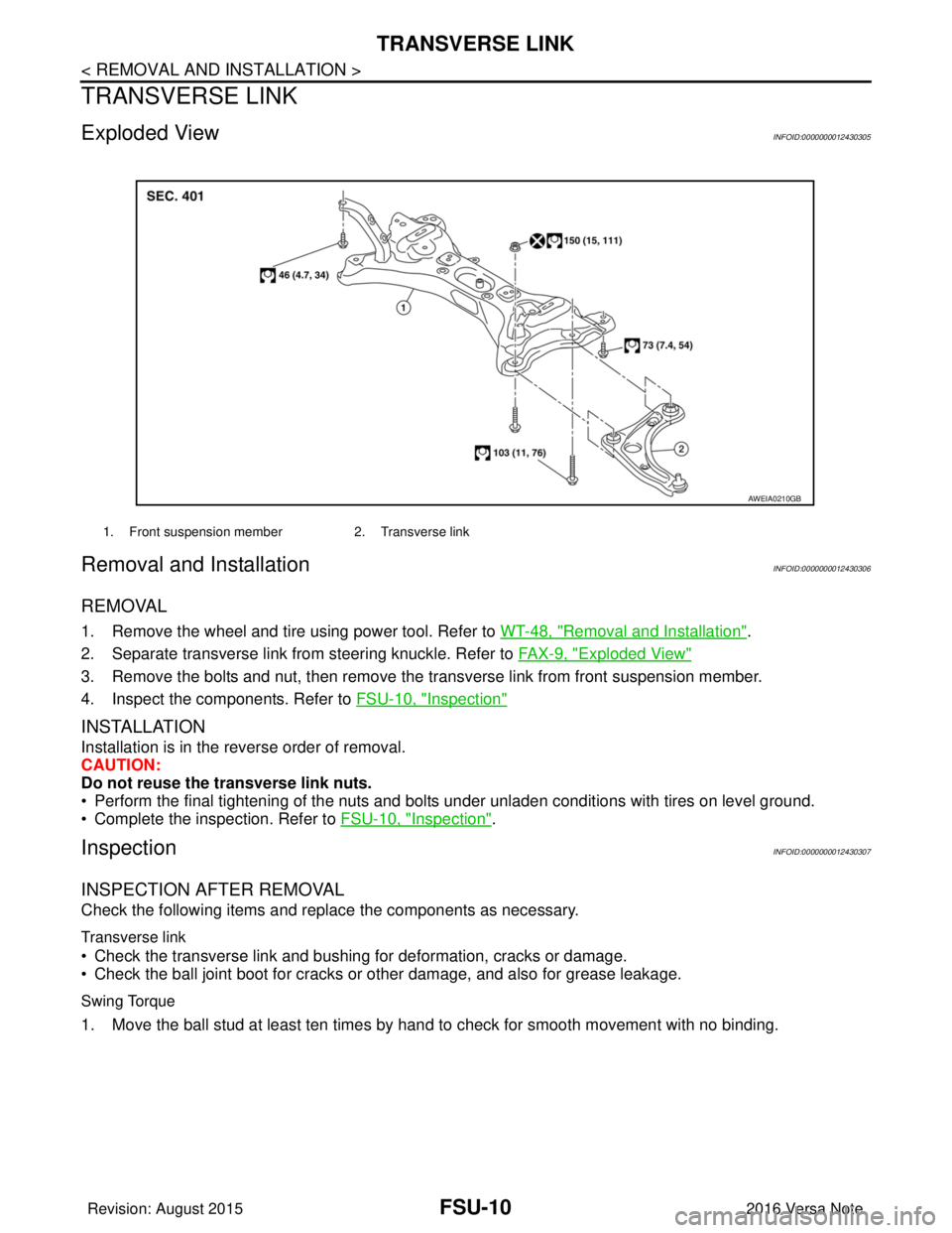
Exploded ViewINFOID:0000000012430305
Removal and InstallationINFOID:0000000012430306
REMOVAL
1. Remove the wheel and tire using power tool. Refer to WT-48, "Removal and Installation".
2. Separate transverse link from steering knuckle. Refer to FA X - 9 , "
Exploded View"
3. Remove the bolts and nut, then remove the transverse link from front suspension member.
4. Inspect the components. Refer to FSU-10, "
Inspection"
INSTALLATION
Installation is in the reverse order of removal.
CAUTION:
Do not reuse the transverse link nuts.
• Perform the final tightening of the nuts and bolts under unladen conditions with tires on level ground.
• Complete the inspection. Refer to FSU-10, "
Inspection".
InspectionINFOID:0000000012430307
INSPECTION AFTER REMOVAL
Check the following items and replace the components as necessary.
Transverse link
• Check the transverse link and bushing for deformation, cracks or damage.
• Check the ball joint boot for cracks or other damage, and also for grease leakage.
Swing Torque
1. Move the ball stud at least ten times by hand to check for smooth movement with no binding.
1. Front suspension member2. Transverse link
AWEIA0210GB
Revision: August 2015 2016 Versa Note
cardiagn.com