2016 NISSAN NOTE wheel torque
[x] Cancel search: wheel torquePage 3232 of 3641

STEERING COLUMNST-11
< REMOVAL AND INSTALLATION >
C
DE
F
H I
J
K L
M A
B
ST
N
O P
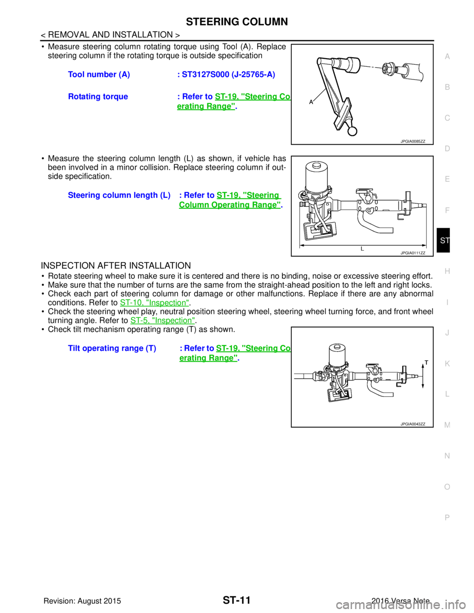
• Measure steering column rotating torque using Tool (A). Replace steering column if the rotating torque is outside specification
• Measure the steering column length (L) as shown, if vehicle has been involved in a minor collision. Replace steering column if out-
side specification.
INSPECTION AFTER INSTALLATION
• Rotate steering wheel to make sure it is centered and there is no binding, noise or excessive steering effort.
• Make sure that the number of turns are the same from the straight-ahead position to the left and right locks.
• Check each part of steering column for damage or other malfunctions. Replace if there are any abnormal
conditions. Refer to ST-10, "
Inspection".
• Check the steering wheel play, neutral position steering wheel, steering wheel turning force, and front wheel turning angle. Refer to ST-5, "
Inspection".
• Check tilt mechanism operating range (T) as shown. Tool number (A)
: ST3127S000 (J-25765-A)
Rotating torque : Refer to ST-19, "
Steering Column Op-
erating Range".
JPGIA0085ZZ
Steering column length (L) : Refer to ST-19, "Steering
Column Operating Range".
JPGIA0111ZZ
Tilt operating range (T) : Refer to ST-19, "Steering Column Op-
erating Range".
JPGIA0043ZZ
Revision: August 2015 2016 Versa Note
cardiagn.com
Page 3238 of 3641

STEERING GEAR AND LINKAGEST-17
< UNIT DISASSEMBLY AND ASSEMBLY >
C
DE
F
H I
J
K L
M A
B
ST
N
O P
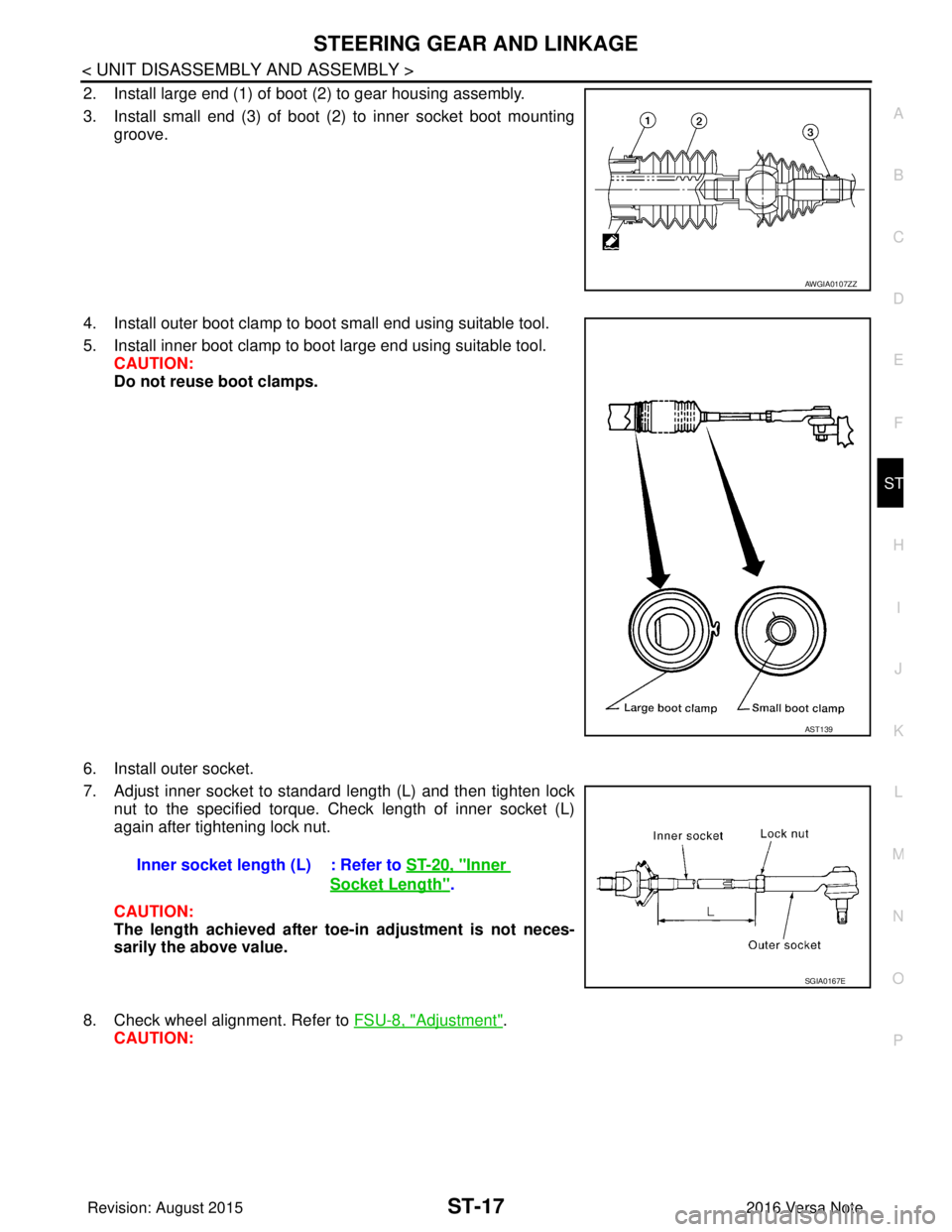
2. Install large end (1) of boot (2) to gear housing assembly.
3. Install small end (3) of boot (2) to inner socket boot mounting groove.
4. Install outer boot clamp to boot small end using suitable tool.
5. Install inner boot clamp to boot large end using suitable tool. CAUTION:
Do not reuse boot clamps.
6. Install outer socket.
7. Adjust inner socket to standard length (L) and then tighten lock nut to the specified torque. Check length of inner socket (L)
again after tightening lock nut.
CAUTION:
The length achieved after toe-in adjustment is not neces-
sarily the above value.
8. Check wheel alignment. Refer to FSU-8, "
Adjustment".
CAUTION:
AWGIA0107ZZ
AST139
Inner socket length (L) : Refer to ST-20, "Inner
Socket Length".
SGIA0167E
Revision: August 2015 2016 Versa Note
cardiagn.com
Page 3240 of 3641

SERVICE DATA AND SPECIFICATIONS (SDS)ST-19
< SERVICE DATA AND SPECIFICATIONS (SDS)
C
DE
F
H I
J
K L
M A
B
ST
N
O P
SERVICE DATA AND SPECIFICATIONS (SDS)
SERVICE DATA AND SPECIFICATIONS (SDS)
General SpecificationsINFOID:0000000012430513
Steering Wheel Axial End Play and PlayINFOID:0000000012430514
Unit: mm (in)
Steering Wheel Turning ForceINFOID:0000000012430515
Unit: N (kg-f, lb-f)
Steering AngleINFOID:0000000012430516
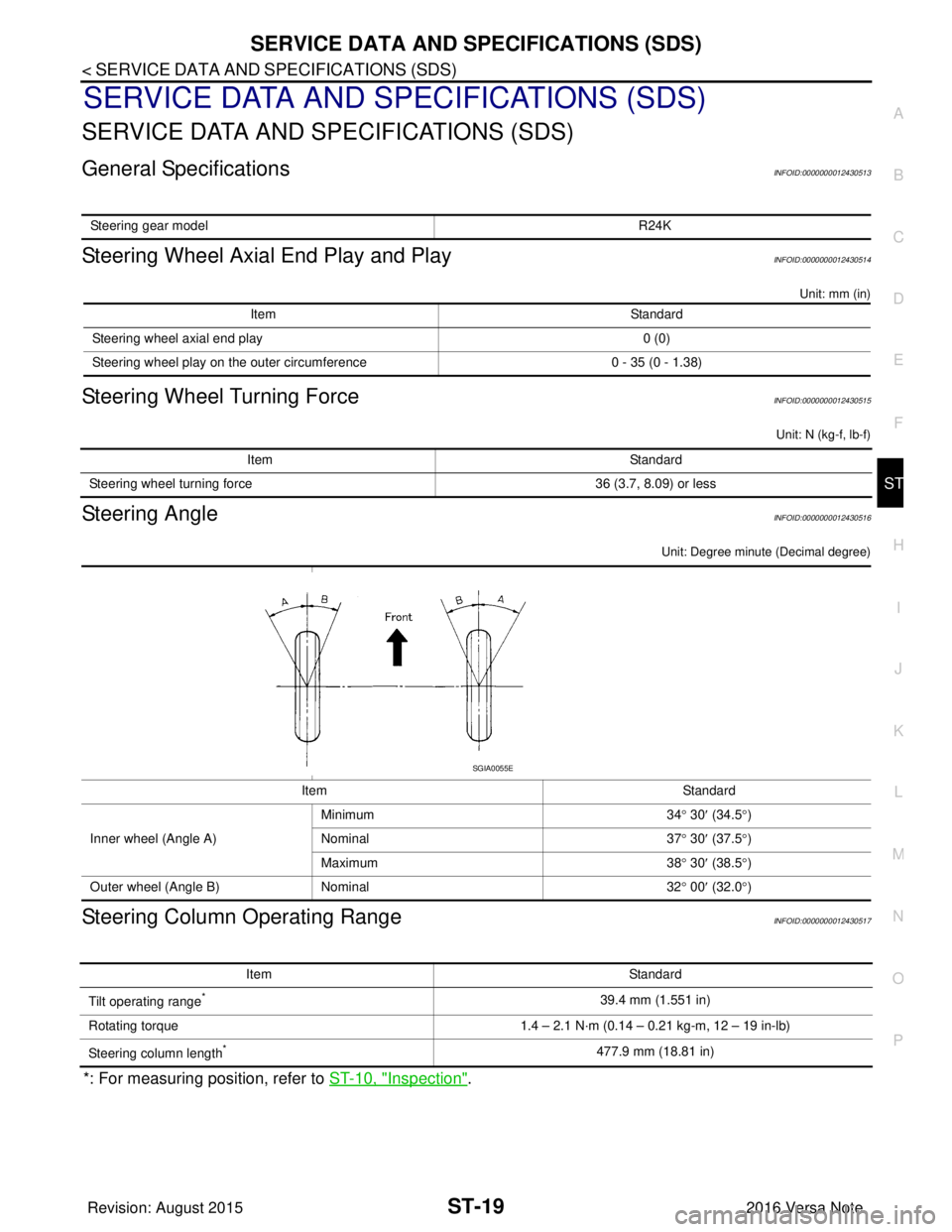
Unit: Degree minute (Decimal degree)
Steering Column Operating RangeINFOID:0000000012430517
*: For measuring position, refer to ST-10, "Inspection".
Steering gear model R24K
ItemStandard
Steering wheel axial end play 0 (0)
Steering wheel play on the outer circumference 0 - 35 (0 - 1.38)
ItemStandard
Steering wheel turning force 36 (3.7, 8.09) or less
ItemStandard
Inner wheel (Angle A) Minimum
34° 30 ′ (34.5° )
Nominal 37° 30 ′ (37.5° )
Maximum 38° 30 ′ (38.5° )
Outer wheel (Angle B) Nominal 32° 00 ′ (32.0° )
SGIA0055E
Item Standard
Tilt operating range
*39.4 mm (1.551 in)
Rotating torque 1.4 – 2.1 N·m (0.14 – 0.21 kg-m, 12 – 19 in-lb)
Steering column length
*477.9 mm (18.81 in)
Revision: August 2015 2016 Versa Note
cardiagn.com
Page 3322 of 3641
![NISSAN NOTE 2016 Service Repair Manual SYSTEMTM-81
< SYSTEM DESCRIPTION > [CVT: RE0F11A]
C
EF
G H
I
J
K L
M A
B
TM
N
O P
CONTROL WHEN FLUID TEMPERATURE IS HIGH
TORQUE IS REDUCED WHEN DRIVING WITH THE REVERSE GEAR
REVERSE PROHIBIT CONTROL
L NISSAN NOTE 2016 Service Repair Manual SYSTEMTM-81
< SYSTEM DESCRIPTION > [CVT: RE0F11A]
C
EF
G H
I
J
K L
M A
B
TM
N
O P
CONTROL WHEN FLUID TEMPERATURE IS HIGH
TORQUE IS REDUCED WHEN DRIVING WITH THE REVERSE GEAR
REVERSE PROHIBIT CONTROL
L](/manual-img/5/57363/w960_57363-3321.png)
SYSTEMTM-81
< SYSTEM DESCRIPTION > [CVT: RE0F11A]
C
EF
G H
I
J
K L
M A
B
TM
N
O P
CONTROL WHEN FLUID TEMPERATURE IS HIGH
TORQUE IS REDUCED WHEN DRIVING WITH THE REVERSE GEAR
REVERSE PROHIBIT CONTROL
LINE PRESSURE CONTROL
Vehicle behavior in
control If the accelerator is kept depressing during wheel spin, the engine revolution and vehicle speed are limited to
a certain degree. From the 1GR, upshift to a certain gear ratio is only allowed.
Normal return condi-
tion Wheel spin convergence returns the control to the normal control.
ControlWhen the CVT fluid temperature is high, the gear shift permission maximum revolution and the maximum
torque are reduced than usual to prevent increase of the oil temperature.
Vehicle behavior in
control Power performance may be lowered, compared to normal control.
Normal return condi-
tion The control returns to the normal control when CVT fluid temperature is lowered.
Control
Engine output is controlled according to a vehicle speed while reversing the vehicle.
Vehicle behavior in
control Power performance may be lowered while reversing the vehicle.
Normal return condi-
tion Torque returns to normal by positioning the selector lever in a range ot
her than “R” position.
ControlThe reverse brake is controlled to avoid becoming engaged when the selector lever is set in “R” position while
driving in forward direction at more than the specified speed.
Vehicle behavior in
control If the selector lever is put at “R” position when driving with the forward gear, the gear becomes neutral, not
reverse.
Normal return condi-
tion The control returns to normal control when the vehicle is driven at low speeds. (The reverse brake becomes
engaged.)
Revision: August 2015
2016 Versa Note
cardiagn.com
Page 3350 of 3641
![NISSAN NOTE 2016 Service Repair Manual TCM
TM-109
< ECU DIAGNOSIS INFORMATION > [CVT: RE0F11A]
C
EF
G H
I
J
K L
M A
B
TM
N
O P
Protection Control INFOID:0000000012431035
The TCM becomes the protection control status temporarily to protect NISSAN NOTE 2016 Service Repair Manual TCM
TM-109
< ECU DIAGNOSIS INFORMATION > [CVT: RE0F11A]
C
EF
G H
I
J
K L
M A
B
TM
N
O P
Protection Control INFOID:0000000012431035
The TCM becomes the protection control status temporarily to protect](/manual-img/5/57363/w960_57363-3349.png)
TCM
TM-109
< ECU DIAGNOSIS INFORMATION > [CVT: RE0F11A]
C
EF
G H
I
J
K L
M A
B
TM
N
O P
Protection Control INFOID:0000000012431035
The TCM becomes the protection control status temporarily to protect the safety when the safety of TCM and
transmission is lost. It automatically returns to the normal status if the safety is secured.
The TCM has the following protection control.
CONTROL FOR WHEEL SPIN
CONTROL WHEN FLUID TEMPERATURE IS HIGH
TORQUE IS REDUCED WHEN DRIVING WITH THE REVERSE GEAR
REVERSE PROHIBIT CONTROL
DTC Inspection Priority ChartINFOID:0000000012431036
If multiple malfunction codes are detected at the same time, check each code according to the DTC check pri-
ority list below.
Control When a wheel spin is detected, the engine output and gear ratio are limited and the line pressure is increased.
At the 1GR, the clutch pressure is increased.
Vehicle behavior in
control If the accelerator is kept depressing during wheel spin, the engine revolution and vehicle speed are limited to
a certain degree. From the 1GR, upshift to a certain gear ratio is only allowed.
Normal return condi-
tion Wheel spin convergence returns the control to the normal control.
ControlWhen the CVT fluid temperature is high, the gear shift permission maximum revolution and the maximum
torque are reduced than usual to prevent increase of the oil temperature.
Vehicle behavior in
control Power performance may be lowered, compared to normal control.
Normal return condi-
tion The control returns to the normal control when CVT fluid temperature is lowered.
Control
Engine output is controlled according to a vehicle speed while reversing the vehicle.
Vehicle behavior in
control Power performance may be lowered while reversing the vehicle.
Normal return condi-
tion Torque returns to normal by positioning the selector lever in a range ot
her than “R” position.
ControlThe reverse brake is controlled to avoid becoming engaged when the selector lever is set in “R” position while
driving in forward direction at more than the specified speed.
Vehicle behavior in
control If the selector lever is put at “R” position when driving with the forward gear, the gear becomes neutral, not
reverse.
Normal return condi-
tion The control returns to normal control when the vehicle is driven at low speeds. (The reverse brake becomes
engaged.)
Priority
DTC (Diagnostic Trouble Code) Reference
1 P0863 CONTROL UNIT (CAN)
TM-181
U0073 COMM BUS A OFFTM-135
U0100 LOST COMM (ECM A)TM-136
U0140 LOST COMM (BCM)TM-137
U0141 LOST COMM (BCM A)TM-138
U0155 LOST COMM (IPC)TM-139
U0300 CAN COMM DATA TM-140
U1000 CAN COMM CIRCTM-141
U1117 LOST COMM (ABS)TM-142
Revision: August 2015 2016 Versa Note
cardiagn.com
Page 3374 of 3641
![NISSAN NOTE 2016 Service Repair Manual CVT POSITIONTM-133
< BASIC INSPECTION > [CVT: RE0F11A]
C
EF
G H
I
J
K L
M A
B
TM
N
O P
CVT POSITION
InspectionINFOID:0000000012431050
1. Turn ON the ignition switch with the shift selector in the "P" NISSAN NOTE 2016 Service Repair Manual CVT POSITIONTM-133
< BASIC INSPECTION > [CVT: RE0F11A]
C
EF
G H
I
J
K L
M A
B
TM
N
O P
CVT POSITION
InspectionINFOID:0000000012431050
1. Turn ON the ignition switch with the shift selector in the "P"](/manual-img/5/57363/w960_57363-3373.png)
CVT POSITIONTM-133
< BASIC INSPECTION > [CVT: RE0F11A]
C
EF
G H
I
J
K L
M A
B
TM
N
O P
CVT POSITION
InspectionINFOID:0000000012431050
1. Turn ON the ignition switch with the shift selector in the "P" position.
2. Press the shift selector handle button with the brak e pedal depressed, and confirm that the shift selector
can be moved from the "P" position. Also confirm that shift selector will not move from the "P" position
without depressing the brake pedal.
3. Move the shift selector and check for “excessive effort,” “sticking,” “noise” or “rattle”.
4. Confirm that shift selector stops at each position with the feel of engagement when it is moved through all
the positions. Check whether or not the actual position the shift selector is in matches the position shown
by the transaxle body.
5. The method of operating the shift selector to individual positions correctly should be as shown.
• (A): Press shift selector button to operate shift selector, whiledepressing the brake pedal.
• (B): Press shift selector button to operate shift selector.
• (C): Shift selector can be operated without pressing shift selector button.
6. When the shift selector handle button is pressed without apply- ing forward/backward force to the shift selector at “P”, “R”, “N”
and “D” positions, there should be no “sticking” of the button.
7. Confirm the back-up lamps illuminate only when shift selector is placed in the “R” position. Confirm the back-up lamps do not illu-
minate when the shift selector is pushed toward the “R” pos ition side when shift selector is in the “P” or “N”
position.
8. Check that the engine can be started only when the shift selector is in the “P” and “N” positions.
9. Check that the transaxle is locked when t he shift selector is in the "P" position.
AdjustmentINFOID:0000000012431051
1. Move the shift selector to the “P” position.
CAUTION:
Rotate the wheels at least a quarter turn and be certain the transaxle is locked in the "P" position.
2. Remove nut (A) and set manual lever (B) to the “P” position. CAUTION:
Do not apply force to the manual lever.
3. Tighten nuts to the specified torque. Refer to TM-234, "
Exploded
View".
CAUTION:
Do not move the manual lever when tightening.
WCIA0620E
JSDIA1875ZZ
Revision: August 2015 2016 Versa Note
cardiagn.com