2016 NISSAN NOTE wheel torque
[x] Cancel search: wheel torquePage 3118 of 3641

SR-2
< PRECAUTION >
PRECAUTIONS
PRECAUTION
PRECAUTIONS
Precaution for Supplemental Restraint System (SRS) "AIR BAG" and "SEAT BELT
PRE-TENSIONER"
INFOID:0000000012430560
The Supplemental Restraint System such as “A IR BAG” and “SEAT BELT PRE-TENSIONER”, used along
with a front seat belt, helps to reduce the risk or severity of injury to the driver and front passenger for certain
types of collision. Information necessary to service the system safely is included in the SR and SB section of
this Service Manual.
WARNING:
• To avoid rendering the SRS inopera tive, which could increase the risk of personal injury or death in
the event of a collision which would result in air bag inflation, all maintenance must be performed by
an authorized NISSAN/INFINITI dealer.
• Improper maintenance, including in correct removal and installation of the SRS, can lead to personal
injury caused by unintent ional activation of the system. For re moval of Spiral Cable and Air Bag
Module, see the SR section.
• Do not use electrical test equipmen t on any circuit related to the SRS unless instructed to in this
Service Manual. SRS wiring harn esses can be identified by yellow and/or orange harnesses or har-
ness connectors.
PRECAUTIONS WHEN USING POWER TOOLS (AIR OR ELECTRIC) AND HAMMERS
WARNING:
• When working near the Airbag Diagnosis Sensor Unit or other Airbag System sensors with the Igni-
tion ON or engine running, DO NOT use air or electri c power tools or strike near the sensor(s) with a
hammer. Heavy vibration could activate the sensor( s) and deploy the air bag(s), possibly causing
serious injury.
• When using air or electric power tools or hammers , always switch the Ignition OFF, disconnect the
battery and wait at least three minutes before performing any service.
ServiceINFOID:0000000012430561
• Do not use electrical test equipment to check SRS ci rcuits unless instructed to in this Service Manual.
• Before servicing the SRS, turn ignition switch OFF, disconnect both battery cables and wait at least three
minutes.
For approximately three minutes after the cables are remo ved, it is still possible for the air bag and seat belt
pre-tensioner to deploy. Therefore, do not work on any SRS connectors or wires until at least three minutes
have passed.
• Diagnosis sensor unit must always be installed with their arrow marks “ ⇐” pointing towards the front of the
vehicle for proper operation. Also chec k diagnosis sensor unit for cracks, deformities or rust before installa-
tion and replace as required.
• The spiral cable must be aligned with the neutral position since its rotations are limited. Do not turn steering wheel and column after removal of steering gear.
• Handle air bag module carefully. Always place driver and front passenger air bag modules with the pad side facing upward and seat mounted front side air bag module standing with the stud bolt side facing down.
• Conduct self-diagnosis to check entire SRS for proper function after replacing any components.
• After air bag inflates, the instrument panel assembly should be replaced if damaged.
• Always replace instrument panel pad following front passenger air bag deployment.
Precaution for WorkINFOID:0000000012430562
• When removing or disassembling each component, be careful not to damage or deform it. If a component may be subject to interference, be sure to protect it with a shop cloth.
• When removing (disengaging) components with a screwdriver or similar tool, be sure to wrap the component with a shop cloth or vinyl tape to protect it.
• Protect the removed parts with a shop cloth and prevent them from being dropped.
• Replace a deformed or damaged clip.
• If a part is specified as a non-reusable part, always replace it with a new one.
• Be sure to tighten bolts and nuts securely to the specified torque.
• After installation is complete, be sure to check that each part works properly.
Revision: August 2015 2016 Versa Note
cardiagn.com
Page 3186 of 3641

STC-2
Diagnosis Procedure ..............................................31
STEERING WHEEL TURNING FORCE IS
HEAVY OR LIGHT .............................................
32
Description ........................................................... ...32
Diagnosis Procedure ..............................................32
UNBALANCE STEERING WHEEL TURNING
FORCE AND RETURN BETWEEN RIGHT
AND LEFT ..........................................................
34
Description ..............................................................34
Diagnosis Procedure ..............................................34
UNBALANCE STEERING WHEEL TURNING
FORCE (TORQUE VARIATION) .......................
35
Description ........................................................... ...35
Diagnosis Procedure ...............................................35
REMOVAL AND INSTALLATION ..............37
EPS CONTROL UNIT ........................................37
Exploded View ..................................................... ...37
Removal and Installation .........................................37
Revision: August 2015 2016 Versa Note
cardiagn.com
Page 3189 of 3641

COMPONENT PARTSSTC-5
< SYSTEM DESCRIPTION >
C
DE
F
H I
J
K L
M A
B
STC
N
O P
EPS Control UnitINFOID:0000000012431942
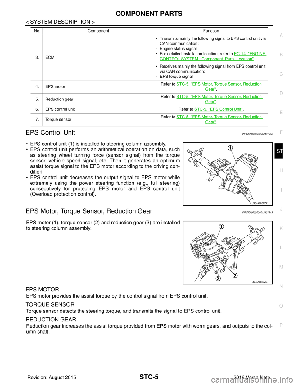
• EPS control unit (1) is installed to steering column assembly.
• EPS control unit performs an arithmetical operation on data, such as steering wheel turning force (sensor signal) from the torque
sensor, vehicle speed signal, etc. Then it generates an optimum
assist torque signal to the EPS motor according to the driving con-
dition.
• EPS control unit decreases the output signal to EPS motor while
extremely using the power steering function (e.g., full steering)
consecutively for protecting EPS motor and EPS control unit
(Overload protection control).
EPS Motor, Torque Sensor, Reduction GearINFOID:0000000012431943
EPS motor (1), torque sensor (2) and reduction gear (3) are installed
to steering column assembly.
EPS MOTOR
EPS motor provides the assist torque by the control signal from EPS control unit.
TORQUE SENSOR
Torque sensor detects the steering torque, and transmits the signal to EPS control unit.
REDUCTION GEAR
Reduction gear increases the assist torque provided from EPS motor with worm gears, and outputs to the col-
umn shaft.
3. ECM • Transmits mainly th
e following signal to EPS control unit via
CAN communication:
- Engine status signal
• For detailed installation location, refer to EC-14, "ENGINE
CONTROL SYSTEM : ComponentPartsLocation".
• Receives mainly the following signal from EPS control unit
via CAN communication:
- EPS torque signal
4. EPS motor Refer to STC-5, "
EPS Motor, Torque Sensor, Reduction
Gear".
5. Reduction gear Refer to STC-5, "
EPS Motor, Torque Sensor, Reduction
Gear".
6. EPS control unit Refer to STC-5, "
EPS Control Unit".
7. Torque sensor Refer to STC-5, "
EPS Motor, Torque Sensor, Reduction
Gear".
No.
Component Function
JSGIA0852ZZ
JSGIA0853ZZ
Revision: August 2015 2016 Versa Note
cardiagn.com
Page 3190 of 3641

STC-6
< SYSTEM DESCRIPTION >
DIAGNOSIS SYSTEM (EPS CONTROL UNIT)
DIAGNOSIS SYSTEM (EPS CONTROL UNIT)
CONSULT FunctionINFOID:0000000012431944
FUNCTION
CONSULT can display each diagnostic item usi ng the diagnostic test modes shown following:
*: The following diagnosis information is cleared by erasing:
•DTC
• Freeze frame data (FFD)
ECU IDENTIFICATION
Displays the part number stored in the control unit.
SELF DIAGNOSTIC RESULT MODE
Refer to STC-10, "DTC Index".
When “CRNT” is displayed on “Self Diagnostic Result”.
• The system is presently malfunctioning.
When “PAST” is displayed on “Self Diagnostic Result”.• System malfunction in the past is detect ed, but the system is presently normal.
FREEZE FRAME DATA (FFD)
The following vehicle status is recorded when DTC is detected and is displayed on CONSULT:
DATA MONITOR MODE
*1: Almost in accordance with the value of “MOTOR S IG”. It is not a malfunction though these values are not
accorded when steering quickly.
Diagnostic test mode Function
ECU Identification The part number stored in the control unit can be read.
Self Diagnostic Result Self-diagnostic results and freeze frame data can be read and erased quickly.
*
Data MonitorInput/Output data in the EPS control unit can be read.
Item name Display item
IGN COUNTER
(0-39) The number of times that ignition switch is tu
rned ON after the DTC is detected is displayed.
• When “0” is displayed: It indicates that the system is presently malfunctioning.
• When except “0” is displayed: It indicates that system malfunction in the past is detected, but the system is pres-
ently normal.
NOTE:
Each time when ignition switch is turned OFF to ON, numerical number increases in 1 →2→3...38 →39.
When the operation number of times exceeds 39, the number does not increase and “39” is displayed until self-
diagnosis is erased.
Monitor item (Unit) Remarks
BATTERY VOLT (V) Displays the power supply voltage for EPS control unit.
TORQUE SENSOR (Nm) Displays steering wheel turning force detected by torque sensor.
MOTOR CURRENT (A) Displays the current value consumed by EPS motor.
*1
MOTOR SIG (A) Displays the current commanded value to EPS motor.
ASSIST TORQUE (Nm) Displays assist torque being output by the electric power steering.
C/U TEMP ( °C or °F) Displays the temperature of the EPS control unit.
ASSIST LEVEL (%) Normally displays 100%. In case of an excessive stationary steering, the assist
curvature gradually falls. However, it return to 100% when left standing.
*2
VEHICLE SPEED (km/h or MPH)
Vehicle speed is displayed from vehicle speed signal via CAN communication.*3
WARNING LAMP (On/Off)EPS warning lamp control status is displayed.
ENGINE STATUS (Stop/Run) Engine speed is displayed from engine status signal via CAN communication.
Revision: August 2015 2016 Versa Note
cardiagn.com
Page 3192 of 3641

STC-8
< ECU DIAGNOSIS INFORMATION >
EPS CONTROL UNIT
ECU DIAGNOSIS INFORMATION
EPS CONTROL UNIT
Reference ValueINFOID:0000000012431945
VALUES ON THE DIAGNOSIS TOOL
CAUTION:
The output signal indicates the EPS control unit calculation data. The normal values will be displayed
even in the event that the output circuit (harness) is open.
*1: Almost in accordance with the value of “MOTOR S IG”. It is not a malfunction though these values are not
accorded when steering quickly.
*2: A fixed value is indicated regardless of steering turning.
*3: Normally displays 100%. In case of an excessive stat ionary steering, the assist curvature gradually falls.
However, it returns to 100% when left standing.
*4: It is not a malfunction, though it might not be co rresponding just after ignition switch in turned ON.
Monitor item Data monitor
Condition Display value
BATTERY VOLT Ignition switch: ON Battery voltage
TORQUE SENSOR Engine running Steering wheel: Not
steering (There is
no steering force) Approx. 0 Nm
Steering wheel: Right turn Positive value (Nm)
Steering wheel: Left turn Negative value (Nm)
MOTOR CURRENT Engine running Steering wheel: Not
steering (There is
no steering force) Approx. 0 A
Steering wheel: Right or left turn Displays consumption current of
EPS motor (A)
*1
MOTOR SIG
Engine runningSteering wheel: Not
steering (There is
no steering force) Approx. 0 A
Steering wheel: Right turn Positive value (A)
Steering wheel: Left turn Negative value (A)
ASSIST TORQUE Engine running Approx. 0 Nm
*2
C/U TEMPIgnition switch ON or engine running Displays temperature of inside of
EPS control unit (
°C or °F)
ASSIST LEVEL Engine running
100 %
*3
VEHICLE SPEEDVehicle stopped
0 km/h or mph
While driving Approximately equal to the indication
on speedometer*4
(inside of ±
10%)
WARNING LAMP EPS warning lamp: ON
On
EPS warning lamp: OFF Off
ENGINE STATUS Engine not running
Stop
Engine running Run
Revision: August 2015 2016 Versa Note
cardiagn.com
Page 3193 of 3641

EPS CONTROL UNITSTC-9
< ECU DIAGNOSIS INFORMATION >
C
DE
F
H I
J
K L
M A
B
STC
N
O P
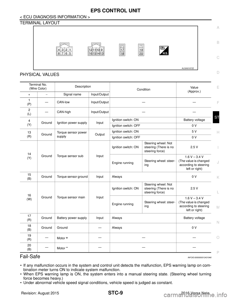
TERMINAL LAYOUT
PHYSICAL VALUES
Fail-SafeINFOID:0000000012431946
• If any malfunction occurs in the system and control uni t detects the malfunction, EPS warning lamp on com-
bination meter turns ON to indicate system malfunction.
• When EPS warning lamp is ON, the system enters into a manual steering state. (Steering wheel turning force becomes heavy.)
• Under abnormal vehicle speed signal conditions, vehicle speed is judged as constant.
ALGIA0167ZZ
Te r m i n a l N o .
(Wire Color) Description
ConditionVa l u e
(Approx.)
+ − Signal name Input/Output
1
(P) — CAN-low
Input/Output ——
2
(L) — CAN-high
Input/Output ——
4
(Y) Ground Ignition power supply Input Ignition switch: ON
Battery voltage
Ignition switch: OFF 0 V
13
(R) Ground Torque sensor power
supply
OutputIgnition switch: ON
5 V
Ignition switch: OFF 0 V
14
(Y) Ground Torque sensor sub Input Ignition switch: ON
Steering wheel: Not
steering (There is no
steering force) 2.5 V
Engine running Steering wheel: steer-
ing 1.6 V – 3.4 V
(The value is changed according to steering
left or right)
15
(B) Ground Torque sensor ground Input Always
0 V
16
(W) Ground Torque sensor main Input Ignition switch: ON
Steering wheel: Not
steering (There is no
steering force) 2.5 V
Engine running Steering wheel: steer-
ing 1.6 V – 3.4 V
(The value is changed according to steering left or right)
17
(R) Ground Battery power supply Input Always
Battery voltage
18
(B) Ground Ground
— Always 0 V
19
(R) —
Motor —— —
20
(B) —
Motor —— —
Revision: August 2015
2016 Versa Note
cardiagn.com
Page 3194 of 3641

STC-10
< ECU DIAGNOSIS INFORMATION >
EPS CONTROL UNIT
Protection Function
INFOID:0000000012431947
EPS control unit decreases the output signal to EPS mo tor while extremely using the power steering function
(e.g., full steering) consecutively for protecting EPS motor and EPS control unit (Overload protection control).
While activating overload protection control, the assist torque gradually decreases, and the steering wheel
turning force becomes heavy. The normal assist torque reactivates by no steering.
DTC Inspection Priority ChartINFOID:0000000012431948
When multiple DTCs are detected simultaneously, c heck one by one depending on the following priority list:
DTC IndexINFOID:0000000012431949
Priority Priority order item (DTC)
1 U1000 CAN COMM CIRCUIT
2 C1609 CAN VHCL SPEED, C1610 CAN ENG RPM
3 C1601 BATTERY VOLT
4 Other than the above
DTC Items (CONSULT screen terms) Reference
C1601 BATTERY VOLT STC-18, "
DTC Logic"
C1604TORQUE SENSOR STC-21, "DTC Logic"
C1606EPS MOTOR STC-23, "DTC Logic"
C1607EEPROM STC-25, "DTC Logic"
C1608CONTROL UNIT STC-25, "DTC Logic"
C1609CAN VHCL SPEED STC-26, "DTC Logic"
C1610CAN ENG RPM STC-27, "DTC Logic"
U1000CAN COMM CIRCUIT STC-28, "DTC Logic"
Revision: August 2015 2016 Versa Note
cardiagn.com
Page 3205 of 3641

C1604 TORQUE SENSORSTC-21
< DTC/CIRCUIT DIAGNOSIS >
C
DE
F
H I
J
K L
M A
B
STC
N
O P
C1604 TORQUE SENSOR
DTC LogicINFOID:0000000012431955
DTC DETECTION LOGIC
DTC CONFIRMATION PROCEDURE
1.PRECONDITIONING
If “DTC CONFIRMATION PROCEDURE” has been previously conducted, always turn ignition switch OFF and
wait at least 10 seconds before conducting the next test.
>> GO TO 2.
2.DTC REPRODUCTION PROCEDURE
With CONSULT
1. Turn the ignition switch OFF to ON.
2. Perform “Self Diagnostic Result” of “EPS”.
Is DTC
“C1604” detected?
YES >> Proceed to diagnosis procedure. Refer to STC-21, "Diagnosis Procedure".
NO >> Inspection End.
Diagnosis ProcedureINFOID:0000000012431956
Regarding Wiring Diagram information, refer to STC-11, "Wiring Diagram".
1.CHECK TORQUE SENSOR POWER SUPPLY CIRCUIT
1. Turn ignition switch OFF to ON. CAUTION:
Never start the engine.
2. Check voltage between EPS control unit harness connector terminal and ground.
CAUTION:
Steering wheel in neutral position . (There is no steering force.)
Is the inspection result normal?
YES >> GO TO 2.
NO >> Perform the trouble diagnosis for battery power supply circuit. Refer to STC-18, "
Diagnosis Proce-
dure".
2.CHECK TORQUE SENSOR GROUND CIRCUIT
1. Turn ignition switch OFF.
2. Check continuity between EPS control unit harness connector terminal and ground. CAUTION:
Steering wheel in neutral position . (There is no steering force.)
DTCDisplay item Malfunction detected condition Possible cause
C1604 TORQUE SENSOR When torque sensor output signal is malfunctioning. • Harness or connector
• Torque sensor
• EPS control unit
EPS control unit
—Vo l ta g e
(Approx.)
Connector Terminal
M54 13Ground 5 V
Revision: August 2015 2016 Versa Note
cardiagn.com