2016 NISSAN NOTE wheel torque
[x] Cancel search: wheel torquePage 1856 of 3641
TRANSVERSE LINKFSU-11
< REMOVAL AND INSTALLATION >
C
DF
G H
I
J
K L
M A
B
FSU
N
O P
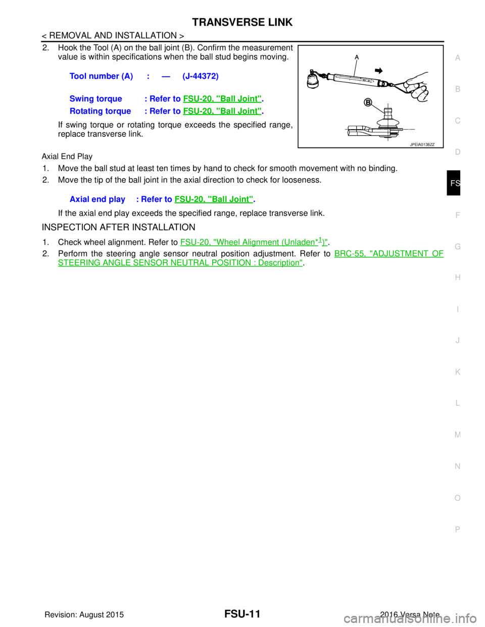
2. Hook the Tool (A) on the ball joint (B). Confirm the measurement value is within specifications when the ball stud begins moving.
If swing torque or rotating torque exceeds the specified range,
replace transverse link.
Axial End Play
1. Move the ball stud at least ten times by hand to check for smooth movement with no binding.
2. Move the tip of the ball joint in the axial direction to check for looseness.
If the axial end play exceeds the specified range, replace transverse link.
INSPECTION AFTER INSTALLATION
1. Check wheel alignment. Refer to FSU-20, "Wheel Alignment (Unladen*1)".
2. Perform the steering angle sensor neutral position adjustment. Refer to BRC-55, "
ADJUSTMENT OF
STEERING ANGLE SENSOR NEUTRAL POSITION : Description".
Tool number (A) : — (J-44372)
Swing torque : Refer to
FSU-20, "
Ball Joint".
Rotating torque : Refer to FSU-20, "
Ball Joint".
JPEIA0138ZZ
Axial end play : Refer to FSU-20, "Ball Joint".
Revision: August 2015 2016 Versa Note
cardiagn.com
Page 1858 of 3641
FRONT STABILIZERFSU-13
< REMOVAL AND INSTALLATION >
C
DF
G H
I
J
K L
M A
B
FSU
N
O P
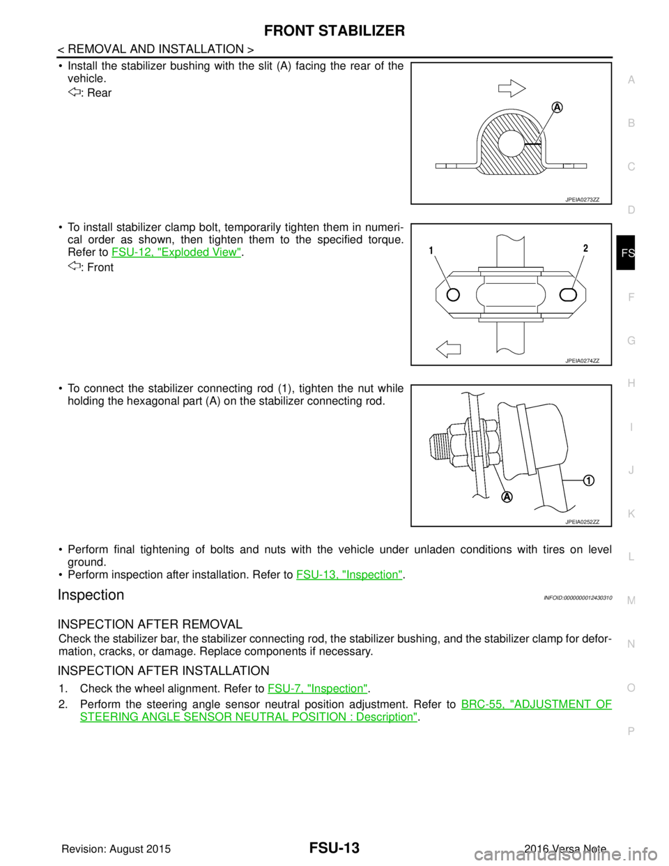
• Install the stabilizer bushing with the slit (A) facing the rear of the vehicle.
: Rear
• To install stabilizer clamp bolt, temporarily tighten them in numeri- cal order as shown, then tighten them to the specified torque.
Refer to FSU-12, "
Exploded View".
: Front
• To connect the stabilizer connecting rod (1), tighten the nut while holding the hexagonal part (A) on the stabilizer connecting rod.
• Perform final tightening of bolts and nuts with the vehicle under unladen conditions with tires on level ground.
• Perform inspection after installation. Refer to FSU-13, "
Inspection".
InspectionINFOID:0000000012430310
INSPECTION AFTER REMOVAL
Check the stabilizer bar, the stabilizer connecting rod, t he stabilizer bushing, and the stabilizer clamp for defor-
mation, cracks, or damage. Replace components if necessary.
INSPECTION AFTER INSTALLATION
1. Check the wheel alignment. Refer to FSU-7, "Inspection".
2. Perform the steering angle sensor neutral position adjustment. Refer to BRC-55, "
ADJUSTMENT OF
STEERING ANGLE SENSOR NEUTRAL POSITION : Description".
JPEIA0273ZZ
JPEIA0274ZZ
JPEIA0252ZZ
Revision: August 2015 2016 Versa Note
cardiagn.com
Page 1859 of 3641
FSU-14
< UNIT REMOVAL AND INSTALLATION >
FRONT SUSPENSION MEMBER
UNIT REMOVAL AND INSTALLATION
FRONT SUSPENSION MEMBER
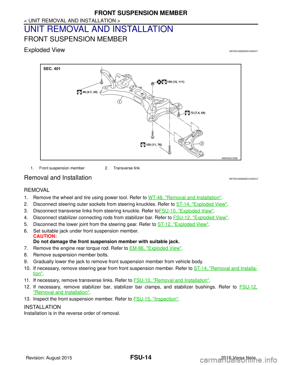
Exploded ViewINFOID:0000000012430311
Removal and InstallationINFOID:0000000012430312
REMOVAL
1. Remove the wheel and tire using power tool. Refer to WT-48, "Removal and Installation".
2. Disconnect steering outer sockets from steering knuckles. Refer to ST-14, "
Exploded View".
3. Disconnect transverse links from steering knuckle. Refer to FSU-10, "
Exploded View".
4. Disconnect stabilizer connecting rods from stabilizer bar. Refer to FSU-12, "
Exploded View".
5. Disconnect the lower joint from the steering gear. Refer to ST-12, "
Exploded View".
6. Set suitable jack under front suspension member. CAUTION:
Do not damage the front suspensi on member with suitable jack.
7. Remove the engine rear torque rod. Refer to EM-86, "
Exploded View".
8. Remove suspension member bolts.
9. Gradually lower the jack to remove front suspension member from vehicle body.
10. If necessary, remove steering gear from front suspension member. Refer to ST-14, "
Removal and Installa-
tion".
11. If necessary, remove transverse links. Refer to FSU-10, "
Removal and Installation".
12. If necessary, remove stabilizer bar, stabilizer bar clamps, and stabilizer bushings. Refer to FSU-12,
"Removal and Installation".
13. Inspect the front suspension member. Refer to FSU-15, "
Inspection".
INSTALLATION
Installation is in the reverse order of removal.
1. Front suspension member2. Transverse link
AWEIA0210GB
Revision: August 2015 2016 Versa Note
cardiagn.com
Page 1865 of 3641
FSU-20
< SERVICE DATA AND SPECIFICATIONS (SDS)
SERVICE DATA AND SPECIFICATIONS (SDS)
SERVICE DATA AND SPECIFICATIONS (SDS)
SERVICE DATA AND SPECIFICATIONS (SDS)
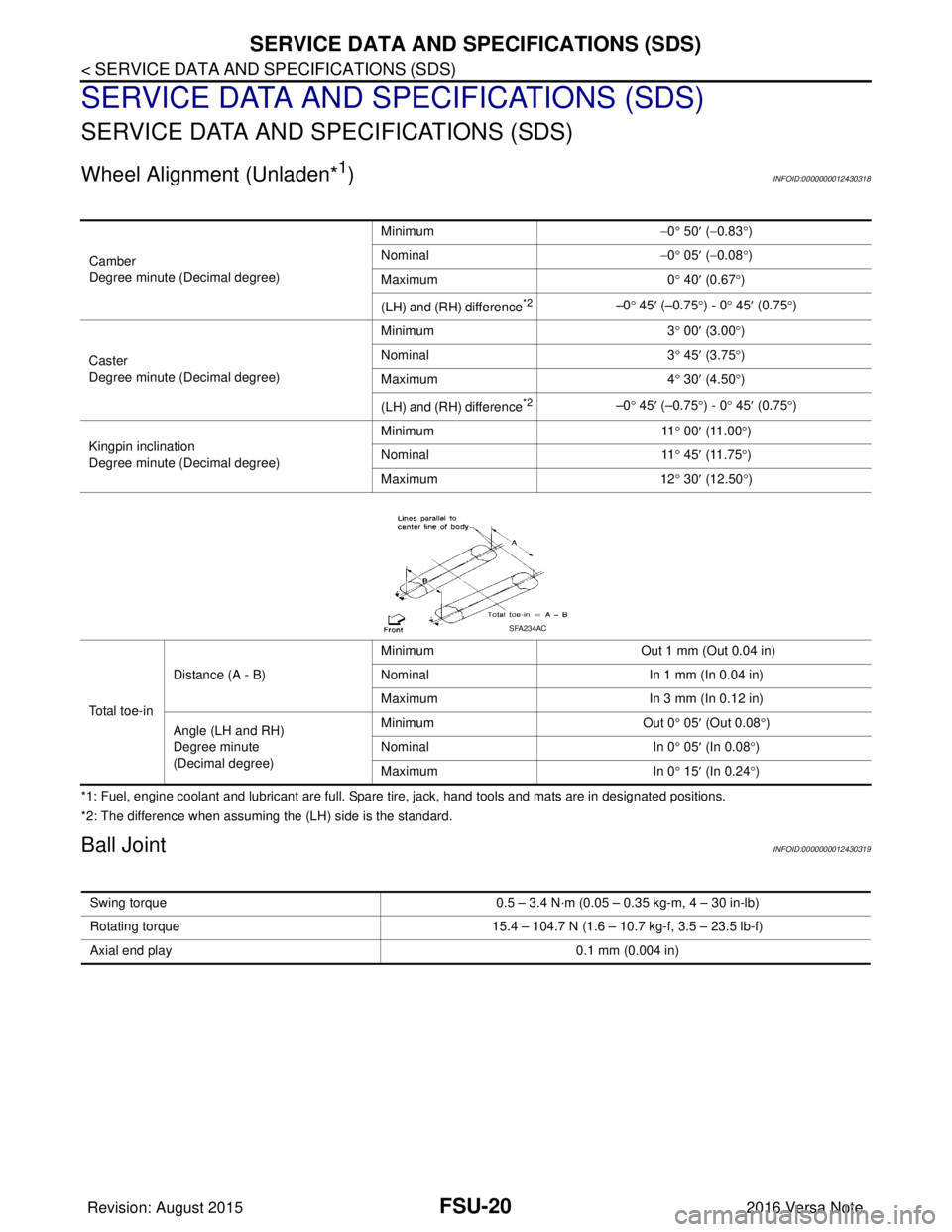
Wheel Alignment (Unladen*1)INFOID:0000000012430318
*1: Fuel, engine coolant and lubricant are full. Spare tire, jack, hand tools and mats are in designated positions.
*2: The difference when assuming the (LH) side is the standard.
Ball JointINFOID:0000000012430319
Camber
Degree minute (Decimal degree)Minimum
−0 ° 50 ′ ( −0.83 °)
Nominal −0 ° 05 ′ ( −0.08 °)
Maximum 0° 40 ′ (0.67 °)
(LH) and (RH) difference
*2–0 ° 45 ′ (–0.75 °) - 0 ° 45 ′ (0.75 °)
Caster
Degree minute (Decimal degree) Minimum
3° 00 ′ (3.00 °)
Nominal 3° 45 ′ (3.75 °)
Maximum 4° 30 ′ (4.50 °)
(LH) and (RH) difference
*2–0 ° 45 ′ (–0.75 °) - 0 ° 45 ′ (0.75 °)
Kingpin inclination
Degree minute (Decimal degree) Minimum
11° 00 ′ (11.00 °)
Nominal 11° 45 ′ (11.75 °)
Maximum 12° 30 ′ (12.50 °)
To t a l t o e - i n Distance (A - B)
Minimum
Out 1 mm (Out 0.04 in)
Nominal In 1 mm (In 0.04 in)
Maximum In 3 mm (In 0.12 in)
Angle (LH and RH)
Degree minute
(Decimal degree) Minimum
Out 0° 05′ (Out 0.08 °)
Nominal In 0° 05 ′ (In 0.08 °)
Maximum In 0° 15′ (In 0.24 °)
SFA234AC
Swing torque 0.5 – 3.4 N·m (0.05 – 0.35 kg-m, 4 – 30 in-lb)
Rotating torque 15.4 – 104.7 N (1.6 – 10.7 kg-f, 3.5 – 23.5 lb-f)
Axial end play 0.1 mm (0.004 in)
Revision: August 2015 2016 Versa Note
cardiagn.com
Page 1889 of 3641

GI-1
GENERAL INFORMATION
C
DE
F
G H
I
J
K L
M B
GI
SECTION GI
N
O P
CONTENTS
GENERAL INFORMATION
HOW TO USE THIS MANU AL ......................3
HOW TO USE THIS MANUAL ....................... .....3
Description .......................................................... ......3
Terms ........................................................................3
Units ..........................................................................3
Contents ....................................................................3
Relation between Illustrations and Descriptions .......4
Components ..............................................................4
HOW TO FOLLOW TROUBLE DIAGNOSES .....6
Description ................................................................6
How to Follow Test Groups in Trouble Diagnosis ......6
Key to Symbols Signifying Measurements or Pro-
cedures ............................................................... ......
7
HOW TO READ WIRING DIAGRAMS ................9
Connector Symbols ............................................. ......9
Sample/Wiring Diagram -Example- .........................10
Connector Information .............................................12
ABBREVIATIONS .......................................... ....14
Abbreviation List .................................................. ....14
TIGHTENING TORQUE OF STANDARD
BOLTS ................................................................
19
Description .......................................................... ....19
Tightening Torque Table (New Standard Includ-
ed) ...........................................................................
19
RECOMMENDED CHEMICAL PRODUCTS
AND SEALANTS ................................................
22
Recommended Chemical Products and Sealants ....22
PRECAUTION ..............................................23
PRECAUTIONS .............................................. ....23
Description .......................................................... ....23
Precaution for Supplemental Restraint System
(SRS) "AIR BAG" and "SEAT BELT PRE-TEN-
SIONER" .................................................................
23
Procedures without Cowl Top Cover .......................23
Cautions in Removing Battery Terminal and AV
Control Unit (Models with AV Control Unit) .............
23
General Precautions ............................................ ....24
Three Way Catalyst .................................................25
Fuel ..........................................................................25
Multiport Fuel Injection System or Engine Control
System .....................................................................
26
Hoses ......................................................................26
Engine Oils ..............................................................27
Air Conditioning .......................................................27
LIFTING POINT .................................................28
Special Service Tool ................................................28
Garage Jack and Safety Stand ................................28
2-Pole Lift ................................................................29
Board-on Lift ............................................................30
TOW TRUCK TOWING .....................................31
Tow Truck Towing ...................................................31
Vehicle Recovery (Freeing a Stuck Vehicle) ...........31
VEHICLE INFORMATION ...........................33
IDENTIFICATION INFORMATION ....................33
Model Variation .................................................... ....33
Identification Number ...............................................34
Identification Plate ...................................................35
Engine Serial Number .............................................36
CVT Number ............................................................36
Manual Transaxle Number ......................................36
Dimensions ..............................................................36
Wheels & Tires ........................................................37
BASIC INSPECTION ...................................38
SERVICE INFORMATION FOR ELECTRICAL
INCIDENT ..........................................................
38
Work Flow ............................................................ ....38
Control Units and Electrical Parts ............................38
How to Check Terminal ...........................................39
Intermittent Incident ............................................. ....42
Circuit Inspection .....................................................44
Revision: August 2015 2016 Versa Note
cardiagn.com
Page 2328 of 3641
ENGINE MAINTENANCEMA-13
< PERIODIC MAINTENANCE >
C
DE
F
G H
I
J
K L
M B
MA
N
O A
ENGINE MAINTENANCE
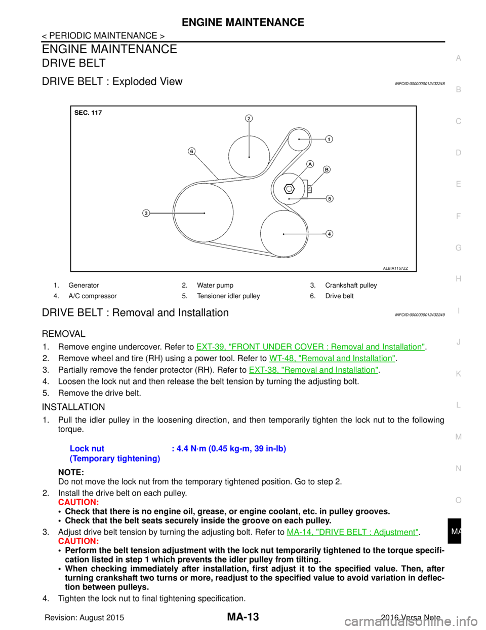
DRIVE BELT
DRIVE BELT : Exploded ViewINFOID:0000000012432248
DRIVE BELT : Removal and InstallationINFOID:0000000012432249
REMOVAL
1. Remove engine undercover. Refer to
EXT-39, "FRONT UNDER COVER : Removal and Installation".
2. Remove wheel and tire (RH) using a power tool. Refer to WT-48, "
Removal and Installation".
3. Partially remove the fender protector (RH). Refer to EXT-38, "
Removal and Installation".
4. Loosen the lock nut and then release the belt tension by turning the adjusting bolt.
5. Remove the drive belt.
INSTALLATION
1. Pull the idler pulley in the loosening direction, and then temporarily tighten the lock nut to the following
torque.
NOTE:
Do not move the lock nut from the temporary tightened position. Go to step 2.
2. Install the drive belt on each pulley. CAUTION:
• Check that there is no engine oil, grease, or engine coolant, etc. in pulley grooves.
• Check that the belt seats securely inside the groove on each pulley.
3. Adjust drive belt tension by turning the adjusting bolt. Refer to MA-14, "
DRIVE BELT : Adjustment".
CAUTION:
• Perform the belt tension adjustment with the lock nut temporarily tightened to the torque specifi-
cation listed in step 1 which preven ts the idler pulley from tilting.
• When checking immediately after in stallation, first adjust it to the specified value. Then, after
turning crankshaft two turns or more, readjust to the specified value to avoid variation in deflec-
tion between pulleys.
4. Tighten the lock nut to final tightening specification.
1. Generator 2. Water pump3. Crankshaft pulley
4. A/C compressor 5. Tensioner idler pulley6. Drive belt
ALBIA1157ZZ
Lock nut
(Temporary tightening): 4.4 N·m (0.45 kg-m, 39 in-lb)
Revision: August 2015
2016 Versa Note
cardiagn.com
Page 2347 of 3641
MA-32
< PERIODIC MAINTENANCE >
CHASSIS AND BODY MAINTENANCE
GEAR OIL : Refilling
INFOID:0000000012432275
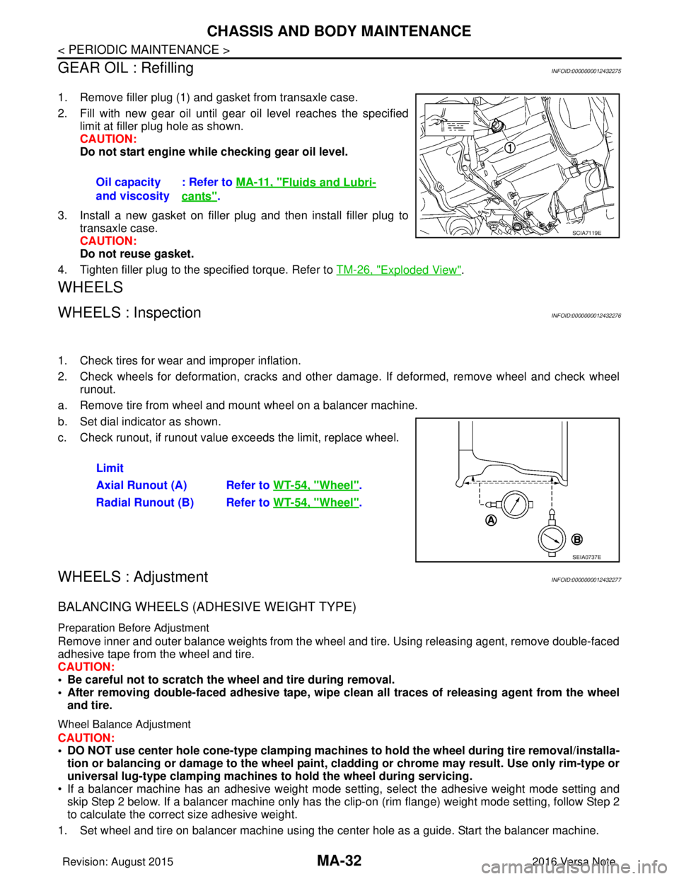
1. Remove filler plug (1) and gasket from transaxle case.
2. Fill with new gear oil until gear oil level reaches the specified limit at filler plug hole as shown.
CAUTION:
Do not start engine whil e checking gear oil level.
3. Install a new gasket on filler plug and then install filler plug to transaxle case.
CAUTION:
Do not reuse gasket.
4. Tighten filler plug to the specified torque. Refer to TM-26, "
Exploded View".
WHEELS
WHEELS : InspectionINFOID:0000000012432276
1. Check tires for wear and improper inflation.
2. Check wheels for deformation, cracks and other dam age. If deformed, remove wheel and check wheel
runout.
a. Remove tire from wheel and mount wheel on a balancer machine.
b. Set dial indicator as shown.
c. Check runout, if runout value exceeds the limit, replace wheel.
WHEELS : AdjustmentINFOID:0000000012432277
BALANCING WHEELS (ADHESIVE WEIGHT TYPE)
Preparation Before Adjustment
Remove inner and outer balance weights from the wheel and tire. Using releasing agent, remove double-faced
adhesive tape from the wheel and tire.
CAUTION:
• Be careful not to scratch the wheel and tire during removal.
• After removing double-faced adh esive tape, wipe clean all traces of releasing agent from the wheel
and tire.
Wheel Balance Adjustment
CAUTION:
• DO NOT use center hole cone-type clamping machines to hold the wheel during tire removal/installa-
tion or balancing or damage to the wheel paint, cladding or chrome may result. Use only rim-type or
universal lug-type clamping machines to hold the wheel during servicing.
• If a balancer machine has an adhesive weight mode se tting, select the adhesive weight mode setting and
skip Step 2 below. If a balancer machine only has the clip -on (rim flange) weight mode setting, follow Step 2
to calculate the correct size adhesive weight.
1. Set wheel and tire on balancer machine using the center hole as a guide. Start the balancer machine. Oil capacity
and viscosity
: Refer to
MA-11, "
Fluids and Lubri-
cants".
SCIA7119E
Limit
Axial Runout (A) Refer to WT-54, "
Wheel".
Radial Runout (B) Refer to WT-54, "
Wheel".
SEIA0737E
Revision: August 2015 2016 Versa Note
cardiagn.com
Page 2349 of 3641
MA-34
< PERIODIC MAINTENANCE >
CHASSIS AND BODY MAINTENANCE
TIRE ROTATION
• Follow the maintenance schedule for tire rotation service intervals.Refer to MA-7, "
Introduction of Periodic Maintenance".
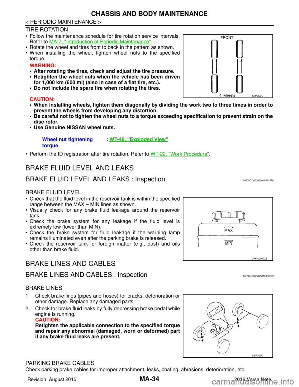
• Rotate the wheel and tires front to back in the pattern as shown.
• When installing the wheel, tighten wheel nuts to the specified torque.
WARNING:
• After rotating the tires, check and adjust the tire pressure.
• Retighten the wheel nuts when the vehicle has been driven
for 1,000 km (600 mi) (also in case of a flat tire, etc.).
• Do not include the spare tire when rotating the tires.
CAUTION:
• When installing wheels, ti ghten them diagonally by dividing the work two to three times in order to
prevent the wheels from d eveloping any distortion.
• Be careful not to tighten the wh eel nuts to a torque exceeding speci fication to prevent strain on the
disc rotor.
• Use Genuine NISSAN wheel nuts.
• Perform the ID registration after tire rotation. Refer to WT-22, "
Work Procedure".
BRAKE FLUID LEVEL AND LEAKS
BRAKE FLUID LEVEL AND LEAKS : InspectionINFOID:0000000012432278
BRAKE FLUID LEVEL
• Check that the fluid level in the reservoir tank is within the specified
range between the MAX – MIN lines as shown.
• Visually check for any brake fluid leakage around the reservoir tank.
• Check the brake system for any leakage if the fluid level is extremely low (lower than MIN).
• Check the brake system for fluid leakage if the warning lamp
remains illuminated even after the parking brake is released.
• Check the reservoir tank for foreign matter (e.g., dust) and oils other than brake fluid.
BRAKE LINES AND CABLES
BRAKE LINES AND CABLES : InspectionINFOID:0000000012432279
BRAKE LINES
1. Check brake lines (pipes and hoses) for cracks, deterioration or other damage. Replace any damaged parts.
2. Check for brake fluid leaks by fully depressing brake pedal while engine is running.
CAUTION:
Retighten the applicable conn ection to the specified torque
and repair any abnormal (damag ed, worn or deformed) part
if any brake fluid leaks are present.
PARKING BRAKE CABLES
Check parking brake cables for improper attachment , leaks, chafing, abrasions, deterioration, etc.
Wheel nut tightening
torque
:
WT-48, "
Exploded View"
SMA829C
JPFIA0007ZZ
SBR389C
Revision: August 2015 2016 Versa Note
cardiagn.com