2016 NISSAN NOTE wheel bolts
[x] Cancel search: wheel boltsPage 2721 of 3641
PREPARATIONRAX-3
< PREPARATION >
CEF
G H
I
J
K L
M A
B
RAX
N
O P
PREPARATION
PREPARATION
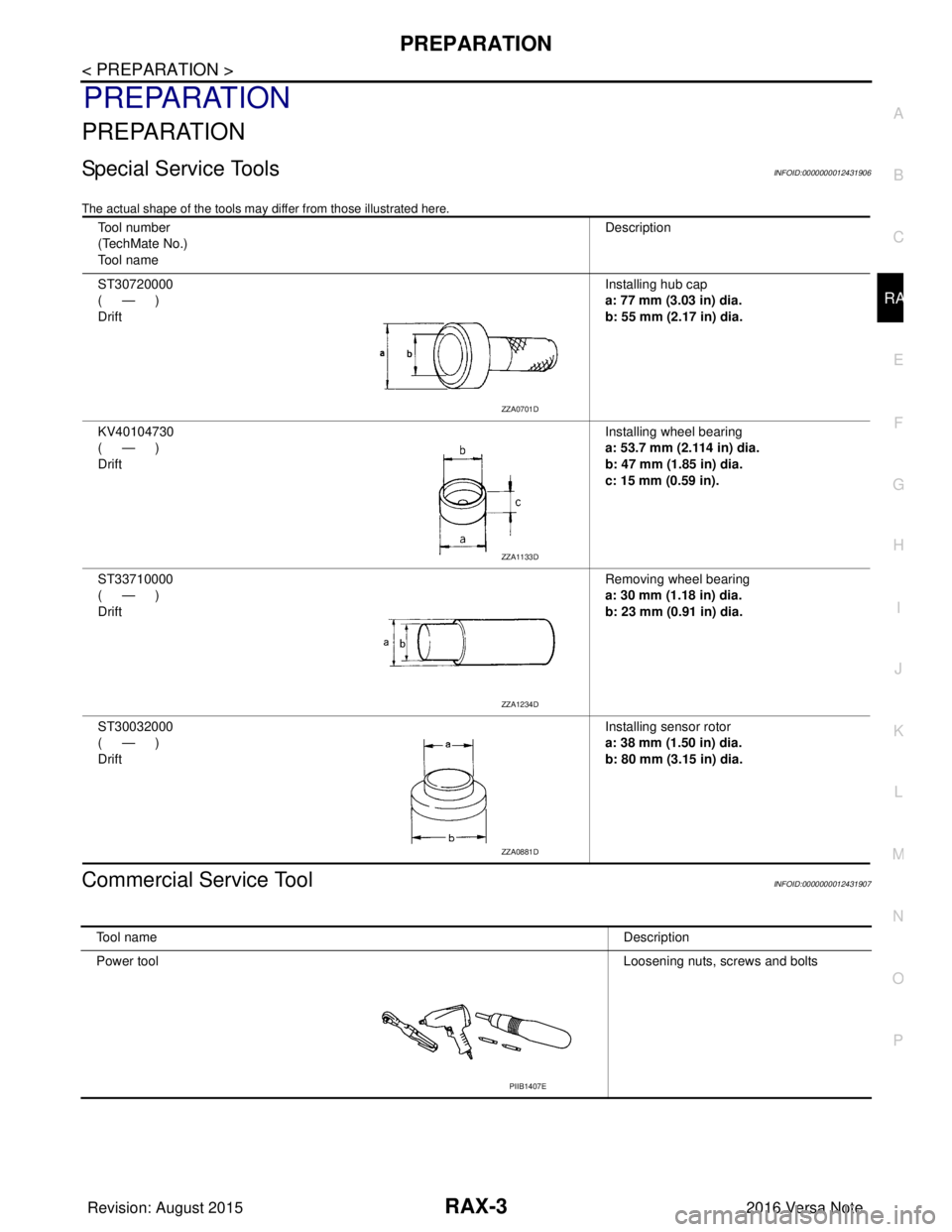
Special Service ToolsINFOID:0000000012431906
The actual shape of the tools may di ffer from those illustrated here.
Commercial Service ToolINFOID:0000000012431907
Tool number
(TechMate No.)
Tool name Description
ST30720000
(—)
Drift Installing hub cap
a: 77 mm (3.03 in) dia.
b: 55 mm (2.17 in) dia.
KV40104730
(—)
Drift Installing wheel bearing
a: 53.7 mm (2.114 in) dia.
b: 47 mm (1.85 in) dia.
c: 15 mm (0.59 in).
ST33710000
(—)
Drift Removing wheel bearing
a: 30 mm (1.18 in) dia.
b: 23 mm (0.91 in) dia.
ST30032000
(—)
Drift Installing sensor rotor
a: 38 mm (1.50 in) dia.
b: 80 mm (3.15 in) dia.
ZZA0701D
ZZA1133D
ZZA1234D
ZZA0881D
Tool name
Description
Power tool Loosening nuts, screws and bolts
PIIB1407E
Revision: August 2015 2016 Versa Note
cardiagn.com
Page 2724 of 3641
RAX-6
< REMOVAL AND INSTALLATION >
REAR WHEEL HUB
REMOVAL AND INSTALLATION
REAR WHEEL HUB
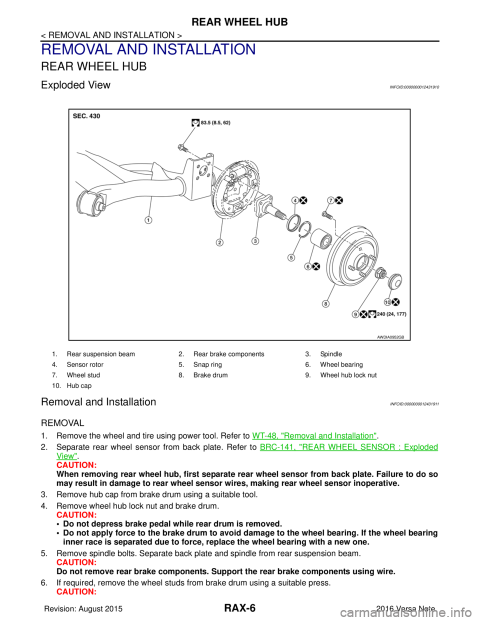
Exploded ViewINFOID:0000000012431910
Removal and InstallationINFOID:0000000012431911
REMOVAL
1. Remove the wheel and tire using power tool. Refer to WT-48, "Removal and Installation".
2. Separate rear wheel sensor from back plate. Refer to BRC-141, "
REAR WHEEL SENSOR : Exploded
View".
CAUTION:
When removing rear wheel hub, first separate rear wheel sensor from back plate. Failure to do so
may result in damage to rear wheel senso r wires, making rear wheel sensor inoperative.
3. Remove hub cap from brake drum using a suitable tool.
4. Remove wheel hub lock nut and brake drum. CAUTION:
• Do not depress brake pedal while rear drum is removed.
• Do not apply force to the brake drum to avoid dama ge to the wheel bearing. If the wheel bearing
inner race is separated due to force, replace the wheel bearing with a new one.
5. Remove spindle bolts. Separate back plate and spindle from rear suspension beam. CAUTION:
Do not remove rear brake comp onents. Support the rear brake components using wire.
6. If required, remove the wheel studs from brake drum using a suitable press.
CAUTION:
1. Rear suspension beam 2. Rear brake components 3. Spindle
4. Sensor rotor 5. Snap ring6. Wheel bearing
7. Wheel stud 8. Brake drum 9. Wheel hub lock nut
10. Hub cap
AWDIA0952GB
Revision: August 2015 2016 Versa Note
cardiagn.com
Page 2741 of 3641
REAR SUSPENSION BEAMRSU-13
< REMOVAL AND INSTALLATION >
C
DF
G H
I
J
K L
M A
B
RSU
N
O P
REAR SUSPENSION BEAM
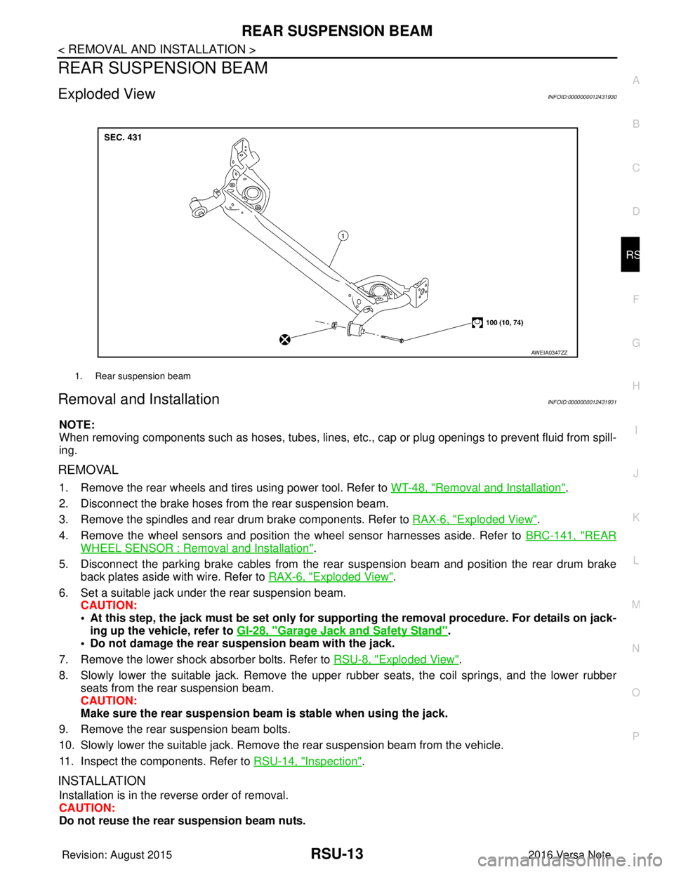
Exploded ViewINFOID:0000000012431930
Removal and InstallationINFOID:0000000012431931
NOTE:
When removing components such as hoses, tubes, lines, etc. , cap or plug openings to prevent fluid from spill-
ing.
REMOVAL
1. Remove the rear wheels and tires using power tool. Refer to WT-48, "Removal and Installation".
2. Disconnect the brake hoses from the rear suspension beam.
3. Remove the spindles and rear drum brake components. Refer to RAX-6, "
Exploded View".
4. Remove the wheel sensors and position the wheel sensor harnesses aside. Refer to BRC-141, "
REAR
WHEEL SENSOR : Removal and Installation".
5. Disconnect the parking brake cables from the rear suspension beam and position the rear drum brake
back plates aside with wire. Refer to RAX-6, "
Exploded View".
6. Set a suitable jack under the rear suspension beam. CAUTION:
• At this step, the jack must be set only for suppo rting the removal procedure. For details on jack-
ing up the vehicle, refer to GI-28, "
Garage Jack and Safety Stand".
• Do not damage the rear su spension beam with the jack.
7. Remove the lower shock absorber bolts. Refer to RSU-8, "
Exploded View".
8. Slowly lower the suitable jack. Remove the upper rubber seats, the coil springs, and the lower rubber seats from the rear suspension beam.
CAUTION:
Make sure the rear susp ension beam is stable when using the jack.
9. Remove the rear suspension beam bolts.
10. Slowly lower the suitable jack. Remove the rear suspension beam from the vehicle.
11. Inspect the components. Refer to RSU-14, "
Inspection".
INSTALLATION
Installation is in the reverse order of removal.
CAUTION:
Do not reuse the rear suspension beam nuts.
1. Rear suspension beam
AWEIA0347ZZ
Revision: August 2015 2016 Versa Note
cardiagn.com
Page 2742 of 3641
RSU-14
< REMOVAL AND INSTALLATION >
REAR SUSPENSION BEAM
• Perform the final tightening of the rear suspension beam nuts and bolts under unladen conditions with thetires on level ground.
• Adjust the parking brake. Refer to PB-4, "
Inspection and Adjustment".
• Fill the hydraulic brake system. Refer to BR-12, "
Refilling".
• Bleed the hydraulic brake system. Refer to BR-13, "
Bleeding Brake System".
• Complete the inspection. Refer to BR-12, "
Inspection".
InspectionINFOID:0000000012431932
INSPECTION AFTER REMOVAL
Check the rear suspension beam for deformation, cracks or damage. Replace the parts if necessary.
INSPECTION AFTER INSTALLATION
1. Check the wheel sensor harness to be sure the connectors are fully seated.
2. Check the neutral position of the steering angle sensor. Refer to BRC-55, "
ADJUSTMENT OF STEERING
ANGLE SENSOR NEUTRAL POSITION : Description".
3. Check the wheel alignment. Refer to RSU-6, "
Inspection".
Revision: August 2015 2016 Versa Note
cardiagn.com
Page 3118 of 3641
SR-2
< PRECAUTION >
PRECAUTIONS
PRECAUTION
PRECAUTIONS
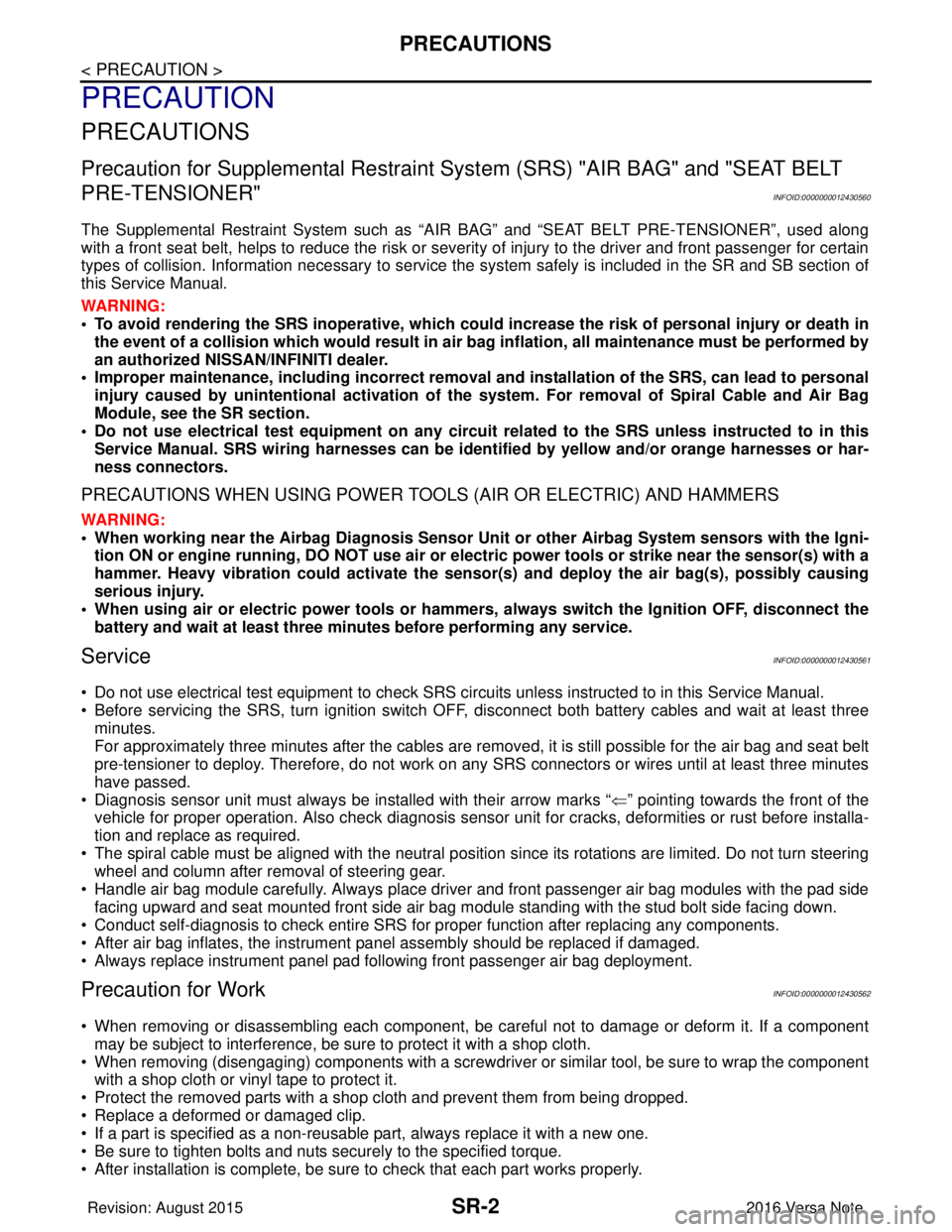
Precaution for Supplemental Restraint System (SRS) "AIR BAG" and "SEAT BELT
PRE-TENSIONER"
INFOID:0000000012430560
The Supplemental Restraint System such as “A IR BAG” and “SEAT BELT PRE-TENSIONER”, used along
with a front seat belt, helps to reduce the risk or severity of injury to the driver and front passenger for certain
types of collision. Information necessary to service the system safely is included in the SR and SB section of
this Service Manual.
WARNING:
• To avoid rendering the SRS inopera tive, which could increase the risk of personal injury or death in
the event of a collision which would result in air bag inflation, all maintenance must be performed by
an authorized NISSAN/INFINITI dealer.
• Improper maintenance, including in correct removal and installation of the SRS, can lead to personal
injury caused by unintent ional activation of the system. For re moval of Spiral Cable and Air Bag
Module, see the SR section.
• Do not use electrical test equipmen t on any circuit related to the SRS unless instructed to in this
Service Manual. SRS wiring harn esses can be identified by yellow and/or orange harnesses or har-
ness connectors.
PRECAUTIONS WHEN USING POWER TOOLS (AIR OR ELECTRIC) AND HAMMERS
WARNING:
• When working near the Airbag Diagnosis Sensor Unit or other Airbag System sensors with the Igni-
tion ON or engine running, DO NOT use air or electri c power tools or strike near the sensor(s) with a
hammer. Heavy vibration could activate the sensor( s) and deploy the air bag(s), possibly causing
serious injury.
• When using air or electric power tools or hammers , always switch the Ignition OFF, disconnect the
battery and wait at least three minutes before performing any service.
ServiceINFOID:0000000012430561
• Do not use electrical test equipment to check SRS ci rcuits unless instructed to in this Service Manual.
• Before servicing the SRS, turn ignition switch OFF, disconnect both battery cables and wait at least three
minutes.
For approximately three minutes after the cables are remo ved, it is still possible for the air bag and seat belt
pre-tensioner to deploy. Therefore, do not work on any SRS connectors or wires until at least three minutes
have passed.
• Diagnosis sensor unit must always be installed with their arrow marks “ ⇐” pointing towards the front of the
vehicle for proper operation. Also chec k diagnosis sensor unit for cracks, deformities or rust before installa-
tion and replace as required.
• The spiral cable must be aligned with the neutral position since its rotations are limited. Do not turn steering wheel and column after removal of steering gear.
• Handle air bag module carefully. Always place driver and front passenger air bag modules with the pad side facing upward and seat mounted front side air bag module standing with the stud bolt side facing down.
• Conduct self-diagnosis to check entire SRS for proper function after replacing any components.
• After air bag inflates, the instrument panel assembly should be replaced if damaged.
• Always replace instrument panel pad following front passenger air bag deployment.
Precaution for WorkINFOID:0000000012430562
• When removing or disassembling each component, be careful not to damage or deform it. If a component may be subject to interference, be sure to protect it with a shop cloth.
• When removing (disengaging) components with a screwdriver or similar tool, be sure to wrap the component with a shop cloth or vinyl tape to protect it.
• Protect the removed parts with a shop cloth and prevent them from being dropped.
• Replace a deformed or damaged clip.
• If a part is specified as a non-reusable part, always replace it with a new one.
• Be sure to tighten bolts and nuts securely to the specified torque.
• After installation is complete, be sure to check that each part works properly.
Revision: August 2015 2016 Versa Note
cardiagn.com
Page 3122 of 3641
SR-6
< BASIC INSPECTION >
COLLISION DIAGNOSIS
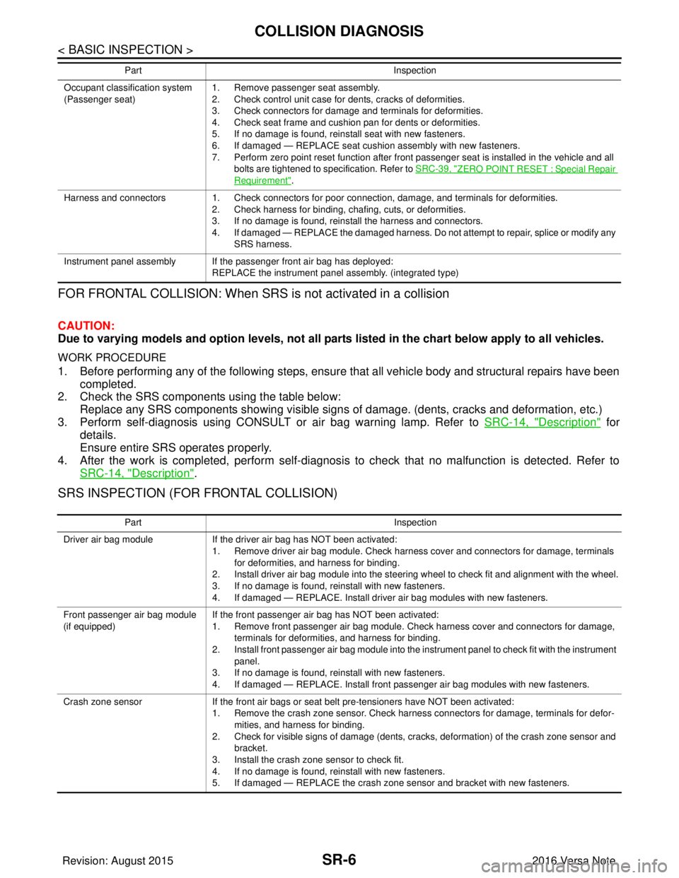
FOR FRONTAL COLLISION: When SRS is not activated in a collision
CAUTION:
Due to varying models and option levels, not all parts listed in the chart below apply to all vehicles.
WORK PROCEDURE
1. Before performing any of the following steps, ensure that all vehicle body and structural repairs have been
completed.
2. Check the SRS components using the table below: Replace any SRS components showing visible signs of damage. (dents, cracks and deformation, etc.)
3. Perform self-diagnosis using CONSULT or air bag warning lamp. Refer to SRC-14, "
Description" for
details.
Ensure entire SRS operates properly.
4. After the work is completed, perform self-diagnosis to check that no malfunction is detected. Refer to
SRC-14, "
Description".
SRS INSPECTION (FOR FRONTAL COLLISION)
Occupant classification system
(Passenger seat) 1. Remove passenger seat assembly.
2. Check control unit case for dents, cracks of deformities.
3. Check connectors for damage and terminals for deformities.
4. Check seat frame and cushion pan for dents or deformities.
5. If no damage is found, reinstall seat with new fasteners.
6. If damaged — REPLACE seat cushion assembly with new fasteners.
7. Perform zero point reset function after front passenger seat is installed in the vehicle and all
bolts are tightened to specification. Refer to SRC-39, "
ZERO POINT RESET : Special Repair
Requirement".
Harness and connectors 1. Check connectors for poor connection, damage, and terminals for deformities. 2. Check harness for binding, chafing, cuts, or deformities.
3. If no damage is found, reinstall the harness and connectors.
4. If damaged — REPLACE the damaged harness. Do not attempt to repair, splice or modify any SRS harness.
Instrument panel assembly If the passenger front air bag has deployed: REPLACE the instrument panel assembly. (integrated type)
Part
Inspection
Part Inspection
Driver air bag module If the driver air bag has NOT been activated:
1. Remove driver air bag module. Check harness cover and connectors for damage, terminals for deformities, and harness for binding.
2. Install driver air bag module into the steering wheel to check fit and alignment with the wheel.
3. If no damage is found, reinstall with new fasteners.
4. If damaged — REPLACE. Install driver air bag modules with new fasteners.
Front passenger air bag module
(if equipped) If the front passenger air bag has NOT been activated:
1. Remove front passenger air bag module. Check harness cover and connectors for damage,
terminals for deformities, and harness for binding.
2. Install front passenger air bag module into the instrument panel to check fit with the instrument panel.
3. If no damage is found, reinstall with new fasteners.
4. If damaged — REPLACE. Install front passenger air bag modules with new fasteners.
Crash zone sensor If the front air bags or seat belt pre-tensioners have NOT been activated:
1. Remove the crash zone sensor. Check harness connectors for damage, terminals for defor-
mities, and harness for binding.
2. Check for visible signs of damage (dents, cracks, deformation) of the crash zone sensor and bracket.
3. Install the crash zone sensor to check fit.
4. If no damage is found, reinstall with new fasteners.
5. If damaged — REPLACE the crash zone sensor and bracket with new fasteners.
Revision: August 2015 2016 Versa Note
cardiagn.com
Page 3123 of 3641
COLLISION DIAGNOSISSR-7
< BASIC INSPECTION >
C
DE
F
G
I
J
K L
M A
B
SR
N
O P
For Side and Rollover CollisionINFOID:0000000012430565
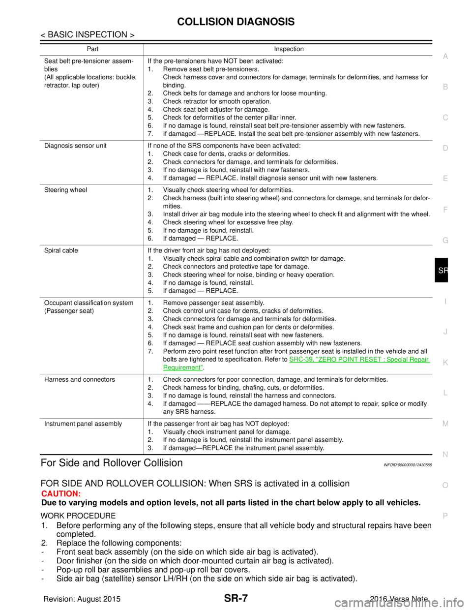
FOR SIDE AND ROLLOVER COLLISION: When SRS is activated in a collision
CAUTION:
Due to varying models and option levels, not all parts listed in the chart below apply to all vehicles.
WORK PROCEDURE
1. Before performing any of the following steps, ensur e that all vehicle body and structural repairs have been
completed.
2. Replace the following components:
- Front seat back assembly (on the side on which side air bag is activated).
- Door finisher (on the side on which door-mounted curtain air bag is activated).
- Pop-up roll bar assemblies and pop-up roll bar covers.
- Side air bag (satellite) sensor LH/RH (on the side on which side air bag is activated).
Seat belt pre-tensioner assem-
blies
(All applicable locations: buckle,
retractor, lap outer)If the pre-tensioners have NOT been activated:
1. Remove seat belt pre-tensioners.
Check harness cover and connectors for damage, terminals for deformities, and harness for
binding.
2. Check belts for damage and anchors for loose mounting.
3. Check retractor for smooth operation.
4. Check seat belt adjuster for damage.
5. Check for deformities of the center pillar inner.
6. If no damage is found, reinstall seat belt pre-tensioner assembly with new fasteners.
7. If damaged —REPLACE. Install the seat belt pre-tensioner assembly with new fasteners.
Diagnosis sensor unit If none of the SRS components have been activated:
1. Check case for dents, cracks or deformities.
2. Check connectors for damage, and terminals for deformities.
3. If no damage is found, reinstall with new fasteners.
4. If damaged — REPLACE. Install diagnosis sensor unit with new fasteners.
Steering wheel 1. Visually check steering wheel for deformities.
2. Check harness (built into steering wheel) and connectors for damage, and terminals for defor-
mities.
3. Install driver air bag module into the steering wheel to check fit and alignment with the wheel.
4. Check steering wheel for excessive free play.
5. If no damage is found, reinstall.
6. If damaged — REPLACE.
Spiral cable If the driver front air bag has not deployed:
1. Visually check spiral cable and combination switch for damage.
2. Check connectors and protective tape for damage.
3. Check steering wheel for noise, binding or heavy operation.
4. If no damage is found, reinstall.
5. If damaged — REPLACE.
Occupant classification system
(Passenger seat) 1. Remove passenger seat assembly.
2. Check control unit case for dents, cracks of deformities.
3. Check connectors for damage and terminals for deformities.
4. Check seat frame and cushion pan for dents or deformities.
5. If no damage is found, reinstall seat with new fasteners.
6. If damaged — REPLACE seat cushion assembly with new fasteners.
7. Perform zero point reset function after front passenger seat is installed in the vehicle and all
bolts are tightened to specification. Refer to SRC-39, "
ZERO POINT RESET : Special Repair
Requirement".
Harness and connectors 1. Check connectors for poor connection, damage, and terminals for deformities.
2. Check harness for binding, chafing, cuts, or deformities.
3. If no damage is found, reinstall the harness and connectors.
4. If damaged ——REPLACE the damaged harness. Do not attempt to repair, splice or modify
any SRS harness.
Instrument panel assembly If the passenger front air bag has NOT deployed: 1. Visually check instrument panel for damage.
2. If no damage is found, reinstall the instrument panel assembly.
3. If damaged—REPLACE the instrument panel assembly.
Part
Inspection
Revision: August 2015 2016 Versa Note
cardiagn.com
Page 3130 of 3641
SR-14
< REMOVAL AND INSTALLATION >
DRIVER AIR BAG MODULE
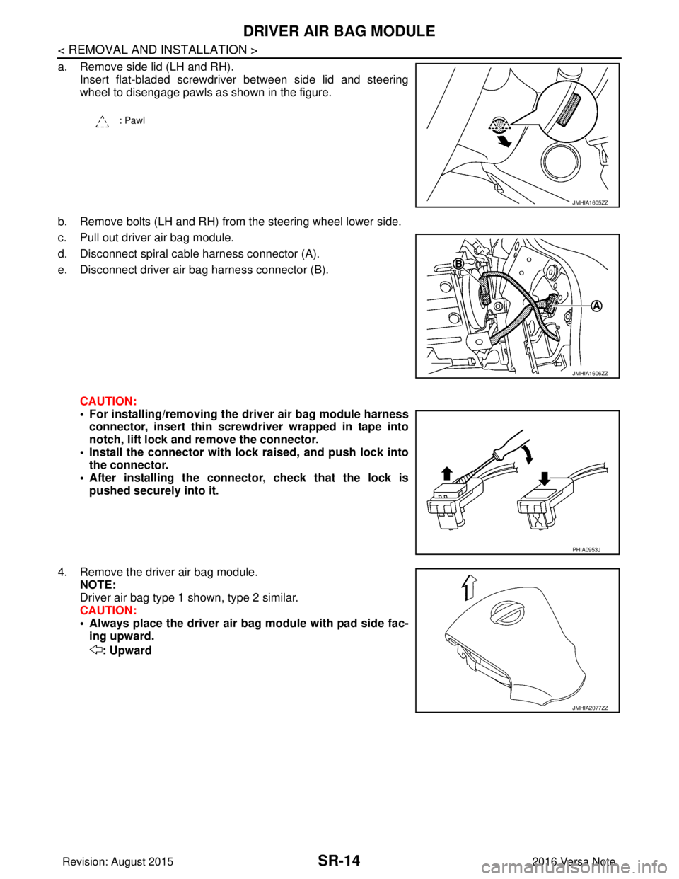
a. Remove side lid (LH and RH).Insert flat-bladed screwdriver between side lid and steering
wheel to disengage pawls as shown in the figure.
b. Remove bolts (LH and RH) from the steering wheel lower side.
c. Pull out driver air bag module.
d. Disconnect spiral cable harness connector (A).
e. Disconnect driver air bag harness connector (B).
CAUTION:
• For installing/removing the driver air bag module harnessconnector, insert thin screwdriver wrapped in tape into
notch, lift lock and remove the connector.
• Install the connector with lock raised, and push lock into
the connector.
• After installing the conn ector, check that the lock is
pushed securely into it.
4. Remove the driver air bag module. NOTE:
Driver air bag type 1 shown, type 2 similar.
CAUTION:
• Always place the driver air ba g module with pad side fac-
ing upward.
: Upward
: Pawl
JMHIA1605ZZ
JMHIA1606ZZ
PHIA0953J
JMHIA2077ZZ
Revision: August 2015 2016 Versa Note
cardiagn.com