2016 NISSAN NOTE wheel bolts
[x] Cancel search: wheel boltsPage 1623 of 3641
![NISSAN NOTE 2016 Service Repair Manual CO-18
< REMOVAL AND INSTALLATION >[HR16DE]
WATER PUMP
WATER PUMP
Exploded ViewINFOID:0000000012432144
Removal and InstallationINFOID:0000000012432145
WARNING:
Do not remove the radiator cap when the e](/manual-img/5/57363/w960_57363-1622.png "NISSAN NOTE 2016 Service Repair Manual CO-18
< REMOVAL AND INSTALLATION >[HR16DE]
WATER PUMP
WATER PUMP
Exploded ViewINFOID:0000000012432144
Removal and InstallationINFOID:0000000012432145
WARNING:
Do not remove the radiator cap when the e")
CO-18
< REMOVAL AND INSTALLATION >[HR16DE]
WATER PUMP
WATER PUMP
Exploded ViewINFOID:0000000012432144
Removal and InstallationINFOID:0000000012432145
WARNING:
Do not remove the radiator cap when the engine is hot. Serious burns could
occur from high-pressure
engine coolant escaping from the radi ator. Wrap a thick cloth around the radiator cap. Slowly turn it a
quarter of a turn to release built-up pressure. Carefu lly remove radiator cap by turning it all the way.
NOTE:
When removing components such as hoses, tubes/lines, etc. , cap or plug openings to prevent fluid from spill-
ing.
REMOVAL
1. Drain engine coolant from radiator. Refer to CO-8, "Draining Engine Coolant".
CAUTION:
• Perform this step when the engine is cold.
• Do not spill engine coolant on drive belt.
2. Remove front wheel and tire (RH) using power tool. Refer to WT-48, "
Removal and Installation".
3. Remove front fender protector (RH). Refer to EXT-38, "
Removal and Installation".
4. Loosen water pump pulley bolts before loosening belt tension of drive belt.
5. Remove drive belt. Refer to EM-16, "
Removal and Installation".
6. Remove water pump pulley.
7. Remove water pump. • Loosen water pump bolts in reverse order as shown.
• Engine coolant will leak from cylinder block, so have a recep-
tacle ready below.
CAUTION:
• Do not allow water pump vane to contact any other parts.
• Water pump cannot be disassembled and must be replaced as an assembly.
1. Gasket 2. Water pump3. Water pump pulley
JPBIA4104GB
KBIA3393J
Revision: August 2015 2016 Versa Note
cardiagn.com
Page 1822 of 3641
PREPARATIONFAX-5
< PREPARATION >
CEF
G H
I
J
K L
M A
B
FA X
N
O P
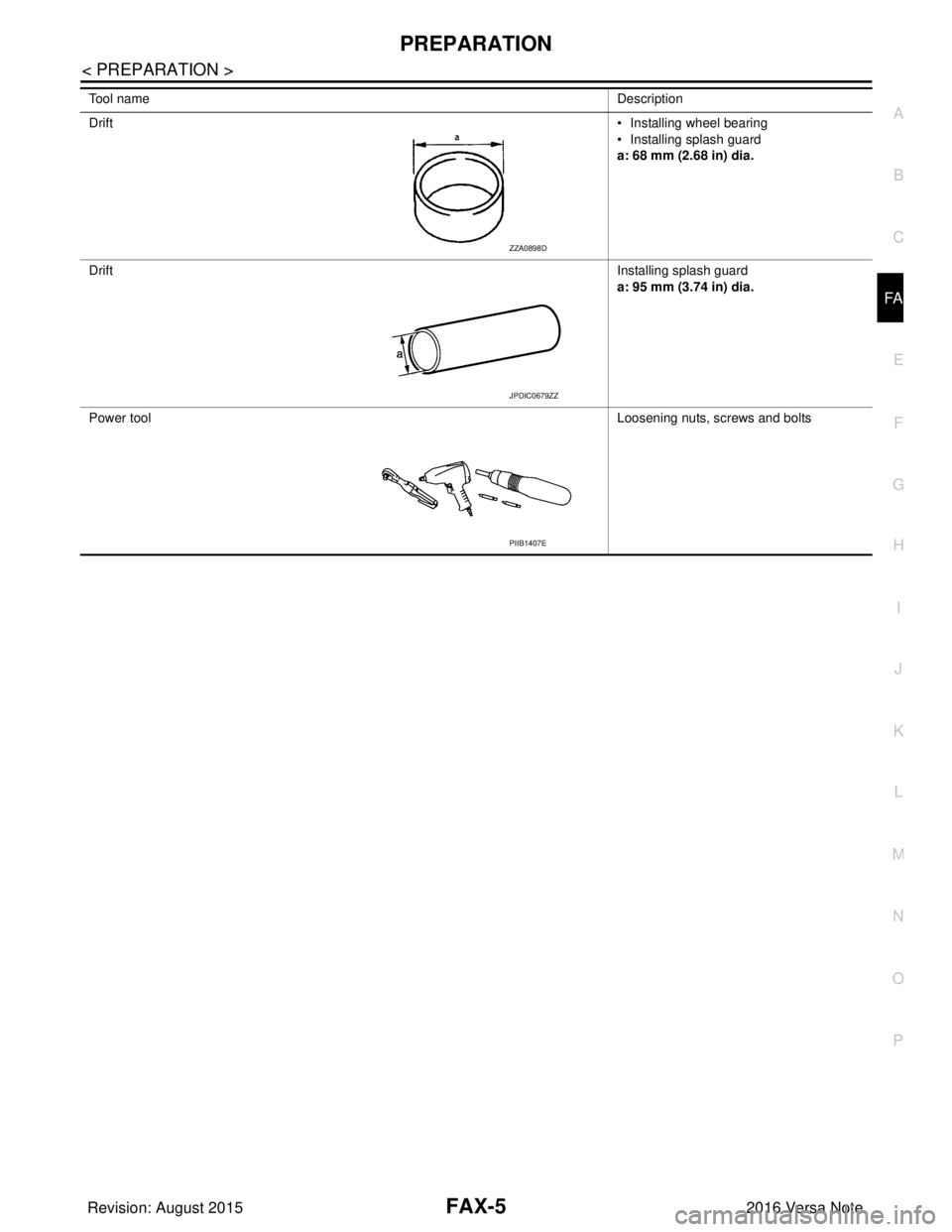
Drift • Installing wheel bearing
• Installing splash guard
a: 68 mm (2.68 in) dia.
Drift Installing splash guard
a: 95 mm (3.74 in) dia.
Power tool Loosening nuts, screws and bolts
Tool name
Description
ZZA0898D
JPDIC0679ZZ
PIIB1407E
Revision: August 2015 2016 Versa Note
cardiagn.com
Page 1827 of 3641
FAX-10
< REMOVAL AND INSTALLATION >
FRONT WHEEL HUB AND KNUCKLE
6. Separate the drive shaft from the wheel hub by lightly tapping the end of the drive shaft using a suitable
tool and a wood block.
NOTE:
Use suitable puller if wheel hub and drive shaft cannot be separated after performing the above proce-
dure.
7. Remove wheel hub lock nut.
8. Remove the nut and separate the steering out er socket from steering knuckle. Refer to ST-14, "
Exploded
View".
9. Remove the nuts and bolts, then separate the steering knuckle from strut. Refer to FA X - 9 , "
Removal and
Installation".
10. Suspend the drive shaft with suitable wire. CAUTION:
• Do not place drive shaft joint at an extreme angle. Also be careful not to overextend slide joint.
• Do not allow drive shaft to hang down withou t support for joint sub-assembly, shaft and the
other parts.
11. Remove transverse link outer nut and bolt. Remove steering knuckle from transverse link.
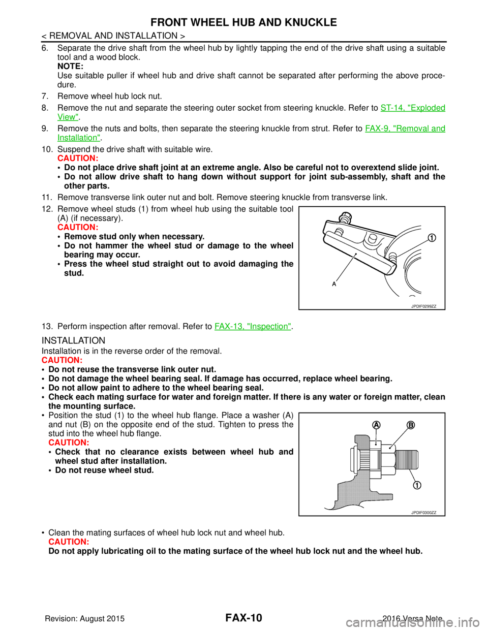
12. Remove wheel studs (1) from wheel hub using the suitable tool (A) (if necessary).
CAUTION:
• Remove stud only when necessary.
• Do not hammer the wheel stud or damage to the wheelbearing may occur.
• Press the wheel stud straight out to avoid damaging the stud.
13. Perform inspection after removal. Refer to FAX-13, "
Inspection".
INSTALLATION
Installation is in the reverse order of the removal.
CAUTION:
• Do not reuse the transverse link outer nut.
• Do not damage the wheel bearing seal. If damage has occurred, replace wheel bearing.
• Do not allow paint to adhere to the wheel bearing seal.
• Check each mating surface for water and foreign matter. If there is any water or foreign matter, clean
the mounting surface.
• Position the stud (1) to the wheel hub flange. Place a washer (A) and nut (B) on the opposite end of the stud. Tighten to press the
stud into the wheel hub flange.
CAUTION:
• Check that no clearance exists between wheel hub andwheel stud after installation.
• Do not reuse wheel stud.
• Clean the mating surfaces of wheel hub lock nut and wheel hub. CAUTION:
Do not apply lubricatin g oil to the mating surface of the wh eel hub lock nut and the wheel hub.
JPDIF0299ZZ
JPDIF0300ZZ
Revision: August 2015 2016 Versa Note
cardiagn.com
Page 1832 of 3641

FRONT DRIVE SHAFT BOOTFAX-15
< REMOVAL AND INSTALLATION >
CEF
G H
I
J
K L
M A
B
FA X
N
O P
WHEEL SIDE : Removal and InstallationINFOID:0000000012431895
REMOVAL
1. Remove the wheel and tire using power tool. Refer to WT-48, "Removal and Installation".
2. Remove the brake caliper torque member bolts, leav ing the brake hose attached. Position the brake cali-
per aside with wire. Refer to BR-37, "
BRAKE CALIPER ASSEMBLY : Removal and Installation".
CAUTION:
Do not depress the brake pedal while the brake caliper is removed.
3. Put alignment marks on the disc brake rotor and on the wheel hub. Remove the disc brake rotor.
CAUTION:
Do not drop the disc brake rotor.
4. Remove the wheel sensor bolt. Position the wheel sensor and the wheel sensor harness aside. Refer to
BRC-140, "
FRONT WHEEL SENSOR : Removal and Installation".
5. Remove the cotter pin from the drive shaft.
6. Hold the wheel hub using Tool. Loosen the wheel hub lock nut.
7. Using a piece of wood and a suitable tool, tap on the wheel hub lock nut to disengage the drive shaft from the wheel hub.
CAUTION:
• Do not place the drive shaft joint at an extreme angle. Also be careful not to overextend slide
joint.
• Do not allow the drive shaft to hang down without support.
NOTE:
Use a suitable puller if the drive shaft cannot be separated from the wheel hub even after performing the
above procedure.
8. Remove the wheel hub lock nut.
9. Remove the nut and bolt from the lower ball joint. Disconnect the steering knuckle from the transverse
link.
10. Remove the drive shaft from the wheel hub.
11. Remove the boot bands.
12. Separate the boot from the joint sub-assembly.
13. Screw a suitable tool (A) into the joint sub-assembly screw part to a length of 30 mm (1.18 in) or more. Support the drive shaft
with one hand and pull out the joint sub-assembly from the shaft.
CAUTION:
• Align the suitable tool an d the drive shaft. Remove the
joint sub-assembly by pull ing firmly and uniformly.
• If the joint sub-assembly cannot be pulled out, try after removing the drive shaft from the vehicle. Refer to FA X -
22, "Disassembly and Assembly".
14. Remove the circular clip (1) from the shaft.
15. Remove the outer boot from the shaft. Tool number : KV4010104000 ( — )
JPDIF0258ZZ
JPDIF0007ZZ
Revision: August 2015
2016 Versa Note
cardiagn.com
Page 1835 of 3641
FAX-18
< REMOVAL AND INSTALLATION >
FRONT DRIVE SHAFT BOOT
• Check each mating surface for water and foreign matter. If there is any water or foreign matter,
clean the mating surface.
17. Install the transverse link to the steering knuckle with the nut and bolt. Refer to FSU-10, "
Exploded View".
18. Hold the wheel hub using a Tool. Tighten the wheel hub lock nut. CAUTION:
• Since the drive shaft is assembled by press-fitting, use a torque wrench to tighten the wheel hub
lock nut. Do not use a power tool.
• Too much torque causes axle noise. Too little torque causes wheel bearing looseness. Tighten the wheel hub lock nut to the specification.
19. Install the cotter pin. Securely bend the cotter pin to prevent rattles. CAUTION:
Do not reuse the cotter pin.
20. Install the wheel sensor, the wheel sensor bolt, and the wheel sensor harness. Refer to BRC-140,
"FRONT WHEEL SENSOR : Removal and Installation".
21. Align the matching marks on the disc brake roto r and on the wheel hub. Install the disc brake rotor.
CAUTION:
Do not drop the disc brake rotor.
22. Remove the wire from the brake caliper. Install the brake caliper and the brake caliper torque member
bolts. Refer to BR-37, "
BRAKE CALIPER ASSEMBLY : Removal and Installation".
CAUTION:
Do not twist the brake hose.
23. Install the wheel and tire. Refer to WT-48, "
Removal and Installation".
24. Complete the inspection. Refer to FAX-18, "
Inspection".
TRANSAXLE SIDE
TRANSAXLE SIDE : Removal and InstallationINFOID:0000000012431896
Remove boot after drive shaft is removed from the vehicle.
• For drive shaft removal and installation, refer to FAX-19, "
Removal and Installation".
• For drive shaft disassembly and assembly, refer to FAX-22, "
Disassembly and Assembly".
InspectionINFOID:0000000012431897
INSPECTION AFTER INSTALLATION
1. Check the wheel sensor harness to be sure the connectors are fully seated.
2. Check the wheel alignment. Refer to FSU-7, "
Inspection".
Tool number : KV4010104000 ( — )
Revision: August 2015
2016 Versa Note
cardiagn.com
Page 1836 of 3641
FRONT DRIVE SHAFTFAX-19
< REMOVAL AND INSTALLATION >
CEF
G H
I
J
K L
M A
B
FA X
N
O P
FRONT DRIVE SHAFT
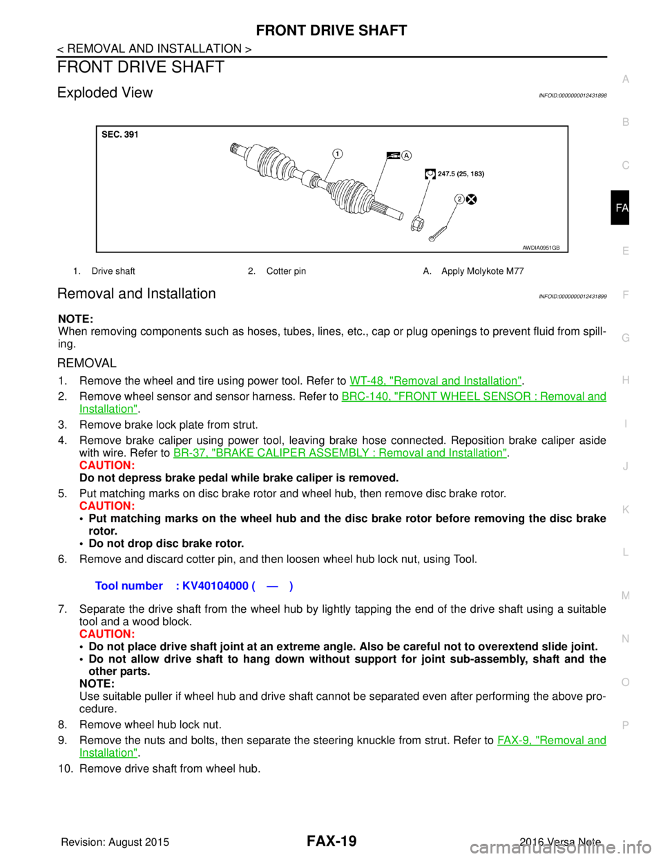
Exploded ViewINFOID:0000000012431898
Removal and InstallationINFOID:0000000012431899
NOTE:
When removing components such as hoses, tubes, lines, etc. , cap or plug openings to prevent fluid from spill-
ing.
REMOVAL
1. Remove the wheel and tire using power tool. Refer to WT-48, "Removal and Installation".
2. Remove wheel sensor and sensor harness. Refer to BRC-140, "
FRONT WHEEL SENSOR : Removal and
Installation".
3. Remove brake lock plate from strut.
4. Remove brake caliper using power tool, leaving brake hose connected. Reposition brake caliper aside with wire. Refer to BR-37, "
BRAKE CALIPER ASSEMBLY : Removal and Installation".
CAUTION:
Do not depress brake pedal while brake caliper is removed.
5. Put matching marks on disc brake rotor and wheel hub, then remove disc brake rotor. CAUTION:
• Put matching marks on the wheel hub and the disc brake rotor before removing the disc brake
rotor.
• Do not drop disc brake rotor.
6. Remove and discard cotter pin, and then loosen wheel hub lock nut, using Tool.
7. Separate the drive shaft from the wheel hub by lightly tapping the end of the drive shaft using a suitable tool and a wood block.
CAUTION:
• Do not place drive shaft joint at an extreme angle. Also be careful not to overextend slide joint.
• Do not allow drive shaft to ha ng down without support for joint sub-assembly, shaft and the
other parts.
NOTE:
Use suitable puller if wheel hub and drive shaft cannot be separated even after performing the above pro-
cedure.
8. Remove wheel hub lock nut.
9. Remove the nuts and bolts, then separate the steering knuckle from strut. Refer to FA X - 9 , "
Removal and
Installation".
10. Remove drive shaft from wheel hub.
1. Drive shaft 2. Cotter pinA. Apply Molykote M77
AWDIA0951GB
Tool number : KV40104000 ( — )
Revision: August 2015 2016 Versa Note
cardiagn.com
Page 1854 of 3641
FRONT COIL SPRING AND STRUTFSU-9
< REMOVAL AND INSTALLATION >
C
DF
G H
I
J
K L
M A
B
FSU
N
O P
REMOVAL AND INSTALLATION
FRONT COIL SPRING AND STRUT
Exploded ViewINFOID:0000000012430303
Removal and InstallationINFOID:0000000012430304
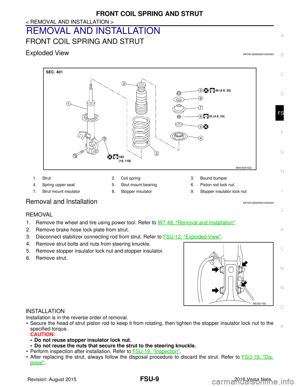
REMOVAL
1. Remove the wheel and tire using power tool. Refer to WT-48, "Removal and Installation".
2. Remove brake hose lock plate from strut.
3. Disconnect stabilizer connecting rod from strut. Refer to FSU-12, "
Exploded View".
4. Remove strut bolts and nuts from steering knuckle.
5. Remove stopper insulator lock nut and stopper insulator.
6. Remove strut.
INSTALLATION
Installation is in the reverse order of removal.
• Secure the head of strut piston rod to keep it from rotating, then tighten the stopper insulator lock nut to the specified torque.
CAUTION:
• Do not reuse stopper insulator lock nut.
• Do not reuse the nuts that secure the strut to the steering knuckle.
• Perform inspection after installation. Refer to FSU-19, "
Inspection".
• After replacing the strut, always follow the dis posal procedure to discard the strut. Refer to FSU-19, "
Dis-
posal".
1. Strut2. Coil spring3. Bound bumper
4. Spring upper seat 5. Strut mount bearing6. Piston rod lock nut
7. Strut mount insulator 8. Stopper insulator9. Stopper insulator lock nut
AWEIA0418ZZ
WEIA0179E
Revision: August 2015 2016 Versa Note
cardiagn.com
Page 1855 of 3641
FSU-10
< REMOVAL AND INSTALLATION >
TRANSVERSE LINK
TRANSVERSE LINK
Exploded ViewINFOID:0000000012430305
Removal and InstallationINFOID:0000000012430306
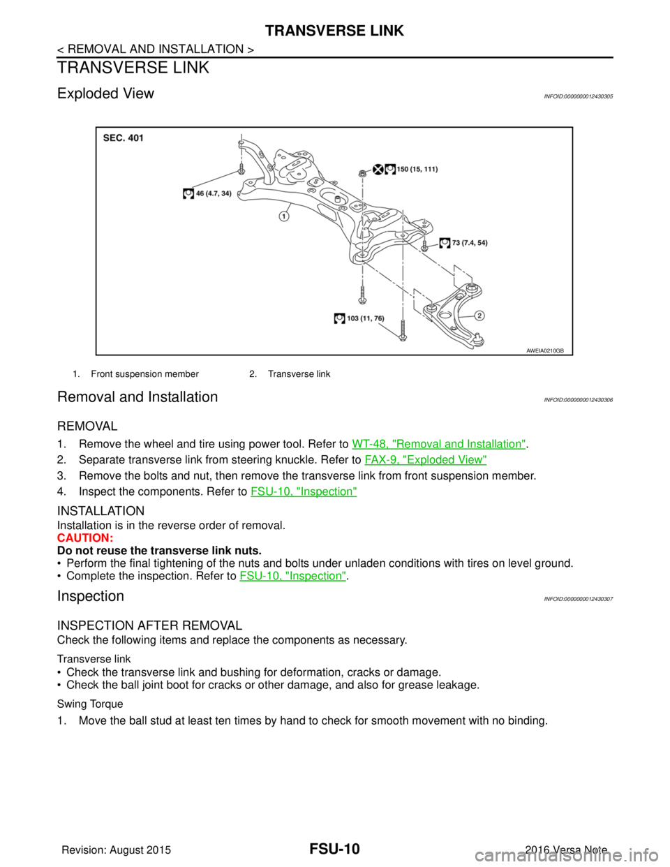
REMOVAL
1. Remove the wheel and tire using power tool. Refer to WT-48, "Removal and Installation".
2. Separate transverse link from steering knuckle. Refer to FA X - 9 , "
Exploded View"
3. Remove the bolts and nut, then remove the transverse link from front suspension member.
4. Inspect the components. Refer to FSU-10, "
Inspection"
INSTALLATION
Installation is in the reverse order of removal.
CAUTION:
Do not reuse the transverse link nuts.
• Perform the final tightening of the nuts and bolts under unladen conditions with tires on level ground.
• Complete the inspection. Refer to FSU-10, "
Inspection".
InspectionINFOID:0000000012430307
INSPECTION AFTER REMOVAL
Check the following items and replace the components as necessary.
Transverse link
• Check the transverse link and bushing for deformation, cracks or damage.
• Check the ball joint boot for cracks or other damage, and also for grease leakage.
Swing Torque
1. Move the ball stud at least ten times by hand to check for smooth movement with no binding.
1. Front suspension member2. Transverse link
AWEIA0210GB
Revision: August 2015 2016 Versa Note
cardiagn.com