2016 NISSAN NOTE wheel bolts
[x] Cancel search: wheel boltsPage 1857 of 3641
FSU-12
< REMOVAL AND INSTALLATION >
FRONT STABILIZER
FRONT STABILIZER
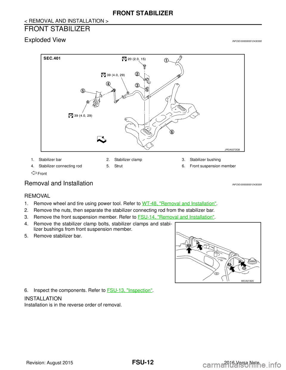
Exploded ViewINFOID:0000000012430308
Removal and InstallationINFOID:0000000012430309
REMOVAL
1. Remove wheel and tire using power tool. Refer to WT-48, "Removal and Installation".
2. Remove the nuts, then separate the stabilizer connecting rod from the stabilizer bar.
3. Remove the front suspension member. Refer to FSU-14, "
Removal and Installation".
4. Remove the stabilizer clamp bolts, stabilizer clamps and stabi- lizer bushings from front suspension member.
5. Remove stabilizer bar.
6. Inspect the components. Refer to FSU-13, "
Inspection".
INSTALLATION
Installation is in the reverse order of removal.
1. Stabilizer bar 2. Stabilizer clamp 3. Stabilizer bushing
4. Stabilizer connecting rod 5. Strut 6. Front suspension member
Front
JPEIA0272GB
WEIA0182E
Revision: August 2015 2016 Versa Note
cardiagn.com
Page 1858 of 3641
FRONT STABILIZERFSU-13
< REMOVAL AND INSTALLATION >
C
DF
G H
I
J
K L
M A
B
FSU
N
O P
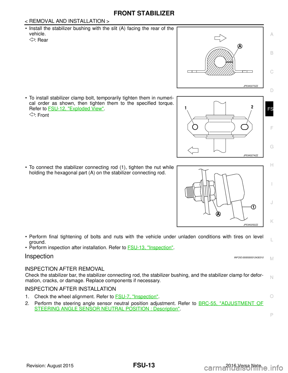
• Install the stabilizer bushing with the slit (A) facing the rear of the vehicle.
: Rear
• To install stabilizer clamp bolt, temporarily tighten them in numeri- cal order as shown, then tighten them to the specified torque.
Refer to FSU-12, "
Exploded View".
: Front
• To connect the stabilizer connecting rod (1), tighten the nut while holding the hexagonal part (A) on the stabilizer connecting rod.
• Perform final tightening of bolts and nuts with the vehicle under unladen conditions with tires on level ground.
• Perform inspection after installation. Refer to FSU-13, "
Inspection".
InspectionINFOID:0000000012430310
INSPECTION AFTER REMOVAL
Check the stabilizer bar, the stabilizer connecting rod, t he stabilizer bushing, and the stabilizer clamp for defor-
mation, cracks, or damage. Replace components if necessary.
INSPECTION AFTER INSTALLATION
1. Check the wheel alignment. Refer to FSU-7, "Inspection".
2. Perform the steering angle sensor neutral position adjustment. Refer to BRC-55, "
ADJUSTMENT OF
STEERING ANGLE SENSOR NEUTRAL POSITION : Description".
JPEIA0273ZZ
JPEIA0274ZZ
JPEIA0252ZZ
Revision: August 2015 2016 Versa Note
cardiagn.com
Page 1859 of 3641
FSU-14
< UNIT REMOVAL AND INSTALLATION >
FRONT SUSPENSION MEMBER
UNIT REMOVAL AND INSTALLATION
FRONT SUSPENSION MEMBER
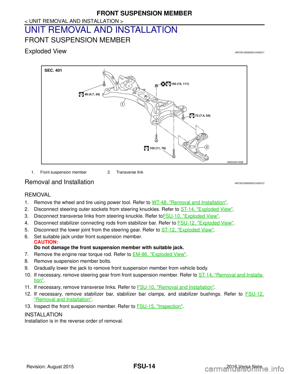
Exploded ViewINFOID:0000000012430311
Removal and InstallationINFOID:0000000012430312
REMOVAL
1. Remove the wheel and tire using power tool. Refer to WT-48, "Removal and Installation".
2. Disconnect steering outer sockets from steering knuckles. Refer to ST-14, "
Exploded View".
3. Disconnect transverse links from steering knuckle. Refer to FSU-10, "
Exploded View".
4. Disconnect stabilizer connecting rods from stabilizer bar. Refer to FSU-12, "
Exploded View".
5. Disconnect the lower joint from the steering gear. Refer to ST-12, "
Exploded View".
6. Set suitable jack under front suspension member. CAUTION:
Do not damage the front suspensi on member with suitable jack.
7. Remove the engine rear torque rod. Refer to EM-86, "
Exploded View".
8. Remove suspension member bolts.
9. Gradually lower the jack to remove front suspension member from vehicle body.
10. If necessary, remove steering gear from front suspension member. Refer to ST-14, "
Removal and Installa-
tion".
11. If necessary, remove transverse links. Refer to FSU-10, "
Removal and Installation".
12. If necessary, remove stabilizer bar, stabilizer bar clamps, and stabilizer bushings. Refer to FSU-12,
"Removal and Installation".
13. Inspect the front suspension member. Refer to FSU-15, "
Inspection".
INSTALLATION
Installation is in the reverse order of removal.
1. Front suspension member2. Transverse link
AWEIA0210GB
Revision: August 2015 2016 Versa Note
cardiagn.com
Page 1860 of 3641
FRONT SUSPENSION MEMBERFSU-15
< UNIT REMOVAL AND INSTALLATION >
C
DF
G H
I
J
K L
M A
B
FSU
N
O P
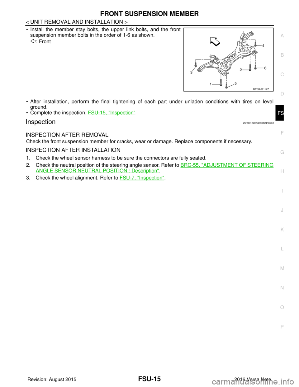
• Install the member stay bolts, the upper link bolts, and the front suspension member bolts in the order of 1-6 as shown.
: Front
• After installation, perform the final tightening of each part under unladen conditions with tires on level
ground.
• Complete the inspection. FSU-15, "
Inspection"
InspectionINFOID:0000000012430313
INSPECTION AFTER REMOVAL
Check the front suspension member for cracks, wear or damage. Replace components if necessary.
INSPECTION AFTER INSTALLATION
1. Check the wheel sensor harness to be sure the connectors are fully seated.
2. Check the neutral position of the steering angle sensor. Refer to BRC-55, "
ADJUSTMENT OF STEERING
ANGLE SENSOR NEUTRAL POSITION : Description".
3. Check the wheel alignment. Refer to FSU-7, "
Inspection".
AWEIA0211ZZ
Revision: August 2015 2016 Versa Note
cardiagn.com
Page 1889 of 3641

GI-1
GENERAL INFORMATION
C
DE
F
G H
I
J
K L
M B
GI
SECTION GI
N
O P
CONTENTS
GENERAL INFORMATION
HOW TO USE THIS MANU AL ......................3
HOW TO USE THIS MANUAL ....................... .....3
Description .......................................................... ......3
Terms ........................................................................3
Units ..........................................................................3
Contents ....................................................................3
Relation between Illustrations and Descriptions .......4
Components ..............................................................4
HOW TO FOLLOW TROUBLE DIAGNOSES .....6
Description ................................................................6
How to Follow Test Groups in Trouble Diagnosis ......6
Key to Symbols Signifying Measurements or Pro-
cedures ............................................................... ......
7
HOW TO READ WIRING DIAGRAMS ................9
Connector Symbols ............................................. ......9
Sample/Wiring Diagram -Example- .........................10
Connector Information .............................................12
ABBREVIATIONS .......................................... ....14
Abbreviation List .................................................. ....14
TIGHTENING TORQUE OF STANDARD
BOLTS ................................................................
19
Description .......................................................... ....19
Tightening Torque Table (New Standard Includ-
ed) ...........................................................................
19
RECOMMENDED CHEMICAL PRODUCTS
AND SEALANTS ................................................
22
Recommended Chemical Products and Sealants ....22
PRECAUTION ..............................................23
PRECAUTIONS .............................................. ....23
Description .......................................................... ....23
Precaution for Supplemental Restraint System
(SRS) "AIR BAG" and "SEAT BELT PRE-TEN-
SIONER" .................................................................
23
Procedures without Cowl Top Cover .......................23
Cautions in Removing Battery Terminal and AV
Control Unit (Models with AV Control Unit) .............
23
General Precautions ............................................ ....24
Three Way Catalyst .................................................25
Fuel ..........................................................................25
Multiport Fuel Injection System or Engine Control
System .....................................................................
26
Hoses ......................................................................26
Engine Oils ..............................................................27
Air Conditioning .......................................................27
LIFTING POINT .................................................28
Special Service Tool ................................................28
Garage Jack and Safety Stand ................................28
2-Pole Lift ................................................................29
Board-on Lift ............................................................30
TOW TRUCK TOWING .....................................31
Tow Truck Towing ...................................................31
Vehicle Recovery (Freeing a Stuck Vehicle) ...........31
VEHICLE INFORMATION ...........................33
IDENTIFICATION INFORMATION ....................33
Model Variation .................................................... ....33
Identification Number ...............................................34
Identification Plate ...................................................35
Engine Serial Number .............................................36
CVT Number ............................................................36
Manual Transaxle Number ......................................36
Dimensions ..............................................................36
Wheels & Tires ........................................................37
BASIC INSPECTION ...................................38
SERVICE INFORMATION FOR ELECTRICAL
INCIDENT ..........................................................
38
Work Flow ............................................................ ....38
Control Units and Electrical Parts ............................38
How to Check Terminal ...........................................39
Intermittent Incident ............................................. ....42
Circuit Inspection .....................................................44
Revision: August 2015 2016 Versa Note
cardiagn.com
Page 2085 of 3641
STEERING COLUMN COVERSIP-17
< REMOVAL AND INSTALLATION >
C
DE
F
G H
I
K L
M A
B
IP
N
O P
STEERING COLUMN COVERS
Removal and InstallationINFOID:0000000012430779
REMOVAL
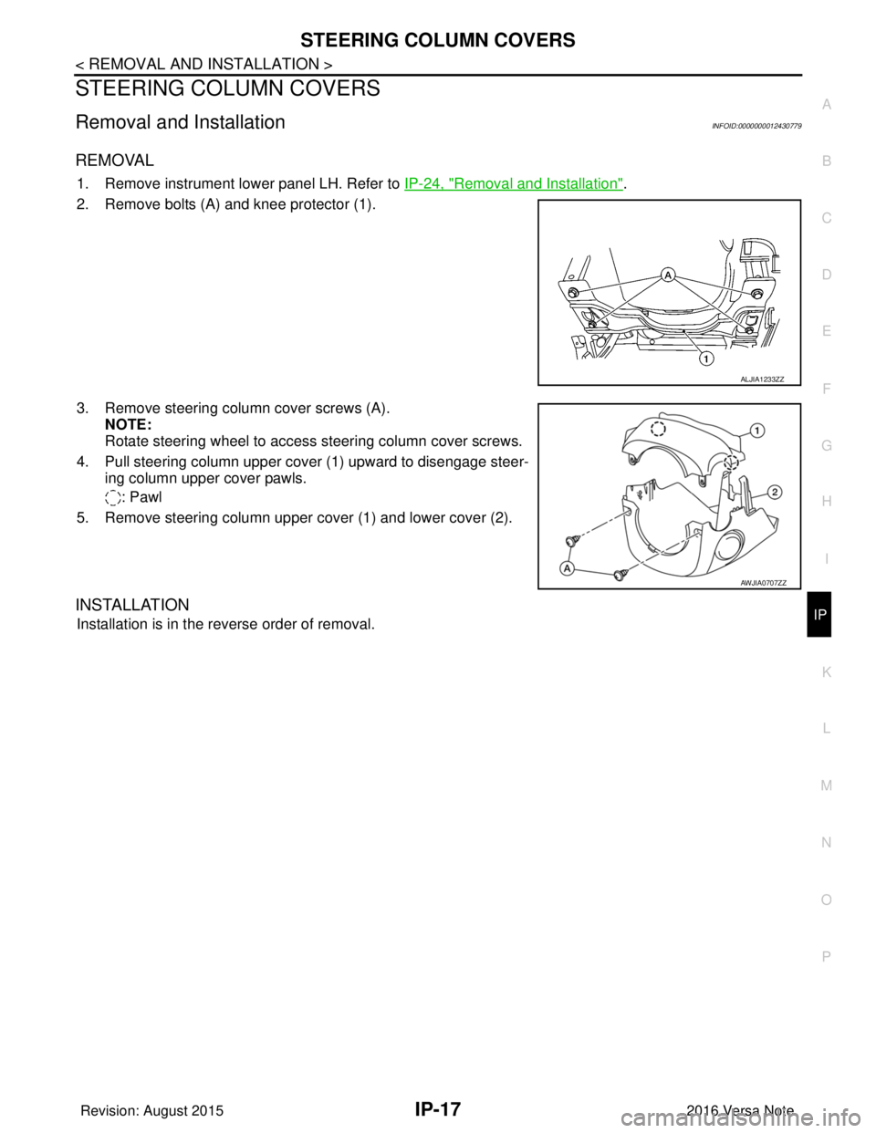
1. Remove instrument lower panel LH. Refer to IP-24, "Removal and Installation".
2. Remove bolts (A) and knee protector (1).
3. Remove steering column cover screws (A). NOTE:
Rotate steering wheel to access steering column cover screws.
4. Pull steering column upper cover (1) upward to disengage steer- ing column upper cover pawls.
: Pawl
5. Remove steering column upper cover (1) and lower cover (2).
INSTALLATION
Installation is in the reverse order of removal.
ALJIA1233ZZ
AWJIA0707ZZ
Revision: August 2015 2016 Versa Note
cardiagn.com
Page 2354 of 3641
CHASSIS AND BODY MAINTENANCEMA-39
< PERIODIC MAINTENANCE >
C
DE
F
G H
I
J
K L
M B
MA
N
O A
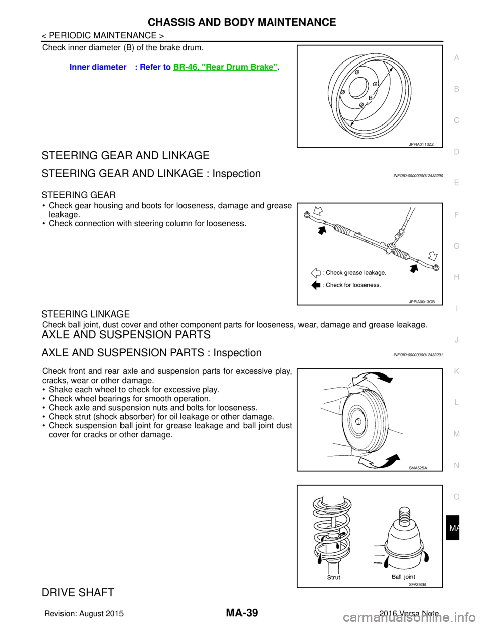
Check inner diameter (B) of the brake drum.
STEERING GEAR AND LINKAGE
STEERING GEAR AND LINKAGE : InspectionINFOID:0000000012432290
STEERING GEAR
• Check gear housing and boots for looseness, damage and grease
leakage.
• Check connection with steering column for looseness.
STEERING LINKAGE
Check ball joint, dust cover and other component parts for looseness, wear, damage and grease leakage.
AXLE AND SUSPENSION PARTS
AXLE AND SUSPENSION PARTS : InspectionINFOID:0000000012432291
Check front and rear axle and suspension parts for excessive play,
cracks, wear or other damage.
• Shake each wheel to check for excessive play.
• Check wheel bearings for smooth operation.
• Check axle and suspension nuts and bolts for looseness.
• Check strut (shock absorber) for oil leakage or other damage.
• Check suspension ball joint for grease leakage and ball joint dust
cover for cracks or other damage.
DRIVE SHAFT
Inner diameter : Refer to BR-46, "Rear Drum Brake".
JPFIA0113ZZ
JPPIA0013GB
SMA525A
SFA392B
Revision: August 2015 2016 Versa Note
cardiagn.com
Page 2501 of 3641
PB-8
< REMOVAL AND INSTALLATION >
PARKING BRAKE REAR CABLE
PARKING BRAKE REAR CABLE
Removal and InstallationINFOID:0000000012430692
REMOVAL
1. Remove the center console assembly. Refer to IP-18, "Removal and Installation".
2. Loosen the adjusting nut. Refer to PB-6, "
Exploded View".
NOTE:
It is not necessary to remove the parking brake front cable.
3. Separate the parking brake rear cables (RH/LH ) from the parking brake front cable. Refer to PB-6,
"Exploded View".
4. Remove the rear wheels and tires using power tool. Refer to WT-48, "
Exploded View".
5. Remove rear wheel sensors. Refer to BRC-143, "
REAR SENSOR ROTOR : Removal and Installation".
6. Remove the rear drum brake components. Refer to BR-41, "
Removal and Installation".
CAUTION:
Do not separate the brake tube from the wheel cylinders.
7. Remove the center muffler. Refer to EX-5, "
Exploded View".
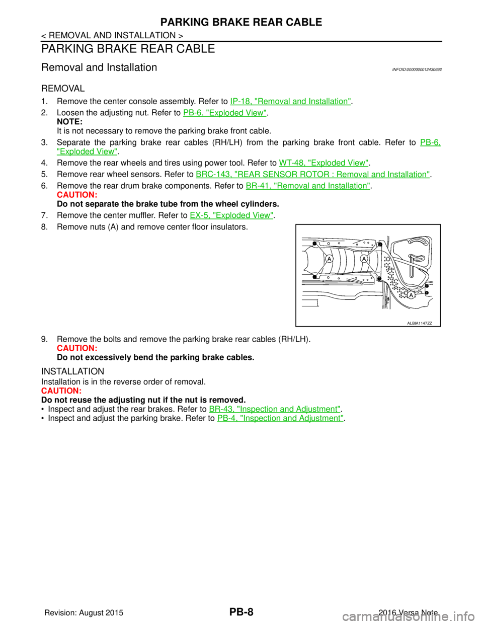
8. Remove nuts (A) and remove center floor insulators.
9. Remove the bolts and remove the parking brake rear cables (RH/LH). CAUTION:
Do not excessively bend the parking brake cables.
INSTALLATION
Installation is in the reverse order of removal.
CAUTION:
Do not reuse the adjusting nut if the nut is removed.
• Inspect and adjust the rear brakes. Refer to BR-43, "
Inspection and Adjustment".
• Inspect and adjust the parking brake. Refer to PB-4, "
Inspection and Adjustment".
ALBIA1147ZZ
Revision: August 2015 2016 Versa Note
cardiagn.com