2016 NISSAN NOTE oil type
[x] Cancel search: oil typePage 1416 of 3641
![NISSAN NOTE 2016 Service Repair Manual P0420 THREE WAY CATALYST FUNCTIONEC-289
< DTC/CIRCUIT DIAGNOSIS > [HR16DE]
C
D
E
F
G H
I
J
K L
M A
EC
NP
O
Check the initial spark plug for fouling, etc.
Is the inspection result normal?
YES >> Replac NISSAN NOTE 2016 Service Repair Manual P0420 THREE WAY CATALYST FUNCTIONEC-289
< DTC/CIRCUIT DIAGNOSIS > [HR16DE]
C
D
E
F
G H
I
J
K L
M A
EC
NP
O
Check the initial spark plug for fouling, etc.
Is the inspection result normal?
YES >> Replac](/manual-img/5/57363/w960_57363-1415.png)
P0420 THREE WAY CATALYST FUNCTIONEC-289
< DTC/CIRCUIT DIAGNOSIS > [HR16DE]
C
D
E
F
G H
I
J
K L
M A
EC
NP
O
Check the initial spark plug for fouling, etc.
Is the inspection result normal?
YES >> Replace spark plug(s) with standard type one(s). For
spark plug type, refer to EM-117, "
Spark Plug".
NO >> Repair or clean spark plug. Then GO TO 9
9.CHECK FUNCTION OF IGNITION COIL-III
1. Reconnect the initial spark plugs.
2. Crank engine for about 3 seconds, and recheck whether spark is generated between the spark plug and the grounded portion.
Is the inspection result normal?
YES >> INSPECTION END
NO >> Replace spark plug(s) with standard type one(s). For spark plug type, refer to EM-117, "
Spar k
Plug".
10.CHECK FUEL INJECTOR
1. Turn ignition switch OFF.
2. Remove fuel injector assembly. Refer to EM-40, "
Removal and Installation".
Keep fuel hose and all fuel injectors connected to fuel tube.
3. Disconnect all ignition coil harness connectors.
4. Reconnect all fuel injector harness connectors disconnected.
5. Turn ignition switch ON.
Does fuel drip from fuel injector?
YES >> GO TO 11.
NO >> Replace the fuel injector(s) from which fuel is dripping. Refer to EM-40, "
Removal and Installa-
tion".
11 .CHECK INTERMITTENT INCIDENT
Refer to GI-42, "
Intermittent Incident".
Is the trouble fixed?
YES >> INSPECTION END
NO >> Replace three way catalyst assembly. Refer to EX-5, "
Exploded View".
SEF156I
Spark should be generated.
Revision: August 2015 2016 Versa Note
cardiagn.com
Page 1557 of 3641
![NISSAN NOTE 2016 Service Repair Manual EC-430
< DTC/CIRCUIT DIAGNOSIS >[HR16DE]
P219A AIR FUEL RATIO
Check compression pressure. Refer to
EM-13, "Inspection".
Is the inspection result normal?
YES >> Check intermittent incident. Refer to NISSAN NOTE 2016 Service Repair Manual EC-430
< DTC/CIRCUIT DIAGNOSIS >[HR16DE]
P219A AIR FUEL RATIO
Check compression pressure. Refer to
EM-13, "Inspection".
Is the inspection result normal?
YES >> Check intermittent incident. Refer to](/manual-img/5/57363/w960_57363-1556.png)
EC-430
< DTC/CIRCUIT DIAGNOSIS >[HR16DE]
P219A AIR FUEL RATIO
Check compression pressure. Refer to
EM-13, "Inspection".
Is the inspection result normal?
YES >> Check intermittent incident. Refer to GI-42, "Intermittent Incident".
NO >> Check pistons, piston rings, valves, valve seats and cylinder head gaskets.
9.DETECT MALFUNCTIONING PART
Check fuel hoses and fuel tubes for clogging.
Is the inspection result normal?
YES >> Replace fuel filter and fuel pump assembly. Refer to FL-6, "Exploded View".
NO >> Repair or replace error-detected parts.
10.CHECK FUNCTION OF IGNITION COIL-2
1. Turn ignition switch OFF.
2. Disconnect spark plug and connect a non-malfunctioning spark plug.
3. Crank engine for approximately 3 seconds, and rec heck whether spark is generated between the spark
plug and the grounded metal portion.
Is the inspection result normal?
YES >> GO TO 11.
NO >> Check ignition coil, power transistor and their circuits. Refer to EC-451, "
Component Function
Check".
11 .CHECK SPARK PLUG
Check the initial spark plug for fouling, etc.
Is the inspection result normal?
YES >> 1. Repair or clean spark plug. Refer to EM-47,
"Exploded View".
2. GO TO 12.
NO >> Replace spark plug(s) with standard type one(s). For spark plug type, refer to EM-117, "
Spark Plug".
12.CHECK FUNCTION OF IGNITION COIL-3
1. Reconnect the initial spark plugs.
2. Crank engine for approximately 3 seconds, and rec heck whether spark is generated between the spark
plug and the grounded portion.
Is the inspection result normal?
YES >> Check intermittent incident. Refer to GI-42, "Intermittent Incident".
NO >> Replace spark plug(s) with standard type one(s). For spark plug type, refer to EM-117, "
Spark
Plug".
Spark should be generated.
SEF156I
Spark should be generated.
Revision: August 2015
2016 Versa Note
cardiagn.com
Page 1562 of 3641
![NISSAN NOTE 2016 Service Repair Manual P219C, P219D, P219E, P219F AIR FUEL RATIO
EC-435
< DTC/CIRCUIT DIAGNOSIS > [HR16DE]
C
D
E
F
G H
I
J
K L
M A
EC
NP
O
10. Allow a 13-17mm (0.52-0.66 in) spacing between spark plug and
grounded metal por NISSAN NOTE 2016 Service Repair Manual P219C, P219D, P219E, P219F AIR FUEL RATIO
EC-435
< DTC/CIRCUIT DIAGNOSIS > [HR16DE]
C
D
E
F
G H
I
J
K L
M A
EC
NP
O
10. Allow a 13-17mm (0.52-0.66 in) spacing between spark plug and
grounded metal por](/manual-img/5/57363/w960_57363-1561.png)
P219C, P219D, P219E, P219F AIR FUEL RATIO
EC-435
< DTC/CIRCUIT DIAGNOSIS > [HR16DE]
C
D
E
F
G H
I
J
K L
M A
EC
NP
O
10. Allow a 13-17mm (0.52-0.66 in) spacing between spark plug and
grounded metal portion as shown in the figure to fix the ignition
coil with a rope or an equivalent.
11. Crank the engine for approximately 3 seconds to see if sparking occurs between spark plug and the grounded metal portion.
CAUTION:
• The discharge voltage becomes 20 kV or higher. There-fore, always stay away from the spark plug and ignition
coil at least 50 cm (19.7 in) during the inspection.
• Leaving a space of more than 17mm (0.66 in) may damage
the ignition coil.
NOTE:
When the gap is less than 13 mm (0.52 in), a the sp ark might be generated even if the coil is mal-
functioning.
Is the inspection result normal?
YES >> GO TO 8.
NO >> GO TO 10.
8.CHECK COMPRESSION PRESSURE
Check compression pressure. Refer to EM-13, "
Inspection".
Is the inspection result normal?
YES >> Check intermittent incident. Refer to GI-42, "Intermittent Incident".
NO >> Check pistons, piston rings, valves, valve seats and cylinder head gaskets.
9.DETECT MALFUNCTIONING PART
Check fuel hoses and fuel tubes for clogging.
Is the inspection result normal?
YES >> Replace fuel filter and fuel pump assembly. Refer to FL-6, "Exploded View".
NO >> Repair or replace error-detected parts.
10.CHECK FUNCTION OF IGNITION COIL-2
1. Turn ignition switch OFF.
2. Disconnect spark plug and connect a non-malfunctioning spark plug.
3. Crank engine for approximately 3 seconds, and rec heck whether spark is generated between the spark
plug and the grounded metal portion.
Is the inspection result normal?
YES >> GO TO 11.
NO >> Check ignition coil, power transistor and their circuits. Refer to EC-451, "
Component Function
Check".
11 .CHECK SPARK PLUG
Check the initial spark plug for fouling, etc.
Is the inspection result normal?
YES >> 1. Repair or clean spark plug. Refer to EM-47,
"Exploded View".
2. GO TO 12.
NO >> Replace spark plug(s) with standard type one(s). For spark plug type, refer to EM-117, "
Spark Plug".
12.CHECK FUNCTION OF IGNITION COIL-3Spark should be generated.
JMBIA0066GB
Spark should be generated.
SEF156I
Revision: August 2015
2016 Versa Note
cardiagn.com
Page 1598 of 3641
![NISSAN NOTE 2016 Service Repair Manual IDLE SPEEDEC-471
< PERIODIC MAINTENANCE > [HR16DE]
C
D
E
F
G H
I
J
K L
M A
EC
NP
O
PERIODIC MAINTENANCE
IDLE SPEED
InspectionINFOID:0000000012431668
1.CHECK IDLE SPEED
With CONSULT
Check idle speed in NISSAN NOTE 2016 Service Repair Manual IDLE SPEEDEC-471
< PERIODIC MAINTENANCE > [HR16DE]
C
D
E
F
G H
I
J
K L
M A
EC
NP
O
PERIODIC MAINTENANCE
IDLE SPEED
InspectionINFOID:0000000012431668
1.CHECK IDLE SPEED
With CONSULT
Check idle speed in](/manual-img/5/57363/w960_57363-1597.png)
IDLE SPEEDEC-471
< PERIODIC MAINTENANCE > [HR16DE]
C
D
E
F
G H
I
J
K L
M A
EC
NP
O
PERIODIC MAINTENANCE
IDLE SPEED
InspectionINFOID:0000000012431668
1.CHECK IDLE SPEED
With CONSULT
Check idle speed in “DATA MONITOR” mode with CONSULT.
Without CONSULT
Check idle speed by installing the pulse type tachometer clamp on the loop wire or on suitable high-tension
wire which installed between No.1 ignition coil and No.1 spark plug.
With GST
Check idle speed with Service $01 of GST.
>> INSPECTION END
Revision: August 2015 2016 Versa Note
cardiagn.com
Page 1656 of 3641

EXL-4
< PRECAUTION >
PRECAUTIONS
PRECAUTION
PRECAUTIONS
Precaution for Supplemental Restraint System (SRS) "AIR BAG" and "SEAT BELT
PRE-TENSIONER"
INFOID:0000000012432764
The Supplemental Restraint System such as “A IR BAG” and “SEAT BELT PRE-TENSIONER”, used along
with a front seat belt, helps to reduce the risk or severity of injury to the driver and front passenger for certain
types of collision. Information necessary to service the system safely is included in the SR and SB section of
this Service Manual.
WARNING:
• To avoid rendering the SRS inopera tive, which could increase the risk of personal injury or death in
the event of a collision which would result in air bag inflation, all maintenance must be performed by
an authorized NISSAN/INFINITI dealer.
• Improper maintenance, including in correct removal and installation of the SRS, can lead to personal
injury caused by unintent ional activation of the system. For re moval of Spiral Cable and Air Bag
Module, see the SR section.
• Do not use electrical test equipmen t on any circuit related to the SRS unless instructed to in this
Service Manual. SRS wiring harn esses can be identified by yellow and/or orange harnesses or har-
ness connectors.
PRECAUTIONS WHEN USING POWER TOOLS (AIR OR ELECTRIC) AND HAMMERS
WARNING:
• When working near the Airbag Diagnosis Sensor Unit or other Airbag System sensors with the Igni-
tion ON or engine running, DO NOT use air or electri c power tools or strike near the sensor(s) with a
hammer. Heavy vibration could activate the sensor( s) and deploy the air bag(s), possibly causing
serious injury.
• When using air or electric power tools or hammers , always switch the Ignition OFF, disconnect the
battery and wait at least three minutes before performing any service.
Precaution for WorkINFOID:0000000012432765
• When removing or disassembling each component, be careful not to damage or deform it. If a component may be subject to interference, be sure to protect it with a shop cloth.
• When removing (disengaging) components with a screwdriver or similar tool, be sure to wrap the component with a shop cloth or vinyl tape to protect it.
• Protect the removed parts with a shop cloth and prevent them from being dropped.
• Replace a deformed or damaged clip.
• If a part is specified as a non-reusable part, always replace it with a new one.
• Be sure to tighten bolts and nuts securely to the specified torque.
• After installation is complete, be sure to check that each part works properly.
• Follow the steps below to clean components:
- Water soluble dirt:
• Dip a soft cloth into lukewarm water, wring the water out of the cloth and wipe the dirty area.
• Then rub with a soft, dry cloth.
- Oily dirt:
• Dip a soft cloth into lukewarm water with mild detergent (concentration: within 2 to 3%) and wipe the dirty area.
• Then dip a cloth into fresh water, wring the water out of the cloth and wipe the detergent off.
• Then rub with a soft, dry cloth.
- Do not use organic solvent such as thinner, benzene, alcohol or gasoline.
- For genuine leather seats, use a genuine leather seat cleaner.
Revision: August 2015 2016 Versa Note
cardiagn.com
Page 1770 of 3641

PRECAUTIONSEXT-3
< PRECAUTION >
C
DE
F
G H
I
J
L
M A
B
EXT
N
O P
PRECAUTION
PRECAUTIONS
Precaution for Supplemental Restraint System (SRS) "AIR BAG" and "SEAT BELT
PRE-TENSIONER"
INFOID:0000000012432151
The Supplemental Restraint System such as “AIR BAG” and “SEAT BELT PRE-TENSIONER”, used along
with a front seat belt, helps to reduce the risk or severi ty of injury to the driver and front passenger for certain
types of collision. Information necessary to service the system safely is included in the SR and SB section of
this Service Manual.
WARNING:
• To avoid rendering the SRS inoper ative, which could increase the risk of personal injury or death in
the event of a collision which would result in air bag inflation, all maintenance must be performed by
an authorized NISSAN/INFINITI dealer.
• Improper maintenance, including in correct removal and installation of the SRS, can lead to personal
injury caused by unintentional act ivation of the system. For removal of Spiral Cable and Air Bag
Module, see the SR section.
• Do not use electrical test equipm ent on any circuit related to the SRS unless instructed to in this
Service Manual. SRS wiring harnesses can be identi fied by yellow and/or orange harnesses or har-
ness connectors.
PRECAUTIONS WHEN USING POWER TOOLS (AIR OR ELECTRIC) AND HAMMERS
WARNING:
• When working near the Airbag Diagnosis Sensor Un it or other Airbag System sensors with the Igni-
tion ON or engine running, DO NOT use air or el ectric power tools or strike near the sensor(s) with a
hammer. Heavy vibration could activate the sensor( s) and deploy the air bag(s), possibly causing
serious injury.
• When using air or electric power tools or hammers, always switch the Ignition OFF, disconnect the
battery and wait at least three mi nutes before performing any service.
Procedure without Cowl Top CoverINFOID:0000000012432152
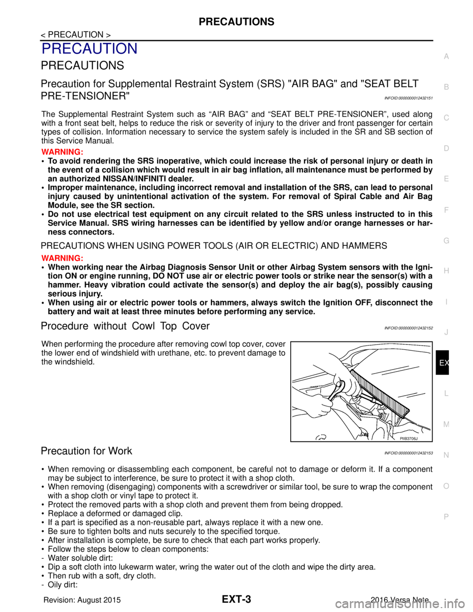
When performing the procedure after removing cowl top cover, cover
the lower end of windshield with urethane, etc. to prevent damage to
the windshield.
Precaution for WorkINFOID:0000000012432153
• When removing or disassembling each component, be ca reful not to damage or deform it. If a component
may be subject to interference, be sure to protect it with a shop cloth.
• When removing (disengaging) components with a screwdriver or similar tool, be sure to wrap the component with a shop cloth or vinyl tape to protect it.
• Protect the removed parts with a shop cloth and prevent them from being dropped.
• Replace a deformed or damaged clip.
• If a part is specified as a non-reusabl e part, always replace it with a new one.
• Be sure to tighten bolts and nuts securely to the specified torque.
• After installation is complete, be sure to check that each part works properly.
• Follow the steps below to clean components:
- Water soluble dirt:
• Dip a soft cloth into lukewarm water, wring the water out of the cloth and wipe the dirty area.
• Then rub with a soft, dry cloth.
-Oily dirt:
PIIB3706J
Revision: August 2015 2016 Versa Note
cardiagn.com
Page 1791 of 3641

EXT-24
< REMOVAL AND INSTALLATION >
FRONT BUMPER
TYPE 2
Removal and InstallationINFOID:0000000012432166
CAUTION:
Bumper fascia is made of resin. Use care when handling to prevent damage. Avoid contact with oily
substances.
REMOVAL
1. Remove the front grille. Refer to EXT-32, "Removal and Installation".
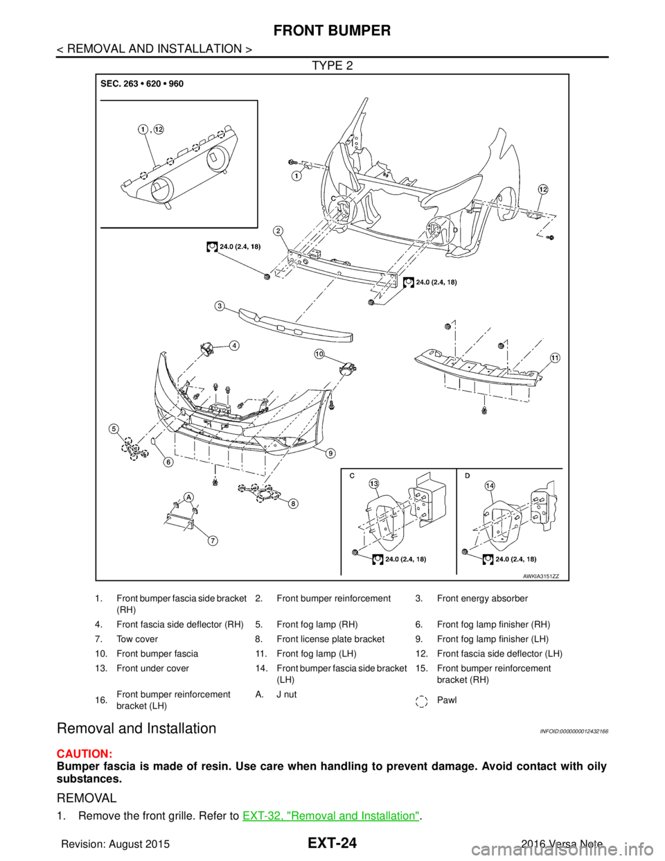
AWKIA3151ZZ
1. Front bumper fascia side bracket
(RH) 2. Front bumper reinforcement 3. Front energy absorber
4. Front fascia side deflector (RH) 5. Front fog lamp (RH) 6. Front fog lamp finisher (RH)
7. Tow cover 8. Front license plate bracket 9. Front fog lamp finisher (LH)
10. Front bumper fascia 11. Front fog lamp (LH)12. Front fascia side deflector (LH)
13. Front under cover 14. Front bumper fascia side bracket
(LH) 15. Front bumper reinforcement
bracket (RH)
16. Front bumper reinforcement
bracket (LH) A. J nut
Pawl
Revision: August 2015 2016 Versa Note
cardiagn.com
Page 1796 of 3641

REAR BUMPEREXT-29
< REMOVAL AND INSTALLATION >
C
DE
F
G H
I
J
L
M A
B
EXT
N
O P
TYPE 2
Removal and InstallationINFOID:0000000012432168
CAUTION:
Bumper fascia is made of resin. Use care when handling to prevent damage. Avoid contact with oily
substances.
REMOVAL
1. Remove rear combination lamps (LH/RH). Refer to EXL-109, "Removal and Installation".
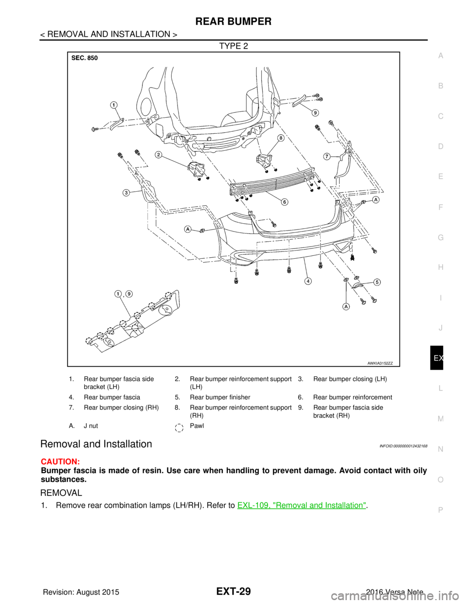
AWKIA3152ZZ
1. Rear bumper fascia side
bracket (LH) 2. Rear bumper reinforcement support
(LH) 3. Rear bumper closing (LH)
4. Rear bumper fascia 5. Rear bumper finisher 6. Rear bumper reinforcement
7. Rear bumper closing (RH) 8. Rear bumper reinforcement support (RH)9. Rear bumper fascia side
bracket (RH)
A. J nut Pawl
Revision: August 2015 2016 Versa Note
cardiagn.com