2016 NISSAN NOTE oil type
[x] Cancel search: oil typePage 2326 of 3641

RECOMMENDED FLUIDS AND LUBRICANTSMA-11
< PERIODIC MAINTENANCE >
C
DE
F
G H
I
J
K L
M B
MA
N
O A
RECOMMENDED FLUIDS AND LUBRICANTS
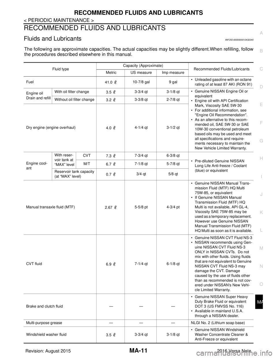
Fluids and LubricantsINFOID:0000000012432245
The following are approximate capacities. The actual capa
cities may be slightly different.When refilling, follow
the procedures described elsewhere in this manual.
Fluid type Capacity (Approximate)
Recommended Fluids/Lubricants
Metric US measure Imp measure
Fuel 41.0 10-7/8 gal
9 gal• Unleaded gasoline with an octane
rating of at least 87 AKI (RON 91)
Engine oil
Drain and refill With oil filter change
3.5 3-3/4 qt 3-1/8 qt
• Genuine NISSAN Engine Oil or
equivalent
• Engine oil with API Certification
Mark, Viscosity SAE 5W-30
• For additional information, see "Engine Oil Recommendation".
• As an alternative to this recom-
mended oil, SAE 5W-30 or SAE
10W-30 conventional petroleum
based oils may be used and meet
all specifications and require-
ments necessary to maintain the
New Vehicle Limited Warranty.
Without oil filter change
3.2 3-3/8 qt 2-7/8 qt
Dry engine (engine overhaul) 4.0 4-1/4 qt 3-1/2 qt
Engine cool-
ant With reser-
voir tank at
“MAX” level
CVT
7.3 7-3/4 qt 6-3/8 qt
• Pre-diluted Genuine NISSAN Long Life Anti-freeze / Coolant
(blue) or equivalent
M/T
6.7 7-1/8 qt 5-7/8 qt
Reservoir tank capacity
(at “MAX” level) 0.7
3/4 qt
5/8 qt
Manual transaxle fluid (MTF) 2.67 5-5/8 pt 4-3/4 pt • Genuine NISSAN
Manual Trans-
mission Fluid (MTF) HQ Multi
75W-85, or equivalent
• If Genuine NISSAN Manual
Transmission Fluid (MTF) HQ
Multi is not available, API GL-4,
Viscosity SAE 75W-85 may be
used as a temporary replacement.
However use Genuine NISSAN
Manual Transmission Fluid (MTF)
HQ Multi as soon as it is available.
CVT fluid 6.9 7-1/4 qt 6-1/8 qt • Genuine NISSAN CVT Fluid NS-3
• NISSAN recommends using Gen-
uine NISSAN CVT Fluid NS-3
ONLY in NISSAN CVTs. Do not
mix with other fluids. Using fluids
that are not equivalent to Genuine
NISSAN CVT Fluid NS-3 may
damage the CVT. Damage
caused by the use of fluids other
than as recommended is not cov-
ered under NISSAN's New Vehi-
cle Limited Warranty.
Brake and clutch fluid —— —• Genuine NISSAN Super Heavy
Duty Brake Fluid or equivalent
DOT 3 (US FMVSS No. 116)
• Available in mainland U.S.A.
through a NISSAN dealer.
Multi-purpose grease —— — NLGI No. 2 (Lithium soap base)
Windshield washer fluid 3.5 3-3/4 qt 3-1/8 qt • Genuine NISSAN Windshield
Washer Concentrate Cleaner &
Anti-Freeze or equivalent
Revision: August 2015 2016 Versa Note
cardiagn.com
Page 2327 of 3641

MA-12
< PERIODIC MAINTENANCE >
RECOMMENDED FLUIDS AND LUBRICANTS
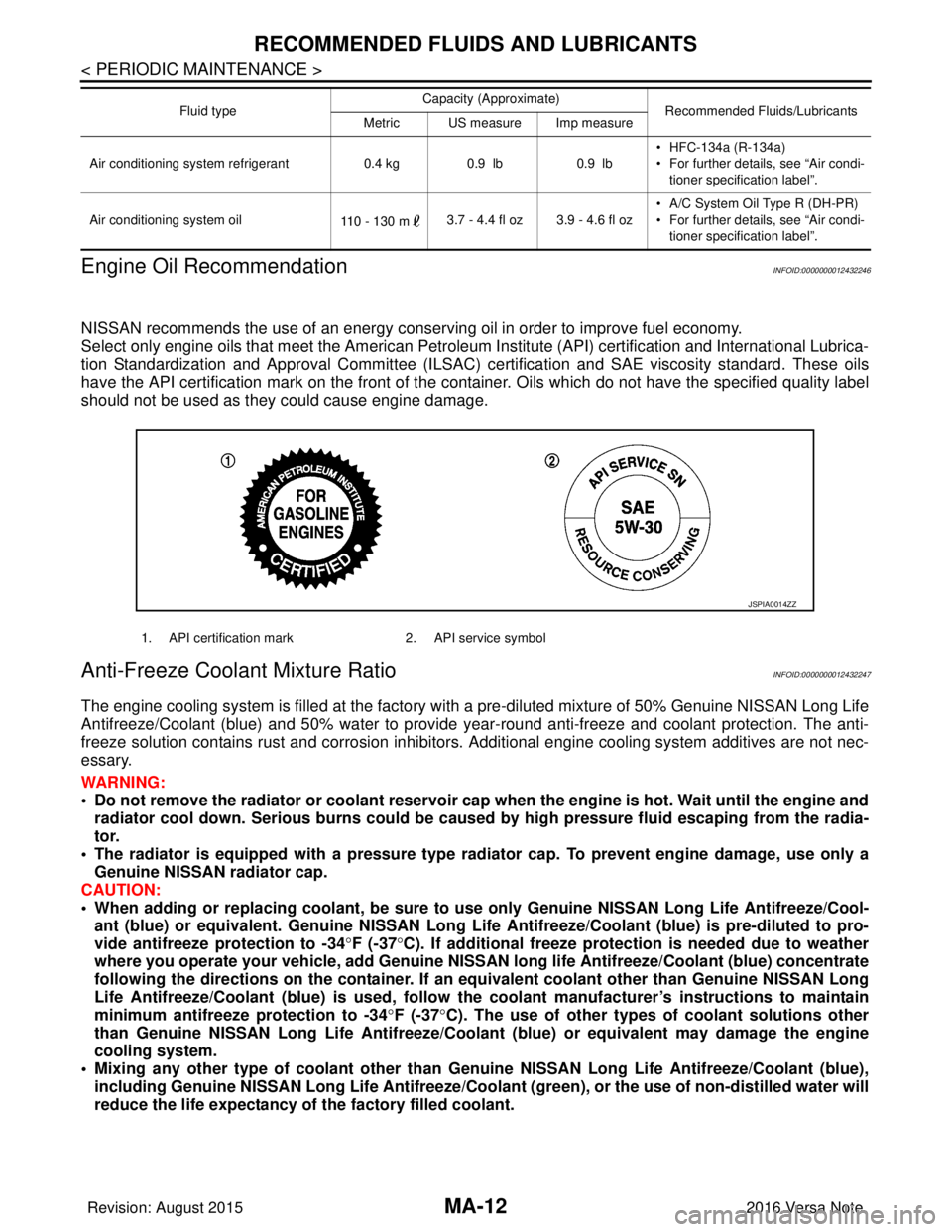
Engine Oil Recommendation
INFOID:0000000012432246
NISSAN recommends the use of an energy conservi ng oil in order to improve fuel economy.
Select only engine oils that meet the American Petroleum Institute (API) certification and International Lubrica-
tion Standardization and Approval Committee (ILSAC) ce rtification and SAE viscosity standard. These oils
have the API certification mark on the front of the container. Oils whic h do not have the specified quality label
should not be used as they could cause engine damage.
Anti-Freeze Coolant Mixture RatioINFOID:0000000012432247
The engine cooling system is filled at the factory with a pre-diluted mixture of 50% Genuine NISSAN Long Life
Antifreeze/Coolant (blue) and 50% water to provide year-round anti-freeze and coolant protection. The anti-
freeze solution contains rust and corrosion inhibitors. Additional engine cooling system additives are not nec-
essary.
WARNING:
• Do not remove the radiator or coolant reservoir cap when the engine is hot. Wait until the engine and radiator cool down. Serious burns could be caused by high pressure fluid escaping from the radia-
tor.
• The radiator is equipped with a pressure type radiator cap. To prevent engine damage, use only a
Genuine NISSAN radiator cap.
CAUTION:
• When adding or replacing coolant, be sure to use only Genuine NISSAN Lo ng Life Antifreeze/Cool-
ant (blue) or equivalent. Genuine NISSAN Long Life Antifreeze/Coolant (blue) is pre-diluted to pro-
vide antifreeze protection to -34 °F (-37 °C). If additional freeze protect ion is needed due to weather
where you operate your vehicle, add Genuine NISSAN long life Antifreeze/Coolant (blue) concentrate
following the directions on the container. If an equivalent coolant other than Genuine NISSAN Long
Life Antifreeze/Coolant (blue) is used, follow the coolant manufact urer’s instructions to maintain
minimum antifreeze protection to -34 °F (-37 °C). The use of other types of coolant solutions other
than Genuine NISSAN Long Life Antifreeze/Coolant (blue) or equivalent may damage the engine
cooling system.
• Mixing any other type of coolant other than Genuine NISSAN Long Life Antifreeze/Coolant (blue),
including Genuine NISSAN Long Life Antifreeze/Coolant (green), or the use of non-distilled water will
reduce the life expectancy of the factory filled coolant.
Air conditioning system refrigerant 0.4 kg0.9 lb 0.9 lb• HFC-134a (R-134a)
• For further details, see “Air condi-
tioner specification label”.
Air conditioning system oil 110 - 130 m3.7 - 4.4 fl oz 3.9 - 4.6 fl oz • A/C System Oil Type R (DH-PR)
• For further details, see “Air condi-
tioner specification label”.
Fluid type
Capacity (Approximate)
Recommended Fluids/Lubricants
Metric US measure Imp measure
1. API certification mark 2. API service symbol
JSPIA0014ZZ
Revision: August 2015 2016 Versa Note
cardiagn.com
Page 2347 of 3641

MA-32
< PERIODIC MAINTENANCE >
CHASSIS AND BODY MAINTENANCE
GEAR OIL : Refilling
INFOID:0000000012432275
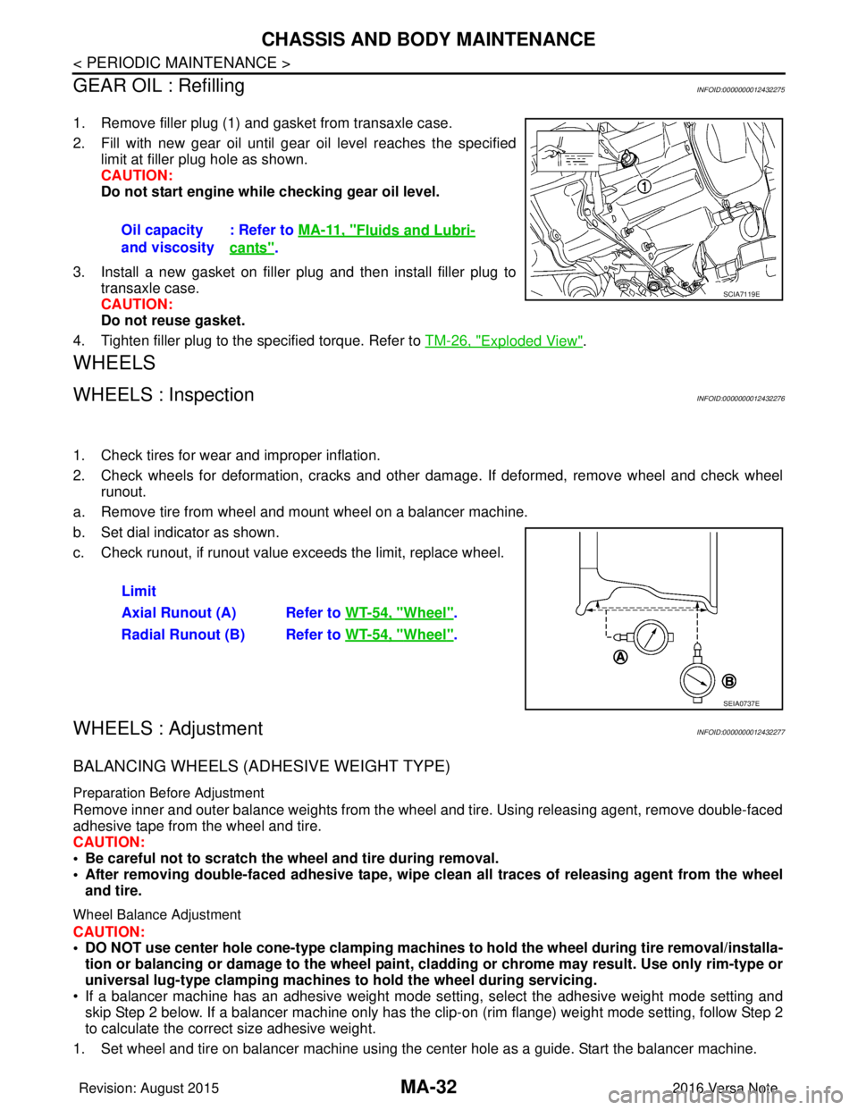
1. Remove filler plug (1) and gasket from transaxle case.
2. Fill with new gear oil until gear oil level reaches the specified limit at filler plug hole as shown.
CAUTION:
Do not start engine whil e checking gear oil level.
3. Install a new gasket on filler plug and then install filler plug to transaxle case.
CAUTION:
Do not reuse gasket.
4. Tighten filler plug to the specified torque. Refer to TM-26, "
Exploded View".
WHEELS
WHEELS : InspectionINFOID:0000000012432276
1. Check tires for wear and improper inflation.
2. Check wheels for deformation, cracks and other dam age. If deformed, remove wheel and check wheel
runout.
a. Remove tire from wheel and mount wheel on a balancer machine.
b. Set dial indicator as shown.
c. Check runout, if runout value exceeds the limit, replace wheel.
WHEELS : AdjustmentINFOID:0000000012432277
BALANCING WHEELS (ADHESIVE WEIGHT TYPE)
Preparation Before Adjustment
Remove inner and outer balance weights from the wheel and tire. Using releasing agent, remove double-faced
adhesive tape from the wheel and tire.
CAUTION:
• Be careful not to scratch the wheel and tire during removal.
• After removing double-faced adh esive tape, wipe clean all traces of releasing agent from the wheel
and tire.
Wheel Balance Adjustment
CAUTION:
• DO NOT use center hole cone-type clamping machines to hold the wheel during tire removal/installa-
tion or balancing or damage to the wheel paint, cladding or chrome may result. Use only rim-type or
universal lug-type clamping machines to hold the wheel during servicing.
• If a balancer machine has an adhesive weight mode se tting, select the adhesive weight mode setting and
skip Step 2 below. If a balancer machine only has the clip -on (rim flange) weight mode setting, follow Step 2
to calculate the correct size adhesive weight.
1. Set wheel and tire on balancer machine using the center hole as a guide. Start the balancer machine. Oil capacity
and viscosity
: Refer to
MA-11, "
Fluids and Lubri-
cants".
SCIA7119E
Limit
Axial Runout (A) Refer to WT-54, "
Wheel".
Radial Runout (B) Refer to WT-54, "
Wheel".
SEIA0737E
Revision: August 2015 2016 Versa Note
cardiagn.com
Page 2359 of 3641

MWI
MWI-1
DRIVER INFORMATION & MULTIMEDIA
C
DE
F
G H
I
J
K L
M B
SECTION MWI
A
O P
CONTENTS
METER, WARNING LAMP & INDICATOR
TYPE A
HOW TO USE THIS MANU AL ......................
5
APPLICATION NOTICE ................................. .....5
Information .......................................................... ......5
PRECAUTION ...............................................6
PRECAUTIONS .............................................. .....6
Precaution for Supplemental Restraint System
(SRS) "AIR BAG" and "SEAT BELT PRE-TEN-
SIONER" ............................................................. ......
6
PREPARATION ............................................7
PREPARATION .............................................. .....7
Commercial Service Tools .................................. ......7
SYSTEM DESCRIPTION ..............................8
COMPONENT PARTS ................................... .....8
METER SYSTEM .........................................................8
METER SYSTEM : Compo nent Parts Location ........8
METER SYSTEM : Combinat ion Meter ....................9
SYSTEM ......................................................... ....10
METER SYSTEM .......................................................10
METER SYSTEM : System Description ..................10
METER SYSTEM : Fail-safe ...................................11
SPEEDOMETER ................ ........................................12
SPEEDOMETER : System Description ............... ....12
TACHOMETER ...................................................... ....12
TACHOMETER : System Description .....................12
SHIFT POSITION INDICATOR .............................. ....12
SHIFT POSITION INDICATOR : System Descrip-
tion ...................................................................... ....
13
OIL PRESSURE WARNING LAMP ...........................13
OIL PRESSURE WARNING LAMP : System De-
scription ............................................................... ....
13
METER ILLUMINATION CONTROL ..................... ....13
METER ILLUMINATION CONTROL : System De-
scription ...................................................................
13
INFORMATION DISPLAY ...................................... ....14
INFORMATION DISPLAY : System Description .....14
OPERATION .....................................................16
Switch Name and Function ......................................16
DIAGNOSIS SYSTEM (COMBINATION
METER) .............................................................
17
On Board Diagnosis Function ..................................17
CONSULT Function (METER/M&A) ........................18
ECU DIAGNOSIS INFORMATION ..............21
COMBINATION METER ...................................21
Reference Value .................................................. ....21
Fail-safe ...................................................................23
DTC Index ...............................................................24
BCM (BODY CONTROL MODULE) .................25
List of ECU Reference .............................................25
WIRING DIAGRAM ......................................26
METER SYSTEM ..............................................26
Wiring Diagram .................................................... ....26
BASIC INSPECTION ...................................37
DIAGNOSIS AND REPAIR WORK FLOW .......37
Work Flow ............................................................ ....37
DTC/CIRCUIT DIAGNOSIS .........................38
U1000 CAN COMM CIRCUIT ...........................38
DTC Logic ............................................................ ....38
Diagnosis Procedure ..............................................38
Revision: August 2015 2016 Versa Note
cardiagn.com
Page 2360 of 3641

MWI-2
U1010 CONTROL UNIT (CAN) .........................39
Description ........................................................... ...39
DTC Logic ...............................................................39
Diagnosis Procedure ..............................................39
B2205 VEHICLE SPEED ...................................40
Description ........................................................... ...40
DTC Logic ...............................................................40
Diagnosis Procedure .............................................40
B2267 ENGINE SPEED .....................................41
Description ........................................................... ...41
DTC Logic ...............................................................41
Diagnosis Procedure ..............................................41
B2268 WATER TEMP ........................................42
Description ........................................................... ...42
DTC Logic ...............................................................42
Diagnosis Procedure ..............................................42
POWER SUPPLY AND GROUND CIRCUIT .....43
COMBINATION METER ........................................ ...43
COMBINATION METER : Diagnosis Procedure ....43
BCM (BODY CONTROL MODULE) ...................... ...43
BCM (BODY CONTROL MODULE) : Diagnosis
Procedure ...............................................................
44
FUEL LEVEL SENSOR SIGNAL CIRCUIT .......45
Description ........................................................... ...45
Component Function Check ...................................45
Diagnosis Procedure .............................................45
Component Inspection ............................................46
WASHER FLUID LEVEL SWITCH CIRCUIT ....47
Description ........................................................... ...47
Diagnosis Procedure ..............................................47
Component Inspection ............................................47
SYMPTOM DIAGNOSIS .............................48
THE FUEL GAUGE INDICATOR DOES NOT
OPERATE ....................................................... ...
48
Description ........................................................... ...48
Diagnosis Procedure ..............................................48
THE OIL PRESSURE WARNING LAMP
DOES NOT TURN ON .......................................
49
Description ..............................................................49
Diagnosis Procedure ..............................................49
THE OIL PRESSURE WARNING LAMP
DOES NOT TURN OFF .....................................
50
Description ........................................................... ...50
Diagnosis Procedure ..............................................50
THE DOOR OPEN WARNING CONTINUES
DISPLAYING, OR DOES NOT DISPLAY ..........
51
Description ........................................................... ...51
Diagnosis Procedure ..............................................51
THE PARKING BRAKE RELEASE WARNING
CONTINUES DISPLAYING, OR DOES NOT
DISPLAY ............................................................
52
Description ........................................................... ...52
Diagnosis Procedure ...............................................52
THE LOW WASHER FLUID WARNING CON-
TINUES DISPLAYING, or DOES NOT DIS-
PLAY ..................................................................
53
Description ........................................................... ...53
Diagnosis Procedure ...............................................53
REMOVAL AND INSTALLATION ..............54
COMBINATION METER ................................. ...54
Removal and Installation .........................................54
TYPE B
HOW TO USE THIS MANU AL ...................
55
APPLICATION NOTICE ................................. ...55
Information ........................................................... ...55
PRECAUTION ............................................56
PRECAUTIONS .............................................. ...56
Precaution for Supplemental Restraint System
(SRS) "AIR BAG" and "SEAT BELT PRE-TEN-
SIONER" .............................................................. ...
56
PREPARATION ..........................................57
PREPARATION .............................................. ...57
Commercial Service Tools ................................... ...57
SYSTEM DESCRIPTION ...........................58
COMPONENT PARTS .................................... ...58
METER SYSTEM .......................................................58
METER SYSTEM : Component Parts Location ... ...58
METER SYSTEM : Combination Meter ..................59
SYSTEM ............................................................61
METER SYSTEM .......................................................61
METER SYSTEM : System Description ............... ...61
METER SYSTEM : Fail-safe ...................................62
SPEEDOMETER .................................................... ...63
SPEEDOMETER : System Description ..................63
TACHOMETER ....................................................... ...63
TACHOMETER : System Description .....................64
SHIFT POSITION INDICATOR .............................. ...64
SHIFT POSITION INDICATOR : System Descrip-
tion ....................................................................... ...
64
HIGH WATER TEMPERATURE WARNING LAMP ...64
HIGH WATER TEMPERATURE WARNING
LAMP : System Description ....................................
64
Revision: August 2015 2016 Versa Note
cardiagn.com
Page 2366 of 3641
![NISSAN NOTE 2016 Service Repair Manual MWI-8
< SYSTEM DESCRIPTION >[TYPE A]
COMPONENT PARTS
SYSTEM DESCRIPTION
COMPONENT PARTS
METER SYSTEM
METER SYSTEM : Component Parts LocationINFOID:0000000012432541
A. Combination meter
B. View with re NISSAN NOTE 2016 Service Repair Manual MWI-8
< SYSTEM DESCRIPTION >[TYPE A]
COMPONENT PARTS
SYSTEM DESCRIPTION
COMPONENT PARTS
METER SYSTEM
METER SYSTEM : Component Parts LocationINFOID:0000000012432541
A. Combination meter
B. View with re](/manual-img/5/57363/w960_57363-2365.png)
MWI-8
< SYSTEM DESCRIPTION >[TYPE A]
COMPONENT PARTS
SYSTEM DESCRIPTION
COMPONENT PARTS
METER SYSTEM
METER SYSTEM : Component Parts LocationINFOID:0000000012432541
A. Combination meter
B. View with rear lower seat cushion and inspection hole
cover removed.
No. Component Function
1. Parking brake switch Transmits the parking brake switch signal to the combination meter.
2. ABS actuator and electric unit
(control unit) Transmits the vehicle speed signal to the combination meter via CAN communication.
Refer to BRC-7, "
Component Parts Location" for detailed installation location.
3. Washer fluid level switch Transmits the washer fluid level switch signal to the combination meter (for Canada).
Refer to WW-6, "
Component Parts Location" for detailed installation location.
4. Engine oil pressure sensor Transmits the engine oil pressure sensor signal to the ECM.
Refer to EM-93, "
Exploded View" for detailed installation location.
5. TCM Transmits the shift position signal to the combination meter via CAN communication
(with CVT).
Refer to TM-61, "
CVT CONTROL SYSTEM : Co
mponent Parts Location" for detailed
installation location.
AWNIA3135ZZ
Revision: August 2015 2016 Versa Note
cardiagn.com
Page 2367 of 3641
![NISSAN NOTE 2016 Service Repair Manual MWI
COMPONENT PARTSMWI-9
< SYSTEM DESCRIPTION > [TYPE A]
C
D
E
F
G H
I
J
K L
M B A
O P
METER SYSTEM : Combination MeterINFOID:0000000012432542
The combination meter controls the following items a ccor NISSAN NOTE 2016 Service Repair Manual MWI
COMPONENT PARTSMWI-9
< SYSTEM DESCRIPTION > [TYPE A]
C
D
E
F
G H
I
J
K L
M B A
O P
METER SYSTEM : Combination MeterINFOID:0000000012432542
The combination meter controls the following items a ccor](/manual-img/5/57363/w960_57363-2366.png)
MWI
COMPONENT PARTSMWI-9
< SYSTEM DESCRIPTION > [TYPE A]
C
D
E
F
G H
I
J
K L
M B A
O P
METER SYSTEM : Combination MeterINFOID:0000000012432542
The combination meter controls the following items a ccording to the signals received from each unit via CAN
communication and the signals from switches and sensors:
• Measuring instruments
• Indicator lamps
• Warning lamps
• Meter illumination control
• Information display
ARRANGEMENT OF COMBINATION METER
6. ECM Transmits the following signals to the combination meter via CAN communication:
• Engine speed signal
• Engine coolant temperature signal
• Fuel consumption monitor signal
• Engine oil pressure sensor signal
Refer to EC-14, "
ENGINE CONTROL SYSTEM : ComponentPartsLocation" for de-
tailed installation location.
7. BCM Transmits the following signals to the combination meter via CAN communication:
• Door switch signal
• Buzzer signal
Refer to BCS-137, "
Removal and Installation" for detailed installation location.
8. Combination meter Refer to MWI-9, "
METER SYSTEM : Combination Meter".
9. Fuel level sensor unit and fuel pump
(fuel level sensor) Transmits the fuel level sensor signal to the combination meter.
No.
Component Function
U: USAEU: Except USA
AWNIA3633ZZ
Revision: August 2015 2016 Versa Note
cardiagn.com
Page 2368 of 3641
![NISSAN NOTE 2016 Service Repair Manual MWI-10
< SYSTEM DESCRIPTION >[TYPE A]
SYSTEM
SYSTEM
METER SYSTEM
METER SYSTEM : System DescriptionINFOID:0000000012432543
SYSTEM DIAGRAM
COMBINATION METER INPUT SIGNAL (CAN COMMUNICATION SIGNAL)
DESCR NISSAN NOTE 2016 Service Repair Manual MWI-10
< SYSTEM DESCRIPTION >[TYPE A]
SYSTEM
SYSTEM
METER SYSTEM
METER SYSTEM : System DescriptionINFOID:0000000012432543
SYSTEM DIAGRAM
COMBINATION METER INPUT SIGNAL (CAN COMMUNICATION SIGNAL)
DESCR](/manual-img/5/57363/w960_57363-2367.png)
MWI-10
< SYSTEM DESCRIPTION >[TYPE A]
SYSTEM
SYSTEM
METER SYSTEM
METER SYSTEM : System DescriptionINFOID:0000000012432543
SYSTEM DIAGRAM
COMBINATION METER INPUT SIGNAL (CAN COMMUNICATION SIGNAL)
DESCRIPTION
Combination Meter
• The combination meter receives necessary signals from each unit, switch, and sensor to control the follow-
ing functions.
- Measuring instruments
- Warning lamps
- Indicator lamps
- Meter illumination control
- Information display
• The combination meter incorporates a buzzer function that sounds an audible alarm with the integrated buzzer device. Refer to WCS-7, "
WARNING CHIME SYSTEM : System Description" for further details.
AWNIA3080GB
Transmit unit Signal name
ABS actuator and electric unit (c ontrol unit) Vehicle speed signal
BCM Door switch signal
Buzzer signal
TCM Shift position signal
ECM Engine speed signal
Engine coolant temperature signal
Engine oil pressure signal
Fuel consumption signal
Loose fuel cap signal
Revision: August 2015
2016 Versa Note
cardiagn.com