2016 NISSAN NOTE oil type
[x] Cancel search: oil typePage 2029 of 3641
HA-4
< PRECAUTION >
PRECAUTIONS
Precaution for Procedure without Cowl Top Cover
INFOID:0000000012431986
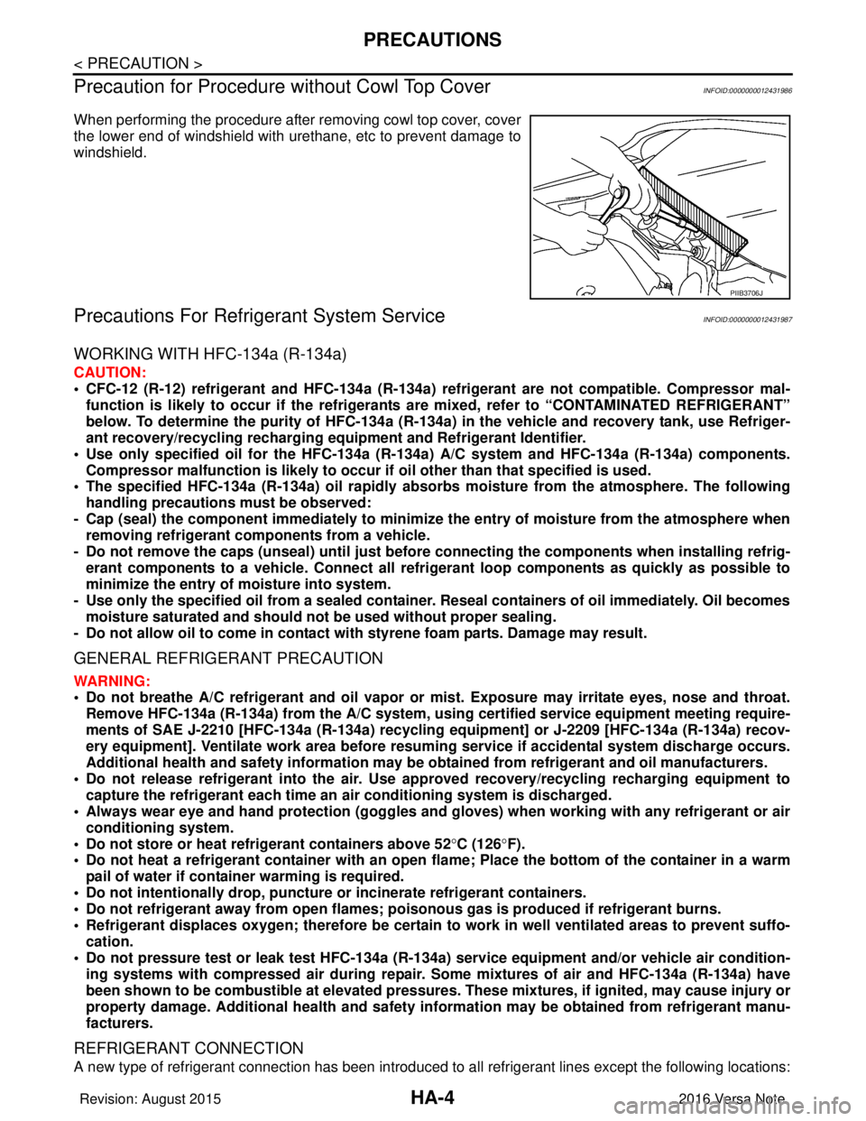
When performing the procedure after removing cowl top cover, cover
the lower end of windshield with urethane, etc to prevent damage to
windshield.
Precautions For Refrigerant System ServiceINFOID:0000000012431987
WORKING WITH HFC-134a (R-134a)
CAUTION:
• CFC-12 (R-12) refrigerant and HFC-134a (R-134a) refrigerant are not compatible. Compressor mal-
function is likely to occur if the refrigerants are mixed, refe r to “CONTAMINATED REFRIGERANT”
below. To determine the purity of HFC-134a (R-134a) in the vehicle and recovery tank, use Refriger-
ant recovery/recycling recharging equi pment and Refrigerant Identifier.
• Use only specified oil for the HFC-134a (R-134a) A/C system and HFC-134a (R-134a) components.
Compressor malfunction is likely to occur if oil other than that specified is used.
• The specified HFC-134a (R-134a) oi l rapidly absorbs moisture from the atmosphere. The following
handling precautions must be observed:
- Cap (seal) the component immediately to minimize the entry of moisture from the atmosphere when removing refrigerant components from a vehicle.
- Do not remove the caps (unseal) unti l just before connecting the components when installing refrig-
erant components to a vehicle. Connect all refr igerant loop components as quickly as possible to
minimize the entry of moisture into system.
- Use only the specified oil from a sealed container. Reseal containers of oil immediately. Oil becomes
moisture saturated and should no t be used without proper sealing.
- Do not allow oil to come in contact with styrene foam parts. Damage may result.
GENERAL REFRIGERANT PRECAUTION
WARNING:
• Do not breathe A/C refrigerant and oil vapor or mist. Exposure may irritate eyes, nose and throat.
Remove HFC-134a (R-134a) from the A/C system, usin g certified service equipment meeting require-
ments of SAE J-2210 [HFC-134a (R-134a) recycling equipment] or J-2209 [HFC-134a (R-134a) recov-
ery equipment]. Ventilate work area before resumi ng service if accidental system discharge occurs.
Additional health and safety in formation may be obtained from refrigerant and oil manufacturers.
• Do not release refrigerant into the air. Use ap proved recovery/recycling recharging equipment to
capture the refrigerant each time an air conditioning system is discharged.
• Always wear eye and hand protection (goggles and gloves) when working with any refrigerant or air
conditioning system.
• Do not store or heat refrigerant containers above 52 °C (126° F).
• Do not heat a refrigerant containe r with an open flame; Place the bottom of the container in a warm
pail of water if container warming is required.
• Do not intentionally drop, puncture or incinerate refrigerant containers.
• Do not refrigerant away from op en flames; poisonous gas is produced if refrigerant burns.
• Refrigerant displaces oxygen; therefore be certain to work in well ventilated areas to prevent suffo- cation.
• Do not pressure test or leak test HFC-134a (R-134a) service equipment and/or vehicle air condition-
ing systems with compressed air during repair. Some mixtures of air and HFC-134a (R-134a) have
been shown to be combustible at elevated pressures. These mixtures, if ignited, may cause injury or
property damage. Additional heal th and safety information may be obtained from refrigerant manu-
facturers.
REFRIGERANT CONNECTION
A new type of refrigerant connection has been introduced to al l refrigerant lines except the following locations:
PIIB3706J
Revision: August 2015 2016 Versa Note
cardiagn.com
Page 2036 of 3641
PREPARATIONHA-11
< PREPARATION >
C
DE
F
G H
J
K L
M A
B
HA
N
O P
Sealant and/or OilINFOID:0000000012431991
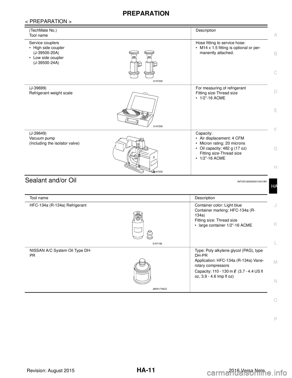
Service couplers
• High side coupler (J-39500-20A)
• Low side coupler
(J-39500-24A) Hose fitting to service hose:
• M14 x 1.5 fitting is optional or per-
manently attached.
(J-39699)
Refrigerant weight scale For measuring of refrigerant
Fitting size-Thread size
• 1/2”-16 ACME
(J-39649)
Vacuum pump
(Including the isolator valve) Capacity:
• Air displacement: 4 CFM
• Micron rating: 20 microns
• Oil capacity: 482 g (17 oz)
Fitting size-Thread size
• 1/2”-16 ACME
(TechMate No.)
Tool name
Description
S-NT202
S-NT200
S-NT203
Tool name
Description
HFC-134a (R-134a) Refrigerant Container color: Light blue
Container marking: HFC-134a (R-
134a)
Fitting size: Thread size
• large container 1/2”-16 ACME
NISSAN A/C System Oil Type DH-
PR Type: Poly alkylene glycol (PAG), type
DH-PR
Application: HFC-134a (R-134a) Vane-
rotary compressors
Capacity: 110 - 130 m (3.7 - 4.4 US fl
oz, 3.9 - 4.6 Imp fl oz)
S-NT196
JMIIA1759ZZ
Revision: August 2015
2016 Versa Note
cardiagn.com
Page 2047 of 3641
HA-22
< PERIODIC MAINTENANCE >
OIL
OIL
DescriptionINFOID:0000000012432001
MAINTENANCE OF OIL LEVEL
The compressor oil circulates in the system together with the refrigerant. It is necessary to add oil to the com-
pressor when replacing A/C system components or when a large amount of refrigerant leaks from the system.
It is important to always maintain oil level within t he specified level. Otherwise, the following conditions may
occur.
• Insufficient oil amount: Stuck compressor
• Excessive oil amount: Insufficient cooling (caused by insufficient heat exchange)
InspectionINFOID:0000000012432002
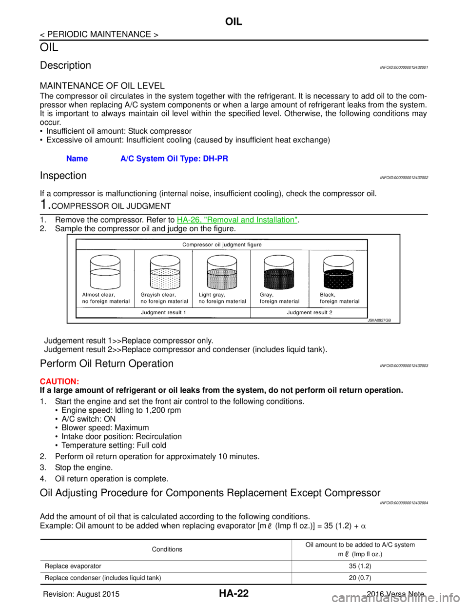
If a compressor is malfunctioning (internal noise, insufficient cooling), check the compressor oil.
1.COMPRESSOR OIL JUDGMENT
1. Remove the compressor. Refer to HA-26, "
Removal and Installation".
2. Sample the compressor oil and judge on the figure.
Judgement result 1>>Replace compressor only.
Judgement result 2>>Replace compressor and condenser (includes liquid tank).
Perform Oil Retu rn OperationINFOID:0000000012432003
CAUTION:
If a large amount of refrigerant or oil leaks from the system, do not perform oil return operation.
1. Start the engine and set the front air control to the following conditions. • Engine speed: Idling to 1,200 rpm
• A/C switch: ON
• Blower speed: Maximum
• Intake door position: Recirculation
• Temperature setting: Full cold
2. Perform oil return operation for approximately 10 minutes.
3. Stop the engine.
4. Oil return operation is complete.
Oil Adjusting Procedure for Compon ents Replacement Except Compressor
INFOID:0000000012432004
Add the amount of oil that is calculated according to the following conditions.
Example: Oil amount to be added when replacing evaporator [m (Imp fl oz.)] = 35 (1.2) + α
Name A/C System Oil Type: DH-PR
JSIIA0927GB
Conditions
Oil amount to be added to A/C system
m (Imp fl oz.)
Replace evaporator 35 (1.2)
Replace condenser (includes liquid tank) 20 (0.7)
Revision: August 20152016 Versa Note
cardiagn.com
Page 2062 of 3641
SERVICE DATA AND SPECIFICATIONS (SDS)HA-37
< SERVICE DATA AND SPECIFICATIONS (SDS)
C
DE
F
G H
J
K L
M A
B
HA
N
O P
SERVICE DATA AND SPECIFICATIONS (SDS)
SERVICE DATA AND SPECIFICATIONS (SDS)
CompressorINFOID:0000000012432023
OilINFOID:0000000012432024
RefrigerantINFOID:0000000012432025
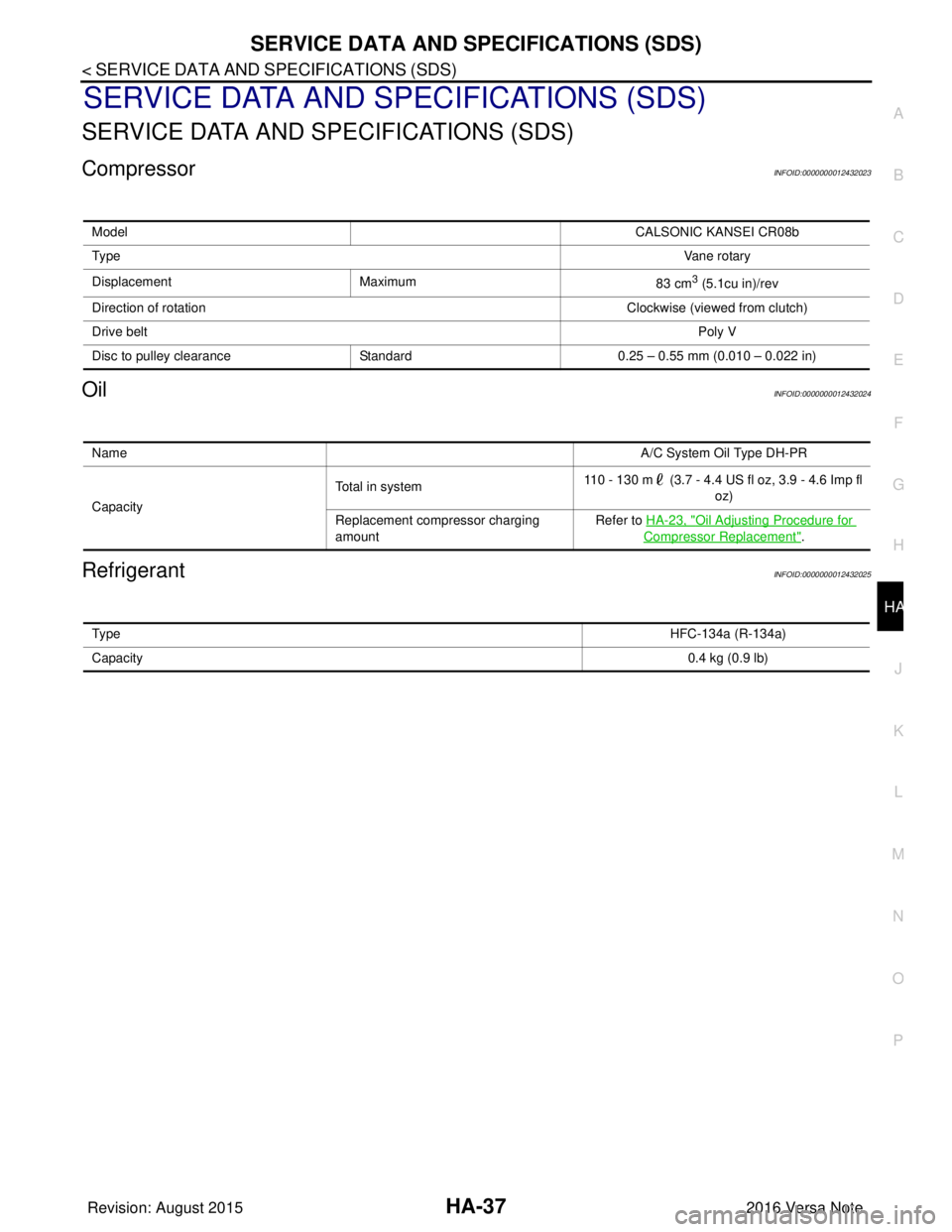
Model CALSONIC KANSEI CR08b
Ty p e Vane rotary
Displacement Maximum 83 cm
3 (5.1cu in)/rev
Direction of rotation Clockwise (viewed from clutch)
Drive belt Poly V
Disc to pulley clearance Standard0.25 – 0.55 mm (0.010 – 0.022 in)
Name A/C System Oil Type DH-PR
Capacity Total in system
110 - 130 m (3.7 - 4.4 US fl oz, 3.9 - 4.6 Imp fl
oz)
Replacement compressor charging
amount Refer to
HA-23, "
Oil Adjusting Procedure for
Compressor Replacement".
Ty p e HFC-134a (R-134a)
Capacity 0.4 kg (0.9 lb)
Revision: August 20152016 Versa Note
cardiagn.com
Page 2070 of 3641

IP-2
< PRECAUTION >
PRECAUTIONS
PRECAUTION
PRECAUTIONS
Precaution for Supplemental Restraint System (SRS) "AIR BAG" and "SEAT BELT
PRE-TENSIONER"
INFOID:0000000012430769
The Supplemental Restraint System such as “A IR BAG” and “SEAT BELT PRE-TENSIONER”, used along
with a front seat belt, helps to reduce the risk or severity of injury to the driver and front passenger for certain
types of collision. Information necessary to service the system safely is included in the SR and SB section of
this Service Manual.
WARNING:
• To avoid rendering the SRS inopera tive, which could increase the risk of personal injury or death in
the event of a collision which would result in air bag inflation, all maintenance must be performed by
an authorized NISSAN/INFINITI dealer.
• Improper maintenance, including in correct removal and installation of the SRS, can lead to personal
injury caused by unintent ional activation of the system. For re moval of Spiral Cable and Air Bag
Module, see the SR section.
• Do not use electrical test equipmen t on any circuit related to the SRS unless instructed to in this
Service Manual. SRS wiring harn esses can be identified by yellow and/or orange harnesses or har-
ness connectors.
PRECAUTIONS WHEN USING POWER TOOLS (AIR OR ELECTRIC) AND HAMMERS
WARNING:
• When working near the Airbag Diagnosis Sensor Unit or other Airbag System sensors with the Igni-
tion ON or engine running, DO NOT use air or electri c power tools or strike near the sensor(s) with a
hammer. Heavy vibration could activate the sensor( s) and deploy the air bag(s), possibly causing
serious injury.
• When using air or electric power tools or hammers , always switch the Ignition OFF, disconnect the
battery and wait at least three minutes before performing any service.
Precaution for WorkINFOID:0000000012430770
• When removing or disassembling each component, be careful not to damage or deform it. If a component may be subject to interference, be sure to protect it with a shop cloth.
• When removing (disengaging) components with a screwdriver or similar tool, be sure to wrap the component with a shop cloth or vinyl tape to protect it.
• Protect the removed parts with a shop cloth and prevent them from being dropped.
• Replace a deformed or damaged clip.
• If a part is specified as a non-reusable part, always replace it with a new one.
• Be sure to tighten bolts and nuts securely to the specified torque.
• After installation is complete, be sure to check that each part works properly.
• Follow the steps below to clean components:
- Water soluble dirt:
• Dip a soft cloth into lukewarm water, wring the water out of the cloth and wipe the dirty area.
• Then rub with a soft, dry cloth.
- Oily dirt:
• Dip a soft cloth into lukewarm water with mild detergent (concentration: within 2 to 3%) and wipe the dirty area.
• Then dip a cloth into fresh water, wring the water out of the cloth and wipe the detergent off.
• Then rub with a soft, dry cloth.
- Do not use organic solvent such as thinner, benzene, alcohol or gasoline.
- For genuine leather seats, use a genuine leather seat cleaner.
Revision: August 2015 2016 Versa Note
cardiagn.com
Page 2097 of 3641
PRECAUTIONSINL-3
< PRECAUTION >
C
DE
F
G H
I
J
K
M A
B
INL
N
O P
PRECAUTION
PRECAUTIONS
Precaution for Supplemental Restraint System (SRS) "AIR BAG" and "SEAT BELT
PRE-TENSIONER"
INFOID:0000000012432718
The Supplemental Restraint System such as “AIR BAG” and “SEAT BELT PRE-TENSIONER”, used along
with a front seat belt, helps to reduce the risk or severi ty of injury to the driver and front passenger for certain
types of collision. Information necessary to service the system safely is included in the SR and SB section of
this Service Manual.
WARNING:
• To avoid rendering the SRS inoper ative, which could increase the risk of personal injury or death in
the event of a collision which would result in air bag inflation, all maintenance must be performed by
an authorized NISSAN/INFINITI dealer.
• Improper maintenance, including in correct removal and installation of the SRS, can lead to personal
injury caused by unintentional act ivation of the system. For removal of Spiral Cable and Air Bag
Module, see the SR section.
• Do not use electrical test equipm ent on any circuit related to the SRS unless instructed to in this
Service Manual. SRS wiring harnesses can be identi fied by yellow and/or orange harnesses or har-
ness connectors.
PRECAUTIONS WHEN USING POWER TOOLS (AIR OR ELECTRIC) AND HAMMERS
WARNING:
• When working near the Airbag Diagnosis Sensor Un it or other Airbag System sensors with the Igni-
tion ON or engine running, DO NOT use air or el ectric power tools or strike near the sensor(s) with a
hammer. Heavy vibration could activate the sensor( s) and deploy the air bag(s), possibly causing
serious injury.
• When using air or electric power tools or hammers, always switch the Ignition OFF, disconnect the
battery and wait at least three mi nutes before performing any service.
Precaution for WorkINFOID:0000000012432719
• When removing or disassembling each component, be ca reful not to damage or deform it. If a component
may be subject to interference, be sure to protect it with a shop cloth.
• When removing (disengaging) components with a screwdriver or similar tool, be sure to wrap the component with a shop cloth or vinyl tape to protect it.
• Protect the removed parts with a shop cloth and prevent them from being dropped.
• Replace a deformed or damaged clip.
• If a part is specified as a non-reusabl e part, always replace it with a new one.
• Be sure to tighten bolts and nuts securely to the specified torque.
• After installation is complete, be sure to check that each part works properly.
• Follow the steps below to clean components:
- Water soluble dirt:
• Dip a soft cloth into lukewarm water, wring the water out of the cloth and wipe the dirty area.
• Then rub with a soft, dry cloth.
-Oily dirt:
• Dip a soft cloth into lukewarm water with mild detergent (concentration: within 2 to 3%) and wipe the dirty
area.
• Then dip a cloth into fresh water, wring the water out of the cloth and wipe the detergent off.
• Then rub with a soft, dry cloth.
- Do not use organic solvent such as thinner, benzene, alcohol or gasoline.
- For genuine leather seats, use a genuine leather seat cleaner.
Revision: August 2015 2016 Versa Note
cardiagn.com
Page 2154 of 3641
PRECAUTIONSINT-3
< PRECAUTION >
C
DE
F
G H
I
K L
M A
B
INT
N
O P
PRECAUTION
PRECAUTIONS
Precaution for Supplemental Restraint System (SRS) "AIR BAG" and "SEAT BELT
PRE-TENSIONER"
INFOID:0000000012431852
The Supplemental Restraint System such as “AIR BAG” and “SEAT BELT PRE-TENSIONER”, used along
with a front seat belt, helps to reduce the risk or severi ty of injury to the driver and front passenger for certain
types of collision. Information necessary to service the system safely is included in the SR and SB section of
this Service Manual.
WARNING:
• To avoid rendering the SRS inoper ative, which could increase the risk of personal injury or death in
the event of a collision which would result in air bag inflation, all maintenance must be performed by
an authorized NISSAN/INFINITI dealer.
• Improper maintenance, including in correct removal and installation of the SRS, can lead to personal
injury caused by unintentional act ivation of the system. For removal of Spiral Cable and Air Bag
Module, see the SR section.
• Do not use electrical test equipm ent on any circuit related to the SRS unless instructed to in this
Service Manual. SRS wiring harnesses can be identi fied by yellow and/or orange harnesses or har-
ness connectors.
PRECAUTIONS WHEN USING POWER TOOLS (AIR OR ELECTRIC) AND HAMMERS
WARNING:
• When working near the Airbag Diagnosis Sensor Un it or other Airbag System sensors with the Igni-
tion ON or engine running, DO NOT use air or el ectric power tools or strike near the sensor(s) with a
hammer. Heavy vibration could activate the sensor( s) and deploy the air bag(s), possibly causing
serious injury.
• When using air or electric power tools or hammers, always switch the Ignition OFF, disconnect the
battery and wait at least three mi nutes before performing any service.
Precaution for WorkINFOID:0000000012431853
• When removing or disassembling each component, be ca reful not to damage or deform it. If a component
may be subject to interference, be sure to protect it with a shop cloth.
• When removing (disengaging) components with a screwdriver or similar tool, be sure to wrap the component with a shop cloth or vinyl tape to protect it.
• Protect the removed parts with a shop cloth and prevent them from being dropped.
• Replace a deformed or damaged clip.
• If a part is specified as a non-reusabl e part, always replace it with a new one.
• Be sure to tighten bolts and nuts securely to the specified torque.
• After installation is complete, be sure to check that each part works properly.
• Follow the steps below to clean components:
- Water soluble dirt:
• Dip a soft cloth into lukewarm water, wring the water out of the cloth and wipe the dirty area.
• Then rub with a soft, dry cloth.
-Oily dirt:
• Dip a soft cloth into lukewarm water with mild detergent (concentration: within 2 to 3%) and wipe the dirty
area.
• Then dip a cloth into fresh water, wring the water out of the cloth and wipe the detergent off.
• Then rub with a soft, dry cloth.
- Do not use organic solvent such as thinner, benzene, alcohol or gasoline.
- For genuine leather seats, use a genuine leather seat cleaner.
Revision: August 2015 2016 Versa Note
cardiagn.com
Page 2323 of 3641
MA-8
< PERIODIC MAINTENANCE >
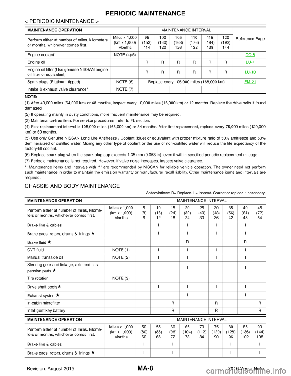
PERIODIC MAINTENANCE
NOTE:
(1) After 40,000 miles (64,000 km) or 48 months, inspect every 10,000 miles (16,000 km) or 12 months. Replace the drive belts if found
damaged.
(2) If operating mainly in dusty conditions, more frequent maintenance may be required.
(3) Maintenance-free item. For service procedures, refer to FL section.
(4) First replacement interval is 105,000 miles (168,000 km) or 84 months. After first replacement, replace every 75,000 miles (120,000
km) or 60 months.
(5) Use only Genuine NISSAN Long Life Antifreeze / Coolant (blue) or equivalent with proper mixture ratio of 50% antifreeze and 50%
demineralized or distilled water. Mixing any other type of coolant or the use of non-distilled water will reduce the life expec tancy of the
factory-fill coolant.
(6) Replace spark plug when the spark plug gap exceeds 1.35 mm (0.053 in), even if within specified periodic replacement mileag e.
(7) Periodic maintenance is not required. However, if valve noise increases, inspect valve clearance.
*: Maintenance items and intervals with “*” are recommended by NISSAN for reli able vehicle operation. The owner need not perform
such maintenance in order to maintain the emission warranty or manufacturer recall liability. Other maintenance items and inter vals are
required.
CHASSIS AND BODY MAINTENANCE
Abbreviations: R= Replace. I = Inspec t. Correct or replace if necessary.
Engine coolant* NOTE (4)(5) CO-8
Engine oil RRRRRRLU-7
Engine oil filter (Use genuine NISSAN engine
oil filter or equivalent) RRRRRR
LU-10
Spark plugs (Platinum-tipped)NOTE (6) Replace every 105,000 miles (168,000 km) EM-21
Intake & exhaust valve clearance*NOTE (7)
MAINTENANCE OPERATION
MAINTENANCE INTERVAL
Reference Page
Perform either at number of miles, kilometers
or months, whichever comes first. Miles x 1,000
(km x 1,000)
Months 95
(152)
11 4 100
(160)
120 105
(168)
126 11 0
(176)
132 11 5
(184)
138 120
(192)
144
MAINTENANCE OPERATION MAINTENANCE INTERVAL
Perform either at number of miles, kilome-
ters or months, whichever comes first. Miles x 1,000
(km x 1,000)
Months 5
(8)
6 10
(16)
12 15
(24)
18 20
(32)
24 25
(40)
30 30
(48)
36 35
(56)
42 40
(64)
48 45
(72)
54
Brake line & cables IIII
Brake pads, rotors, drums & linings IIII
Brake fluid RR
CVT fluid NOTE (1)IIII
Manual transaxle oil NOTE (2)IIII
Steering gear and linkage, axle and sus-
pension parts II
Tire rotation NOTE (3)
Drive shaft boots IIII
Exhaust system II
In-cabin microfilter RRR
Intelligent key battery RRR
MAINTENANCE OPERATION MAINTENANCE INTERVAL
Perform either at number of miles, kilome-
ters or months, whichever comes first. Miles x 1,000
(km x 1,000) Months 50
(80) 60 55
(88) 66 60
(96) 72 65
(104) 78 70
(112) 84 75
(120) 90 80
(128) 96 85
(136) 102 90
(144) 108
Brake line & cables III II
Brake pads, rotors, drums & linings IIIII
Revision: August 2015
2016 Versa Note
cardiagn.com