2016 NISSAN NOTE warning
[x] Cancel search: warningPage 1916 of 3641
GI-28
< PRECAUTION >
LIFTING POINT
LIFTING POINT
Special Service ToolINFOID:0000000012433169
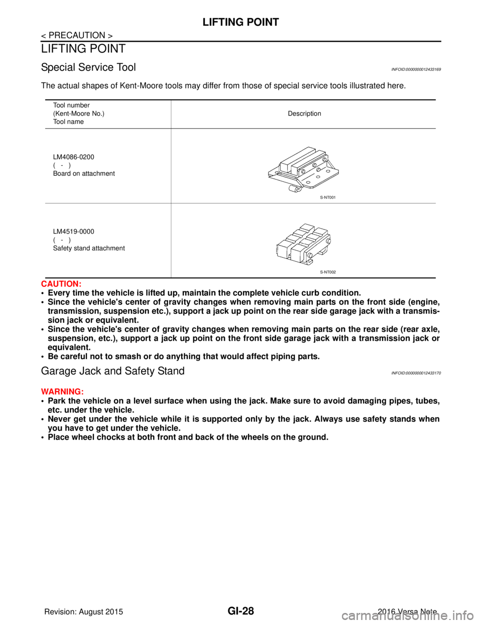
The actual shapes of Kent-Moore tools may differ from those of special service tools illustrated here.
CAUTION:
• Every time the vehicle is lifted up, main tain the complete vehicle curb condition.
• Since the vehicle's center of gravity changes when removing main parts on the front side (engine, transmission, suspension etc.), supp ort a jack up point on the rear side garage jack with a transmis-
sion jack or equivalent.
• Since the vehicle's center of gravity changes when removing main parts on the rear side (rear axle,
suspension, etc.), support a jack up point on the front side garage jack with a transmission jack or
equivalent.
• Be careful not to smash or do anything that would affect piping parts.
Garage Jack and Safety StandINFOID:0000000012433170
WARNING:
• Park the vehicle on a level surface when using the jack. Make sure to avoid damaging pipes, tubes,
etc. under the vehicle.
• Never get under the vehicle while it is supported only by the jack. Always use safety stands when
you have to get under the vehicle.
• Place wheel chocks at both front an d back of the wheels on the ground.
Tool number
(Kent-Moore No.)
Tool name Description
LM4086-0200
( - )
Board on attachment
LM4519-0000
( - )
Safety stand attachment
S-NT001
S-NT002
Revision: August 2015 2016 Versa Note
cardiagn.com
Page 1917 of 3641
LIFTING POINTGI-29
< PRECAUTION >
C
DE
F
G H
I
J
K L
M B
GI
N
O P
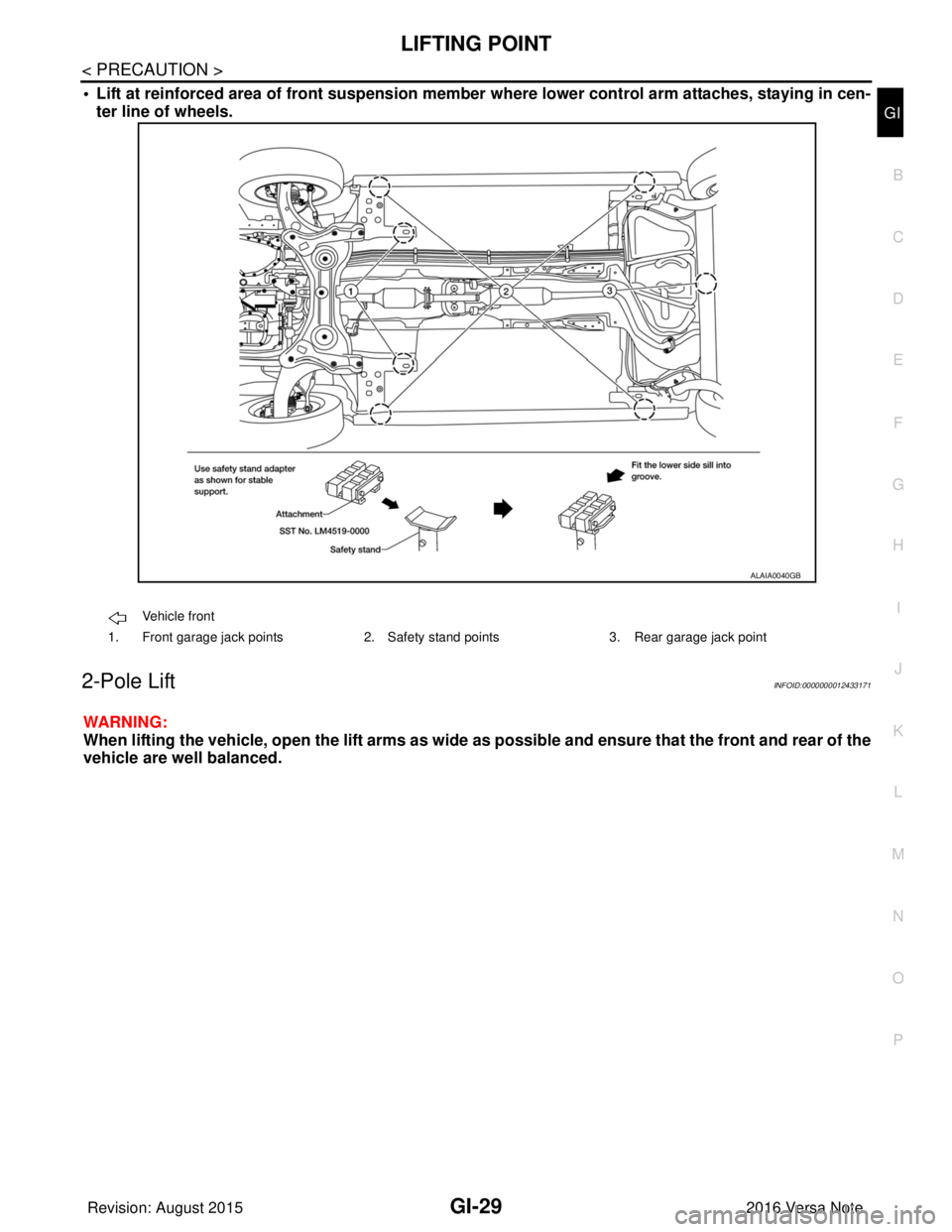
• Lift at reinforced area of front suspension member where lower control arm attaches, staying in cen-
ter line of wheels.
2-Pole LiftINFOID:0000000012433171
WARNING:
When lifting the vehicle, open the lift arms as wide as possible and ensure that the front and rear of the
vehicle are well balanced.
Vehicle front
1. Front garage jack points 2. Safety stand points3. Rear garage jack point
ALAIA0040GB
Revision: August 2015 2016 Versa Note
cardiagn.com
Page 1919 of 3641
TOW TRUCK TOWINGGI-31
< PRECAUTION >
C
DE
F
G H
I
J
K L
M B
GI
N
O PTOW TRUCK TOWING
To w T r u c k To w i n gINFOID:0000000012433173
CAUTION:
• Never tow a CVT model with the rear wheels raised and the front wheels on the ground. This may
cause serious and expensive damage to the transaxle. If it is necessary to tow the vehicle with the
rear wheels raised, always use towin g dollies under the front wheels.
• Never tow a CVT model from the rear (that is b ackward) with four wheels on the ground. This may
cause serious and expensive damage to the transaxle.
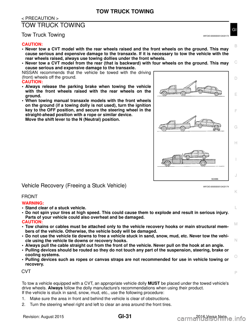
NISSAN recommends that the vehicle be towed with the driving
(front) wheels off the ground.
CAUTION:
• Always release the parking br ake when towing the vehicle
with the front wheels raised with the rear wheels on the
ground.
• When towing manual transaxle models with the front wheels on the ground (if a towing dolly is not used), turn the ignition
key to the OFF position, and secu re the steering wheel in the
straight-ahead position with a rope or similar device.
Move the shift lever to th e N (Neutral) position.
Vehicle Recovery (Freeing a Stuck Vehicle)INFOID:0000000012433174
FRONT
WARNING:
• Stand clear of a stuck vehicle.
• Do not spin your tires at high speed. This could cause them to explode and result in serious injury.
Parts of your vehicle could also overheat and be damaged.
CAUTION:
• Tow chains or cables must be attached only to the vehicle recovery hooks or main structural mem-
bers of the vehicle. Otherwise, the vehicle body will be damaged.
• Do not use the vehicle tie downs to free a vehicle stuck in sand, snow, mud, etc. Never tow the vehi-
cle using the vehicle tie downs or recovery hooks.
• Always pull the cable straight out from the front of the vehicle. Never pull on the hook at an angle.
• Pulling devices should be routed so they do not touch any part of the suspension, steering, brake or
cooling systems.
• Pulling devices such as ropes or canvas straps ar e not recommended for use in vehicle towing or
recovery.
CVT
To tow a vehicle equipped with a CVT, an appropriate vehicle dolly MUST be placed under the towed vehicle's
drive wheels. Always follow the dolly manufacture's re commendations when using their product.
If the vehicle is stuck in sand, snow , mud, etc., use the following procedure:
1. Make sure the area in front and behind the vehicle is clear of obstructions.
2. Turn the steering wheel right and left to clear an area around the front tires.
SGI986
Revision: August 2015 2016 Versa Note
cardiagn.com
Page 1938 of 3641
GI-50
< BASIC INSPECTION >
CONSULT/GST CHECKING SYSTEM
CONSULT/GST CHECKING SYSTEM
DescriptionINFOID:0000000012433188
NOTE:
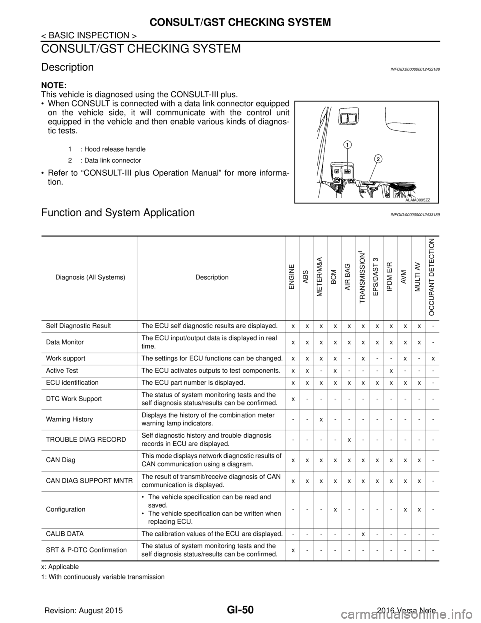
This vehicle is diagnosed using the CONSULT-III plus.
• When CONSULT is connected with a data link connector equippedon the vehicle side, it will communicate with the control unit
equipped in the vehicle and then enable various kinds of diagnos-
tic tests.
• Refer to “CONSULT-III plus Operation Manual” for more informa- tion.
Function and System ApplicationINFOID:0000000012433189
x: Applicable
1: With continuously variable transmission 1 : Hood release handle
2 : Data link connector
ALAIA0095ZZ
Diagnosis (All Systems)
Description
ENGINE
ABS
METER/M&A BCM
AIR BAG
TRANSMISSION
1
EPS/DAST 3 IPDM E/R AV M
MULTI AV
OCCUPANT DETECTION
Self Diagnostic Result The ECU self diagnostic results are displayed. x x x x x x x x x x -
Data Monitor The ECU input/output data is displayed in real
time. xxxxxxxxxx -
Work support The settings for ECU functions can be changed. x x x x - x - - x - x
Active Test The ECU activates outputs to test components. x x - x - - - x - - -
ECU identification The ECU part number is displayed. xxxxxxxxxx -
DTC Work Support The status of system monitoring tests and the
self diagnosis status/results can be confirmed. x----------
Warning History Displays the history of the combination meter
warning lamp indicators.
--x--------
TROUBLE DIAG RECORD Self diagnostic history and trouble diagnosis
records in ECU are displayed. ----x------
CAN Diag This mode displays network diagnostic results of
CAN communication using a diagram. xxxxxxxxxx -
CAN DIAG SUPPORT MNTR The result of transmit/receive diagnosis of CAN
communication is displayed.
xxxxxxxxxx -
Configuration • The vehicle specification can be read and
saved.
• The vehicle specification can be written when
replacing ECU. ---x----xx-
CALIB DATA The calibration values of the ECU are displayed. - - - - - x - - - - -
SRT & P-DTC Confirmation The status of system monitoring tests and the
self diagnosis status/results can be confirmed. x----------
Revision: August 2015
2016 Versa Note
cardiagn.com
Page 1942 of 3641

GW-2
< PRECAUTION >
PRECAUTIONS
PRECAUTION
PRECAUTIONS
Precaution for Supplemental Restraint System (SRS) "AIR BAG" and "SEAT BELT
PRE-TENSIONER"
INFOID:0000000012430522
The Supplemental Restraint System such as “A IR BAG” and “SEAT BELT PRE-TENSIONER”, used along
with a front seat belt, helps to reduce the risk or severity of injury to the driver and front passenger for certain
types of collision. Information necessary to service the system safely is included in the SR and SB section of
this Service Manual.
WARNING:
• To avoid rendering the SRS inopera tive, which could increase the risk of personal injury or death in
the event of a collision which would result in air bag inflation, all maintenance must be performed by
an authorized NISSAN/INFINITI dealer.
• Improper maintenance, including in correct removal and installation of the SRS, can lead to personal
injury caused by unintent ional activation of the system. For re moval of Spiral Cable and Air Bag
Module, see the SR section.
• Do not use electrical test equipmen t on any circuit related to the SRS unless instructed to in this
Service Manual. SRS wiring harn esses can be identified by yellow and/or orange harnesses or har-
ness connectors.
PRECAUTIONS WHEN USING POWER TOOLS (AIR OR ELECTRIC) AND HAMMERS
WARNING:
• When working near the Airbag Diagnosis Sensor Unit or other Airbag System sensors with the Igni-
tion ON or engine running, DO NOT use air or electri c power tools or strike near the sensor(s) with a
hammer. Heavy vibration could activate the sensor( s) and deploy the air bag(s), possibly causing
serious injury.
• When using air or electric power tools or hammers , always switch the Ignition OFF, disconnect the
battery and wait at least three minutes before performing any service.
Handling for Adhe sive and PrimerINFOID:0000000012430523
• Do not use an adhesive which is past its usable date. Shel f life of this product is limited to six months after
the date of manufacture. Carefully adhere to the expiration or manufacture date printed on the box.
• Keep primers and adhesive in a cool, dry place. Ideally, they should be stored in a refrigerator.
• Open the seal of the primer and adhesive just before application. Discard the remainder.
• Before application, be sure to shake the primer container to stir the contents. If any floating material is found,
do not use it.
• If any primer or adhesive contacts the skin, wipe it off with gasoline or equivalent and wash the skin with
soap.
• When using primer and adhesive, always observe the precautions in the instruction manual.
Precaution for WorkINFOID:0000000012430524
• When removing or disassembling each component, be careful not to damage or deform it. If a component
may be subject to interference, be sure to protect it with a shop cloth.
• When removing (disengaging) components with a screwdriver or similar tool, be sure to wrap the component with a shop cloth or vinyl tape to protect it.
• Protect the removed parts with a shop cloth and prevent them from being dropped.
• Replace a deformed or damaged clip.
• If a part is specified as a non-reusable part, always replace it with a new one.
• Be sure to tighten bolts and nuts securely to the specified torque.
• After installation is complete, be sure to check that each part works properly.
• Follow the steps below to clean components:
- Water soluble dirt:
• Dip a soft cloth into lukewarm water, wring the water out of the cloth and wipe the dirty area.
• Then rub with a soft, dry cloth.
- Oily dirt:
• Dip a soft cloth into lukewarm water with mild detergent (concentration: within 2 to 3%) and wipe the dirty area.
Revision: August 2015 2016 Versa Note
cardiagn.com
Page 1952 of 3641
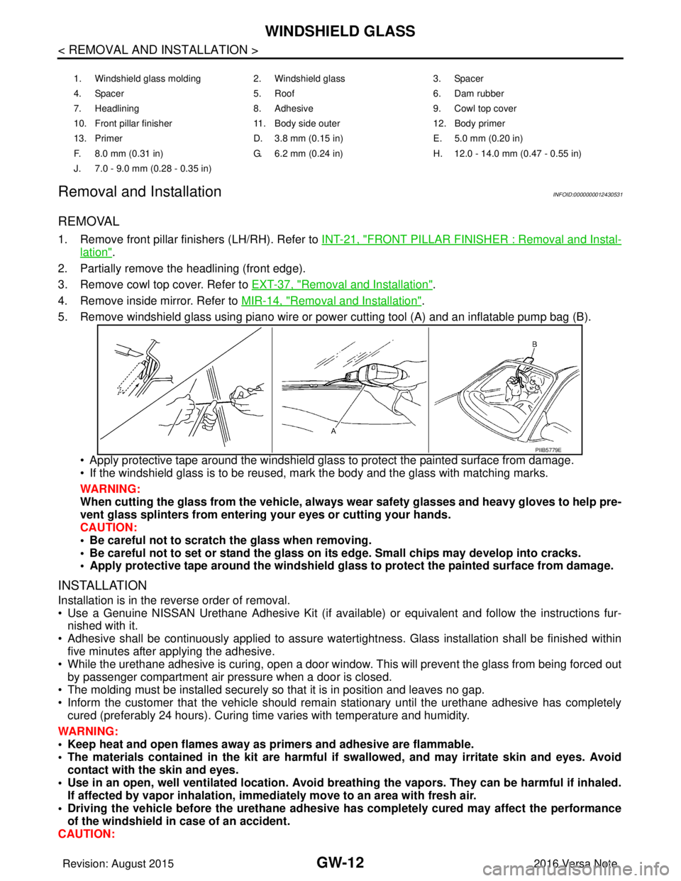
GW-12
< REMOVAL AND INSTALLATION >
WINDSHIELD GLASS
Removal and Installation
INFOID:0000000012430531
REMOVAL
1. Remove front pillar finishers (LH/RH). Refer to INT-21, "FRONT PILLAR FINISHER : Removal and Instal-
lation".
2. Partially remove the headlining (front edge).
3. Remove cowl top cover. Refer to EXT-37, "
Removal and Installation".
4. Remove inside mirror. Refer to MIR-14, "
Removal and Installation".
5. Remove windshield glass using piano wire or pow er cutting tool (A) and an inflatable pump bag (B).
• Apply protective tape around the windshield gla ss to protect the painted surface from damage.
• If the windshield glass is to be reused, mark the body and the glass with matching marks.
WARNING:
When cutting the glass from the vehicle, always wear safety glasses and heavy gloves to help pre-
vent glass splinters from entering your eyes or cutting your hands.
CAUTION:
• Be careful not to scratch the glass when removing.
• Be careful not to set or stand the glass on its edge. Small chips may develop into cracks.
• Apply protective tape around th e windshield glass to protect the painted surface from damage.
INSTALLATION
Installation is in the reverse order of removal.
• Use a Genuine NISSAN Urethane Adhesive Kit (if availabl e) or equivalent and follow the instructions fur-
nished with it.
• Adhesive shall be continuously applied to assure watert ightness. Glass installation shall be finished within
five minutes after applying the adhesive.
• While the urethane adhesive is curing, open a door window . This will prevent the glass from being forced out
by passenger compartment air pressure when a door is closed.
• The molding must be installed securely so that it is in position and leaves no gap.
• Inform the customer that the vehicle should remain stationary until the urethane adhesive has completely
cured (preferably 24 hours). Curing time varies with temperature and humidity.
WARNING:
• Keep heat and open flames away as primers and adhesive are flammable.
• The materials contained in the kit are harmful if swallowed, and may irritate skin and eyes. Avoid
contact with the skin and eyes.
• Use in an open, well ventilated location. Avoid breathing the vapors. They can be harmful if inhaled. If affected by vapor inhalation, imme diately move to an area with fresh air.
• Driving the vehicle before the urethane adhesive has completely cured may affect the performance
of the windshield in case of an accident.
CAUTION:
1. Windshield glass molding 2. Windshield glass 3. Spacer
4. Spacer 5. Roof 6. Dam rubber
7. Headlining 8. Adhesive 9. Cowl top cover
10. Front pillar finisher 11. Body side outer 12. Body primer
13. Primer D. 3.8 mm (0.15 in) E. 5.0 mm (0.20 in)
F. 8.0 mm (0.31 in) G. 6.2 mm (0.24 in) H. 12.0 - 14.0 mm (0.47 - 0.55 in)
J. 7.0 - 9.0 mm (0.28 - 0.35 in)
PIIB5779E
Revision: August 2015 2016 Versa Note
cardiagn.com
Page 1954 of 3641
GW-14
< REMOVAL AND INSTALLATION >
OPERA WINDOW
OPERA WINDOW
Exploded ViewINFOID:0000000012430532
Removal and InstallationINFOID:0000000012430533
REMOVAL
1. Remove front pillar finisher. Refer to INT-21, "FRONT PILLAR FINISHER : Removal and Installation".
2. Remove front fender. Refer to DLK-147, "
Removal and Installation".
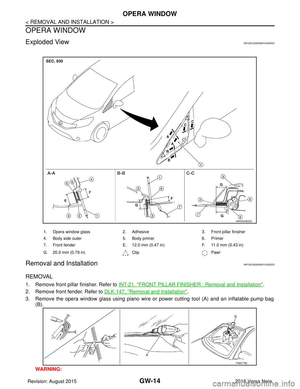
3. Remove the opera window glass using piano wire or power cutting tool (A) and an inflatable pump bag (B).
WARNING:
1. Opera window glass 2. Adhesive3. Front pillar finisher
4. Body side outer 5. Body primer6. Primer
7. Front fender E. 12.0 mm (0.47 in) F. 11.0 mm (0.43 in)
G. 20.0 mm (0.79 in) ClipPawl
AWKIA2460ZZ
PIIB5779E
Revision: August 2015 2016 Versa Note
cardiagn.com
Page 1955 of 3641

OPERA WINDOWGW-15
< REMOVAL AND INSTALLATION >
C
DE
F
G H
I
J
L
M A
B
GW
N
O P
When cutting glass from the vehicle, always wear safety glasses and heavy gloves to prevent
glass splinters from entering your eyes or cutting your hands.
CAUTION:
• Be careful not to scratch the glass when removing.
• Do not set or stand the glass on its ed ge. Small chips may develop into cracks.
• Apply protective tape around the opera windo w glass to protect the painted surface from dam-
age.
INSTALLATION
• Use a Genuine NISSAN Urethane Adhesive Kit (if avail able) or equivalent and follow the instructions fur-
nished with it.
• Adhesive shall be continuously applied to assure watert ightness. Glass installation shall be finished within
five minutes after applying the adhesive.
• The start and finisher of the urethane adhesive applicati on should be located at the bottom to assure water-
tightness.
• While the urethane adhesive is curing, open a door window . This will prevent the glass from being forced out
by passenger compartment air pressure when a door is closed.
• Inform the customer that the vehicle should rema in stationary until the urethane adhesive has completely
cured (preferably 24 hours). Curing time varies with temperature and humidity.
WARNING:
• Keep heat and open flames away as primers and adhesive are flammable.
• The materials contained in the kit are harmful if swallowed, and may irritate skin and eyes. Avoid
contact with skin and eyes.
• Use in an open, well ventilated lo cation. Avoid breathing the vapors. They can be harmful if inhaled.
If affected by vapor inhalation, imme diately move to an area with fresh air.
• Driving the vehicle before the urethane adhesive is completely cured may affect the performance of
the opera window glass in case of an accident.
CAUTION:
• Do not use an adhesive which is past its usable te rm. Shelf life of this product is limited to six
months after the date of manufacture. Carefully ad here to the expiration or manufacture date printed
on the box.
• Keep primers and adhesive in a cool, dry place. Id eally, they should be stored in a refrigerator.
• Do not leave primers or adhesive cartridge unattended with their caps open or off.
• The vehicle should not be driven for at least 24 hours or until the urethane adhesive is completely
cured. Curing time varies depe nding on temperature and humidity. The curing time increases under
lower temperature and lower humidity.
REPAIRING WATER LEAKS FOR OPERA WINDOW GLASS
• Leaks can be repaired without removing and reinstalling opera window glass.
• If water is leaking between the urethane adhesive materi al and body or glass, determine the extent of the
leak.
• This can be done by applying water to the opera window glass area while pushing glass outward.
• To stop the leak, apply primer (if necessary ) and then urethane adhesive to the leak point.
Revision: August 2015 2016 Versa Note
cardiagn.com