Page 1700 of 3641
EXL-48
< WIRING DIAGRAM >
TURN SIGNAL AND HAZARD WARNING LAMP SYSTEM
TURN SIGNAL AND HAZARD WARNING LAMP SYSTEM
Wiring DiagramINFOID:0000000012432796
ABLWA3289GB
Revision: August 2015 2016 Versa Note
cardiagn.com
Page 1701 of 3641
TURN SIGNAL AND HAZARD WARNING LAMP SYSTEMEXL-49
< WIRING DIAGRAM >
C
DE
F
G H
I
J
K
M A
B
EXL
N
O P
ABLIA8115GB
Revision: August 2015 2016 Versa Note
cardiagn.com
Page 1702 of 3641
EXL-50
< WIRING DIAGRAM >
TURN SIGNAL AND HAZARD WARNING LAMP SYSTEM
ABLIA8116GB
Revision: August 20152016 Versa Note
cardiagn.com
Page 1703 of 3641
TURN SIGNAL AND HAZARD WARNING LAMP SYSTEMEXL-51
< WIRING DIAGRAM >
C
DE
F
G H
I
J
K
M A
B
EXL
N
O P
ABLIA8117GB
Revision: August 2015 2016 Versa Note
cardiagn.com
Page 1704 of 3641
EXL-52
< WIRING DIAGRAM >
TURN SIGNAL AND HAZARD WARNING LAMP SYSTEM
ABLIA8118GB
Revision: August 20152016 Versa Note
cardiagn.com
Page 1705 of 3641
TURN SIGNAL AND HAZARD WARNING LAMP SYSTEMEXL-53
< WIRING DIAGRAM >
C
DE
F
G H
I
J
K
M A
B
EXL
N
O P
AALIA2897GB
Revision: August 2015 2016 Versa Note
cardiagn.com
Page 1706 of 3641
EXL-54
< WIRING DIAGRAM >
TURN SIGNAL AND HAZARD WARNING LAMP SYSTEM
AALIA2898GB
Revision: August 20152016 Versa Note
cardiagn.com
Page 1737 of 3641

TURN SIGNAL LAMP CIRCUITEXL-85
< DTC/CIRCUIT DIAGNOSIS >
C
DE
F
G H
I
J
K
M A
B
EXL
N
O P
TURN SIGNAL LAMP CIRCUIT
DescriptionINFOID:0000000012432813
The BCM monitors inputs from the combination switch (lighting and turn signal switch) to determine when to
activate the turn signals. The BCM outputs voltage direction to the left and right turn signals during turn signal
operation or both during hazard warning operation. The BCM sends a turn signal indicator request to the com-
bination meter via the CAN communication lines.
The BCM performs the fast flasher operation (fail-safe) if any bulb or harness of the turn signal lamp circuit is
open.
NOTE:
Turn signal lamp blinks at normal speed when using the hazard warning lamp.
Component Function CheckINFOID:0000000012432814
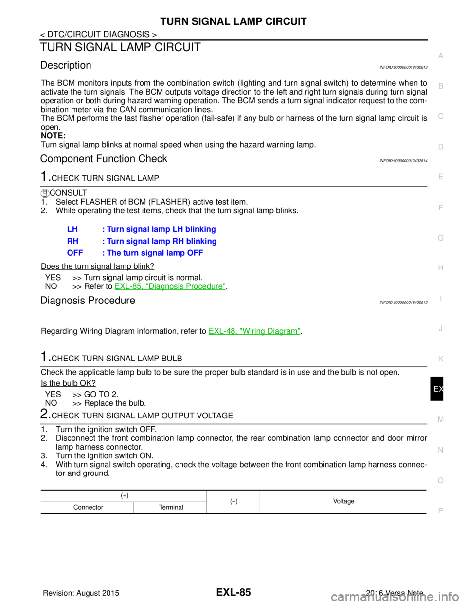
1.CHECK TURN SIGNAL LAMP
CONSULT
1. Select FLASHER of BCM (FLASHER) active test item.
2. While operating the test items, check that the turn signal lamp blinks.
Does the turn signal lamp blink?
YES >> Turn signal lamp circuit is normal.
NO >> Refer to EXL-85, "
Diagnosis Procedure".
Diagnosis ProcedureINFOID:0000000012432815
Regarding Wiring Diagram information, refer to EXL-48, "Wiring Diagram".
1.CHECK TURN SIGNAL LAMP BULB
Check the applicable lamp bulb to be sure the proper bulb standard is in use and the bulb is not open.
Is the bulb OK?
YES >> GO TO 2.
NO >> Replace the bulb.
2.CHECK TURN SIGNAL LA MP OUTPUT VOLTAGE
1. Turn the ignition switch OFF.
2. Disconnect the front combination lamp connector, the rear combination lamp connector and door mirror
lamp harness connector.
3. Turn the ignition switch ON.
4. With turn signal switch operating, check the vo ltage between the front combination lamp harness connec-
tor and ground. LH : Turn signal lamp LH blinking
RH : Turn signal lamp RH blinking
OFF : The turn signal lamp OFF
(+)
(−) Voltage
Connector Terminal
Revision: August 2015 2016 Versa Note
cardiagn.com