2016 NISSAN NOTE warning
[x] Cancel search: warningPage 1819 of 3641
FAX-2
< PRECAUTION >
PRECAUTIONS
PRECAUTION
PRECAUTIONS
Precaution for Supplemental Restraint System (SRS) "AIR BAG" and "SEAT BELT
PRE-TENSIONER"
INFOID:0000000012431882
The Supplemental Restraint System such as “A IR BAG” and “SEAT BELT PRE-TENSIONER”, used along
with a front seat belt, helps to reduce the risk or severity of injury to the driver and front passenger for certain
types of collision. Information necessary to service the system safely is included in the SR and SB section of
this Service Manual.
WARNING:
• To avoid rendering the SRS inopera tive, which could increase the risk of personal injury or death in
the event of a collision which would result in air bag inflation, all maintenance must be performed by
an authorized NISSAN/INFINITI dealer.
• Improper maintenance, including in correct removal and installation of the SRS, can lead to personal
injury caused by unintent ional activation of the system. For re moval of Spiral Cable and Air Bag
Module, see the SR section.
• Do not use electrical test equipmen t on any circuit related to the SRS unless instructed to in this
Service Manual. SRS wiring harn esses can be identified by yellow and/or orange harnesses or har-
ness connectors.
PRECAUTIONS WHEN USING POWER TOOLS (AIR OR ELECTRIC) AND HAMMERS
WARNING:
• When working near the Airbag Diagnosis Sensor Unit or other Airbag System sensors with the Igni-
tion ON or engine running, DO NOT use air or electri c power tools or strike near the sensor(s) with a
hammer. Heavy vibration could activate the sensor( s) and deploy the air bag(s), possibly causing
serious injury.
• When using air or electric power tools or hammers , always switch the Ignition OFF, disconnect the
battery and wait at least three minutes before performing any service.
Precaution for Drive ShaftINFOID:0000000012431883
Observe the following precautions when disassembling and assembling drive shaft.
• Do not disassemble joint sub-assembly because it is non-overhaul parts.
• Perform work in a location which is as dust-free as possible.
• Clean the parts, before disassembling and assembling.
• Prevent the entry of foreign objects dur ing disassembly of the service location.
• Reassemble disassembled parts carefully in the correct order. If work is interrupted, a clean cover must be placed over parts.
• Use paper waste. Fabric shop cloths must not be used because of the danger of lint adhering to parts.
• Clean disassembled parts (except for rubber parts) with kerosene which shall be removed by blowing with air or wiping with paper waste.
Precautions for Wheel Hub and KnuckleINFOID:0000000012431884
Observe the following precautions when assembling wheel hub and knuckle.
• Perform work in a location which is as dust-free as possible.
• Use paper waste. Fabric shop cloths must not be used because of the danger of lint adhering to parts.
• If any of wheel hub, steering knuckle, wheel bearing, and wheel hub lock nut is dropped, it must not be used.
• Always check that the tools used for press-fit work of wheel hub and wheel bearing have no wear and defor- mation so that a pressure can be applied vertically.
Revision: August 2015 2016 Versa Note
cardiagn.com
Page 1847 of 3641
FSU-2
< PRECAUTION >
PRECAUTIONS
PRECAUTION
PRECAUTIONS
Precaution for Supplemental Restraint System (SRS) "AIR BAG" and "SEAT BELT
PRE-TENSIONER"
INFOID:0000000012430294
The Supplemental Restraint System such as “A IR BAG” and “SEAT BELT PRE-TENSIONER”, used along
with a front seat belt, helps to reduce the risk or severity of injury to the driver and front passenger for certain
types of collision. Information necessary to service the system safely is included in the SR and SB section of
this Service Manual.
WARNING:
• To avoid rendering the SRS inopera tive, which could increase the risk of personal injury or death in
the event of a collision which would result in air bag inflation, all maintenance must be performed by
an authorized NISSAN/INFINITI dealer.
• Improper maintenance, including in correct removal and installation of the SRS, can lead to personal
injury caused by unintent ional activation of the system. For re moval of Spiral Cable and Air Bag
Module, see the SR section.
• Do not use electrical test equipmen t on any circuit related to the SRS unless instructed to in this
Service Manual. SRS wiring harn esses can be identified by yellow and/or orange harnesses or har-
ness connectors.
PRECAUTIONS WHEN USING POWER TOOLS (AIR OR ELECTRIC) AND HAMMERS
WARNING:
• When working near the Airbag Diagnosis Sensor Unit or other Airbag System sensors with the Igni-
tion ON or engine running, DO NOT use air or electri c power tools or strike near the sensor(s) with a
hammer. Heavy vibration could activate the sensor( s) and deploy the air bag(s), possibly causing
serious injury.
• When using air or electric power tools or hammers , always switch the Ignition OFF, disconnect the
battery and wait at least three minutes before performing any service.
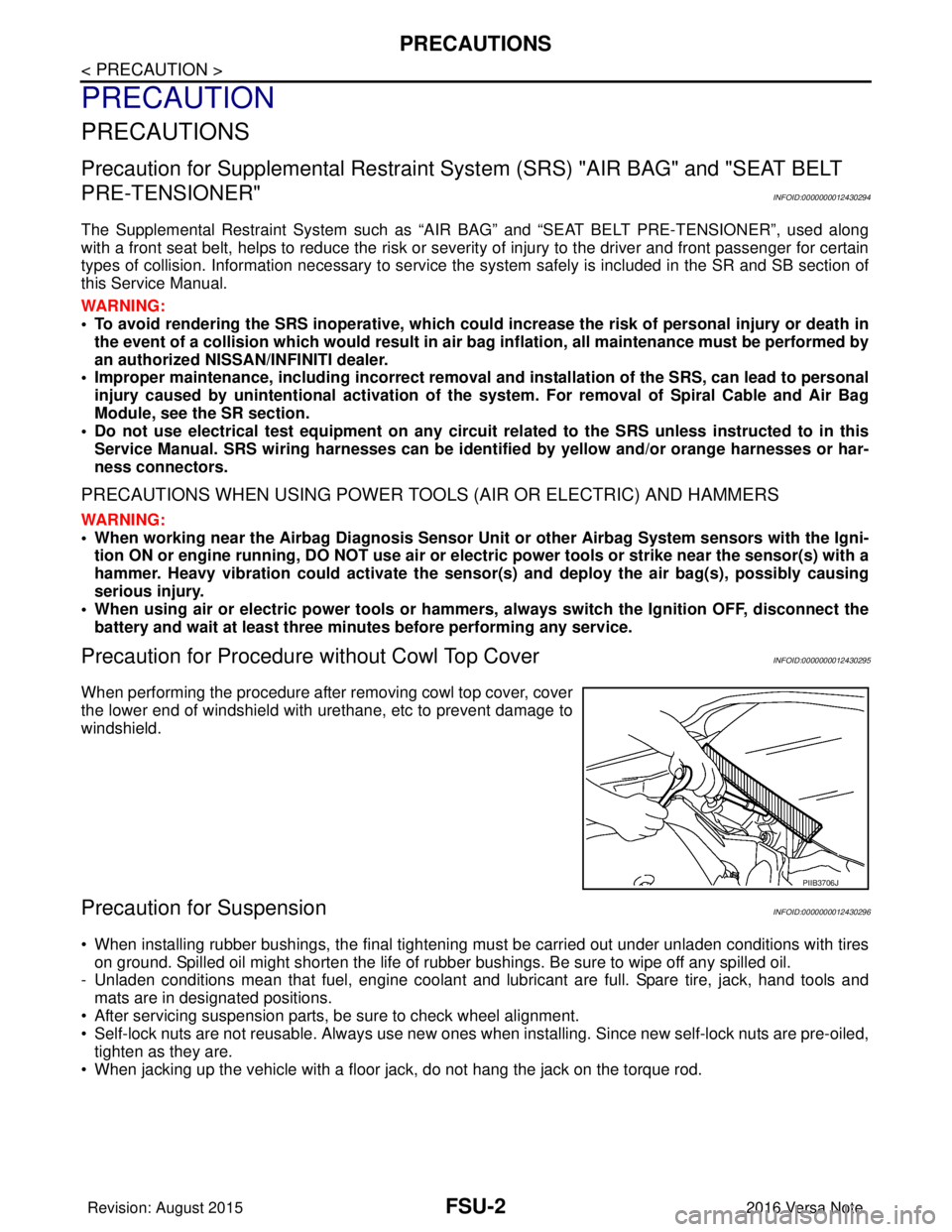
Precaution for Procedure without Cowl Top CoverINFOID:0000000012430295
When performing the procedure after removing cowl top cover, cover
the lower end of windshield with urethane, etc to prevent damage to
windshield.
Precaution for SuspensionINFOID:0000000012430296
• When installing rubber bushings, the final tightening mu st be carried out under unladen conditions with tires
on ground. Spilled oil might shorten the life of rubber bushings. Be sure to wipe off any spilled oil.
- Unladen conditions mean that fuel, engine coolant and lubricant are full. Spare tire, jack, hand tools and mats are in designated positions.
• After servicing suspension parts, be sure to check wheel alignment.
• Self-lock nuts are not reusable. Always use new ones when installing. Since new self-lock nuts are pre-oiled,
tighten as they are.
• When jacking up the vehicle with a floor jack, do not hang the jack on the torque rod.
PIIB3706J
Revision: August 2015 2016 Versa Note
cardiagn.com
Page 1852 of 3641
WHEEL ALIGNMENTFSU-7
< PERIODIC MAINTENANCE >
C
DF
G H
I
J
K L
M A
B
FSU
N
O P
WHEEL ALIGNMENT
InspectionINFOID:0000000012430301
PRELIMINARY INSPECTION
WARNING:
Always adjust the wheel alignment with the vehicle on a flat surface.
NOTE:
If the wheel alignment is out of s pecification, inspect and replace any damaged or worn rear suspension parts
before making any adjustments.
1. Check and adjust the wheel alignment with the vehicle under unladen conditions. “Unladen conditions”
means that the fuel, engine coolant, and lubricants are full; the spare tire, jack, hand tools and mats are in
designated positions.
2. Check the tires for incorrect air pressure and excessive wear.
3. Check the wheels for run out and damage. Refer to WT-54, "
Wheel".
4. Check the wheel bearing axial end play. Refer to FAX-27, "
Wheel Bearing".
5. Check the shock absorbers for leaks or damage.
6. Check each mount point of the suspension co mponents for any excessive looseness or damage.
7. Check each link, arm, and the suspension member for any damage.
8. Check the vehicle height. Refer to FSU-21, "
Wheelarch Height (Unladen*)".
GENERAL INFORMATION AND RECOMMENDATIONS
1. A Four-Wheel Thrust Alignment should be performed.
• This type of alignment is recomm ended for any NISSAN/INFINITI vehicle.
• The four-wheel “thrust” process helps ensure that the vehicle is properly aligned and the steering wheel
is centered.
• The alignment machine itself should be capabl e of accepting any NISSAN/INFINITI vehicle.
• The alignment machine should be checked to ensure that it is level.
2. Make sure the alignment machine is properly calibrated. • Your alignment machine should be regularly calibrated in order to give correct information.
• Check with the manufacturer of your specific a lignment machine for their recommended Service/Cali-
bration Schedule.
ALIGNMENT PROCESS
IMPORTANT: Use only the alignment specifications listed in this Service Manual. Refer to FSU-20, "Wheel
Alignment (Unladen*1)".
• When displaying the alignment settings, many alignment machines use “indicators”: (Green/red, plus or
minus, Go/No Go). Do NOT use these indicators.
- The alignment specifications programmed into your alignment machine that operate these indicators may
not be correct.
- This may result in an ERROR.
• Most camera-type alignment machines are equipped with "Rolling Compensation" method and optional
"Jacking Compensation" method to "compensate" the alignment targets or head units.
"Rolling Compensation" is the preferred method.
- If using the "Rolling Compensation" method, after inst alling the alignment targets or head units, push or pull
on the rear wheel to move the vehicle. Do not push or pull on the vehicle body.
- If using the "Jacking Compensation" method, after inst alling the alignment targets or head units, raise the
vehicle and rotate the wheels 1/2 turn in either direction.
NOTE:
Do not use the "Rolling Compensation" method if you are using sensor-type alignment equipment.
• Follow all instructions for the alignment machine you're using for more information.
CAMBER, CASTER AND KINGPIN INCLINATION ANGLES INSPECTION
• Camber, caster, kingpin inclination angles cannot be adjusted.
• Before inspection, set the front wheels onto a turning radius gauge. Set the rear wheels onto a pad that has
the same height so the vehicle will remain horizontal.
TOTAL TOE-IN INSPECTION
Measure the total toe-in using the following procedure.
Revision: August 2015 2016 Versa Note
cardiagn.com
Page 1853 of 3641
FSU-8
< PERIODIC MAINTENANCE >
WHEEL ALIGNMENT
WARNING:
• Always perform the following procedure on a flat surface.
• Make sure that no person is in fr ont of vehicle before pushing it.
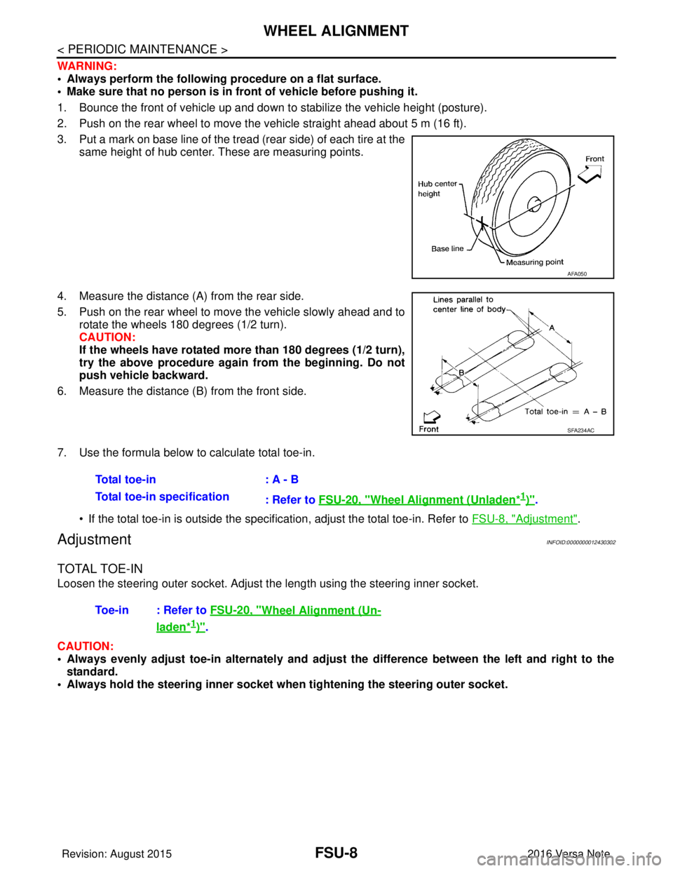
1. Bounce the front of vehicle up and down to stabilize the vehicle height (posture).
2. Push on the rear wheel to move the vehicle straight ahead about 5 m (16 ft).
3. Put a mark on base line of the tread (rear side) of each tire at the same height of hub center. These are measuring points.
4. Measure the distance (A) from the rear side.
5. Push on the rear wheel to move the vehicle slowly ahead and to rotate the wheels 180 degrees (1/2 turn).
CAUTION:
If the wheels have rotated more than 180 degrees (1/2 turn),
try the above procedure again from the beginning. Do not
push vehicle backward.
6. Measure the distance (B) from the front side.
7. Use the formula below to calculate total toe-in.
• If the total toe-in is outside the specification, adjust the total toe-in. Refer to FSU-8, "
Adjustment".
AdjustmentINFOID:0000000012430302
TOTAL TOE-IN
Loosen the steering outer socket. Adjust the length using the steering inner socket.
CAUTION:
• Always evenly adjust toe-in alternately and adjust the difference be tween the left and right to the
standard.
• Always hold the steering inner socket wh en tightening the steering outer socket.
AFA050
SFA234AC
Total toe-in: A - B
Total toe-in specification : Refer to FSU-20, "
Wheel Alignment (Unladen*1)".
Toe-in : Refer to FSU-20, "
Wheel Alignment (Un-
laden*1)".
Revision: August 2015 2016 Versa Note
cardiagn.com
Page 1861 of 3641
FSU-16
< UNIT DISASSEMBLY AND ASSEMBLY >
FRONT COIL SPRING AND STRUT
UNIT DISASSEMBLY AND ASSEMBLY
FRONT COIL SPRING AND STRUT
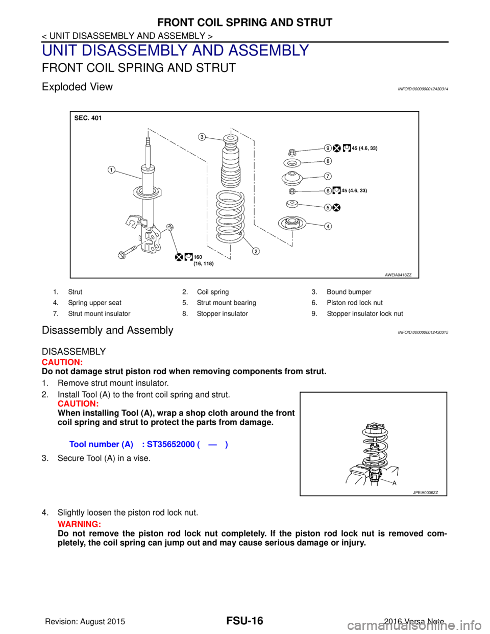
Exploded ViewINFOID:0000000012430314
Disassembly and AssemblyINFOID:0000000012430315
DISASSEMBLY
CAUTION:
Do not damage strut piston rod when removing components from strut.
1. Remove strut mount insulator.
2. Install Tool (A) to the front coil spring and strut. CAUTION:
When installing Tool (A), wrap a shop cloth around the front
coil spring and strut to protect the parts from damage.
3. Secure Tool (A) in a vise.
4. Slightly loosen the piston rod lock nut. WARNING:
Do not remove the piston rod lock nut completely. If the piston rod lock nut is removed com-
pletely, the coil spring can jump out and may cause serious damage or injury.
1. Strut 2. Coil spring3. Bound bumper
4. Spring upper seat 5. Strut mount bearing 6. Piston rod lock nut
7. Strut mount insulator 8. Stopper insulator 9. Stopper insulator lock nut
AWEIA0418ZZ
Tool number (A) : ST35652000 ( — )
JPEIA0006ZZ
Revision: August 2015 2016 Versa Note
cardiagn.com
Page 1862 of 3641
FRONT COIL SPRING AND STRUTFSU-17
< UNIT DISASSEMBLY AND ASSEMBLY >
C
DF
G H
I
J
K L
M A
B
FSU
N
O P
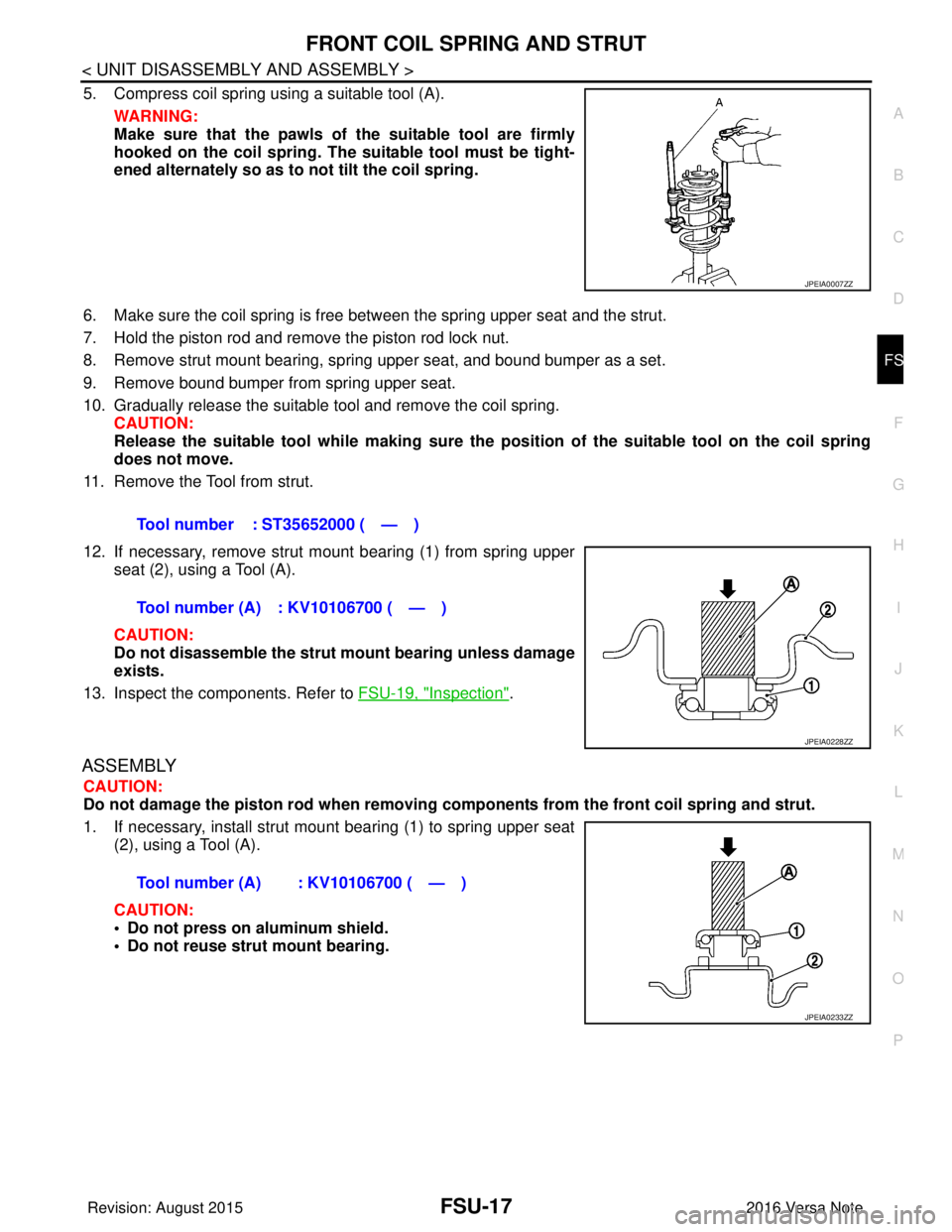
5. Compress coil spring using a suitable tool (A). WARNING:
Make sure that the pawls of the suitable tool are firmly
hooked on the coil spring. The suitable tool must be tight-
ened alternately so as to not tilt the coil spring.
6. Make sure the coil spring is free between the spring upper seat and the strut.
7. Hold the piston rod and remove the piston rod lock nut.
8. Remove strut mount bearing, spri ng upper seat, and bound bumper as a set.
9. Remove bound bumper from spring upper seat.
10. Gradually release the suitable tool and remove the coil spring. CAUTION:
Release the suitable tool while making sure the pos ition of the suitable tool on the coil spring
does not move.
11. Remove the Tool from strut.
12. If necessary, remove strut mount bearing (1) from spring upper seat (2), using a Tool (A).
CAUTION:
Do not disassemble the strut mount bearing unless damage
exists.
13. Inspect the components. Refer to FSU-19, "
Inspection".
ASSEMBLY
CAUTION:
Do not damage the piston rod when removing components from th e front coil spring and strut.
1. If necessary, install strut mount bearing (1) to spring upper seat (2), using a Tool (A).
CAUTION:
• Do not press on aluminum shield.
• Do not reuse strut mount bearing.
JPEIA0007ZZ
Tool number : ST35652000 ( — )
Tool number (A) : KV10106700 ( — )
JPEIA0228ZZ
Tool number (A) : KV10106700 ( — )
JPEIA0233ZZ
Revision: August 2015 2016 Versa Note
cardiagn.com
Page 1863 of 3641
FSU-18
< UNIT DISASSEMBLY AND ASSEMBLY >
FRONT COIL SPRING AND STRUT
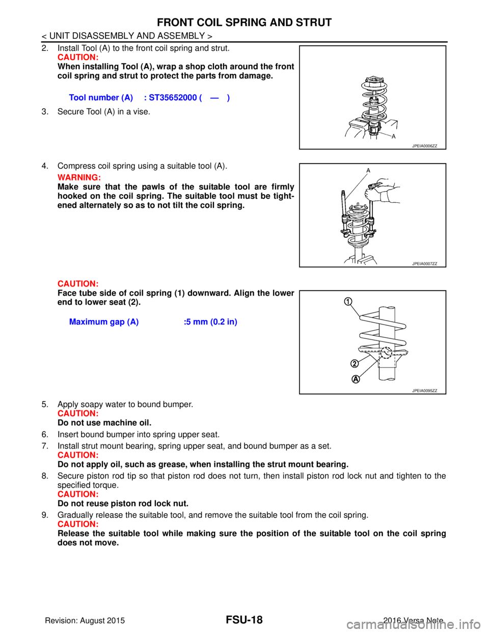
2. Install Tool (A) to the front coil spring and strut.CAUTION:
When installing Tool (A), wrap a shop cloth around the front
coil spring and strut to protect the parts from damage.
3. Secure Tool (A) in a vise.
4. Compress coil spring using a suitable tool (A). WARNING:
Make sure that the pawls of the suitable tool are firmly
hooked on the coil spring. The suitable tool must be tight-
ened alternately so as to not tilt the coil spring.
CAUTION:
Face tube side of coil spring (1) downward. Align the lower
end to lower seat (2).
5. Apply soapy water to bound bumper. CAUTION:
Do not use machine oil.
6. Insert bound bumper into spring upper seat.
7. Install strut mount bearing, spring upper seat, and bound bumper as a set. CAUTION:
Do not apply oil, such as grease, when installing the strut mount bearing.
8. Secure piston rod tip so that piston rod does not turn, then install piston rod lock nut and tighten to the specified torque.
CAUTION:
Do not reuse piston rod lock nut.
9. Gradually release the suitable tool, and remove the suitable tool from the coil spring. CAUTION:
Release the suitable tool while making sure the po sition of the suitable tool on the coil spring
does not move. Tool number (A) : ST35652000 ( — )
JPEIA0006ZZ
JPEIA0007ZZ
Maximum gap (A)
:5 mm (0.2 in)
JPEIA0095ZZ
Revision: August 2015 2016 Versa Note
cardiagn.com
Page 1868 of 3641
FL-2
< PRECAUTION >
PRECAUTIONS
PRECAUTION
PRECAUTIONS
Precaution for Supplemental Restraint System (SRS) "AIR BAG" and "SEAT BELT
PRE-TENSIONER"
INFOID:0000000012432103
The Supplemental Restraint System such as “A IR BAG” and “SEAT BELT PRE-TENSIONER”, used along
with a front seat belt, helps to reduce the risk or severity of injury to the driver and front passenger for certain
types of collision. Information necessary to service the system safely is included in the SR and SB section of
this Service Manual.
WARNING:
• To avoid rendering the SRS inopera tive, which could increase the risk of personal injury or death in
the event of a collision which would result in air bag inflation, all maintenance must be performed by
an authorized NISSAN/INFINITI dealer.
• Improper maintenance, including in correct removal and installation of the SRS, can lead to personal
injury caused by unintent ional activation of the system. For re moval of Spiral Cable and Air Bag
Module, see the SR section.
• Do not use electrical test equipmen t on any circuit related to the SRS unless instructed to in this
Service Manual. SRS wiring harn esses can be identified by yellow and/or orange harnesses or har-
ness connectors.
PRECAUTIONS WHEN USING POWER TOOLS (AIR OR ELECTRIC) AND HAMMERS
WARNING:
• When working near the Airbag Diagnosis Sensor Unit or other Airbag System sensors with the Igni-
tion ON or engine running, DO NOT use air or electri c power tools or strike near the sensor(s) with a
hammer. Heavy vibration could activate the sensor( s) and deploy the air bag(s), possibly causing
serious injury.
• When using air or electric power tools or hammers , always switch the Ignition OFF, disconnect the
battery and wait at least three minutes before performing any service.
General PrecautionINFOID:0000000012432104
WARNING:
When replacing fuel line parts, be sure to observe the following.
• Put a “CAUTION: FLAMMABLE” sign in the work area.
• Be sure to work in a well ventilated area and have a CO
2 fire extinguisher.
• Do not smoke while working on the fuel system. Keep open flames and sparks away from the work
area.
CAUTION:
• Before removing fuel line parts, carry out the following procedures:
- Put drained fuel in an explosi on-proof container and put the lid on securely. Keep the container in
safe area.
- Release fuel pressure from the fuel lines. Refer to EC-1
37, "Work Procedure" .
- Disconnect the battery ground
cable.
• Always replace O-rings and clamps with new ones.
• Do not kink or twist tubes when they are being installed.
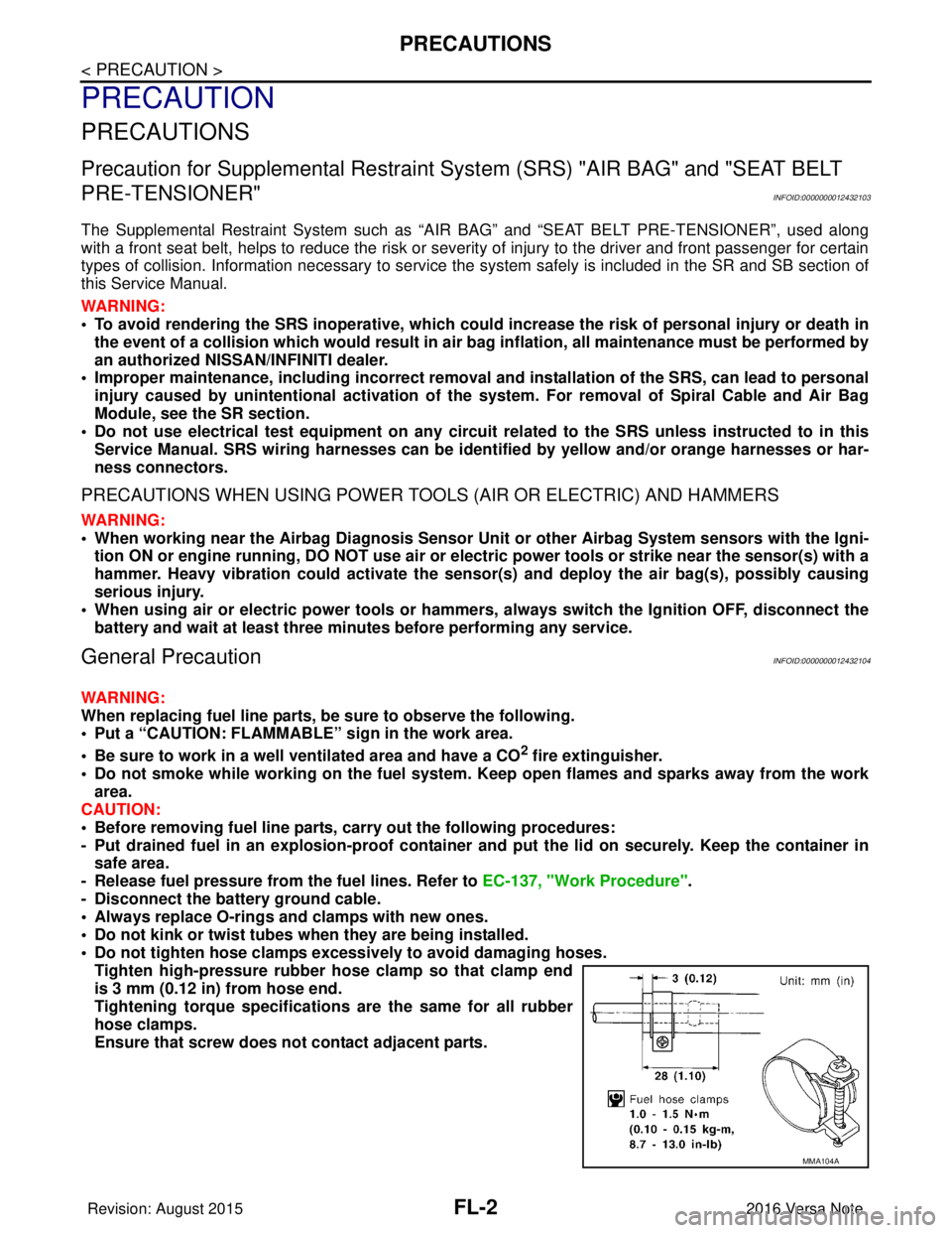
• Do not tighten hose clamps excessi vely to avoid damaging hoses.
Tighten high-pressure rubber hose clamp so that clamp end
is 3 mm (0.12 in) from hose end.
Tightening torque specificati ons are the same for all rubber
hose clamps.
Ensure that screw does not contact adjacent parts.
MMA104A
Revision: August 2015 2016 Versa Note
cardiagn.com