2016 NISSAN NOTE warning
[x] Cancel search: warningPage 1744 of 3641

EXL-92
< SYMPTOM DIAGNOSIS >
EXTERIOR LIGHTING SYSTEM SYMPTOMS
Front fog lamp is not
turned ON.One side
• Front fog lamp bulb
• Harness between the front fog
lamp and ground Front fog lamp circuit
Refer to
EXL-88
.
Both sides —Symptom diagnosis
"BOTH SIDE FRONT FOG LAMPS
ARE NOT TURNED ON"
Refer to
EXL-96
.
Parking lamp is not
turned ON. One side
•Fuse
• Parking lamp bulb
• Harness between IPDM E/R
and the front/rear combination
lamp
• Front/rear combination lamp
• IPDM E/R Parking lamp circuit
Refer to
EXL-82
.
Both sides —Symptom diagnosis
"PARKING, LICENSE PLATE AND
TAIL LAMPS ARE NOT TURNED
ON"
Refer to
EXL-95
.
Turn signal lamp does
not blink. Indicator lamp is nor-
mal.
(The applicable side
performs the high
flasher activation).• Harness between BCM and
each turn signal lamp
• Turn signal lamp bulb Turn signal lamp circuit
Refer to
EXL-85
.
Turn signal indicator
lamp does not blink. One side
Combination meter —
Both sides
(Always) • Turn signal indicator lamp sig-
nal
• Combination meter
•BCM • Combination meter.
Data monitor "TURN IND"
• BCM (FLASHER) Active test "FLASHER"
Both sides
(Does blink when acti-
vating the hazard
warning lamp with the
ignition switch OFF) • The combination meter power
supply and the ground circuit
• Combination meter Combination meter
Power supply and the ground circuit
Refer to
MWI-43
(Type A).
Refer to MWI-98
(Type B).
Symptom
Possible causeInspection item
Revision: August 2015 2016 Versa Note
cardiagn.com
Page 1754 of 3641
EXL-102
< REMOVAL AND INSTALLATION >
FRONT COMBINATION LAMP
REMOVAL AND INSTALLATION
FRONT COMBINATION LAMP
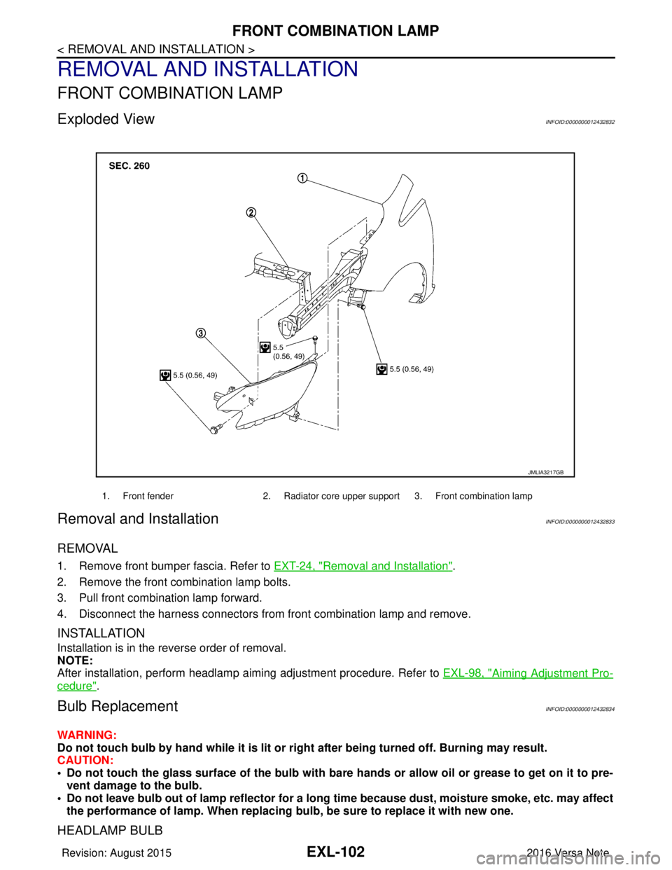
Exploded ViewINFOID:0000000012432832
Removal and InstallationINFOID:0000000012432833
REMOVAL
1. Remove front bumper fascia. Refer to EXT-24, "Removal and Installation".
2. Remove the front combination lamp bolts.
3. Pull front combination lamp forward.
4. Disconnect the harness connectors from front combination lamp and remove.
INSTALLATION
Installation is in the reverse order of removal.
NOTE:
After installation, perform headlamp aiming adjustment procedure. Refer to EXL-98, "
Aiming Adjustment Pro-
cedure".
Bulb ReplacementINFOID:0000000012432834
WARNING:
Do not touch bulb by hand while it is lit or right after being turned off. Burning may result.
CAUTION:
• Do not touch the glass surface of the bulb with bare hands or allow oil or grease to get on it to pre-
vent damage to the bulb.
• Do not leave bulb out of lamp reflector for a long time because dust, moisture smoke, etc. may affect
the performance of lamp. When replacing bulb, be sure to replace it with new one.
HEADLAMP BULB
1. Front fender2. Radiator core upper support 3. Front combination lamp
JMLIA3217GB
Revision: August 2015 2016 Versa Note
cardiagn.com
Page 1757 of 3641
FRONT FOG LAMPEXL-105
< REMOVAL AND INSTALLATION >
C
DE
F
G H
I
J
K
M A
B
EXL
N
O P
Bulb ReplacementINFOID:0000000012432837
WARNING:
Do not touch bulb by hand while it is lit or right after being turned off. Burning may result.
CAUTION:
• Do not touch the glass surface of the bulb with bare hands or allow oi l or grease to get on it to pre-
vent damage to the bulb.
• Do not leave bulb out of lamp reflector for a long time because dust, moisture smoke, etc. may affect
the performance of lamp. When replacing bulb, be sure to replace it with new one.
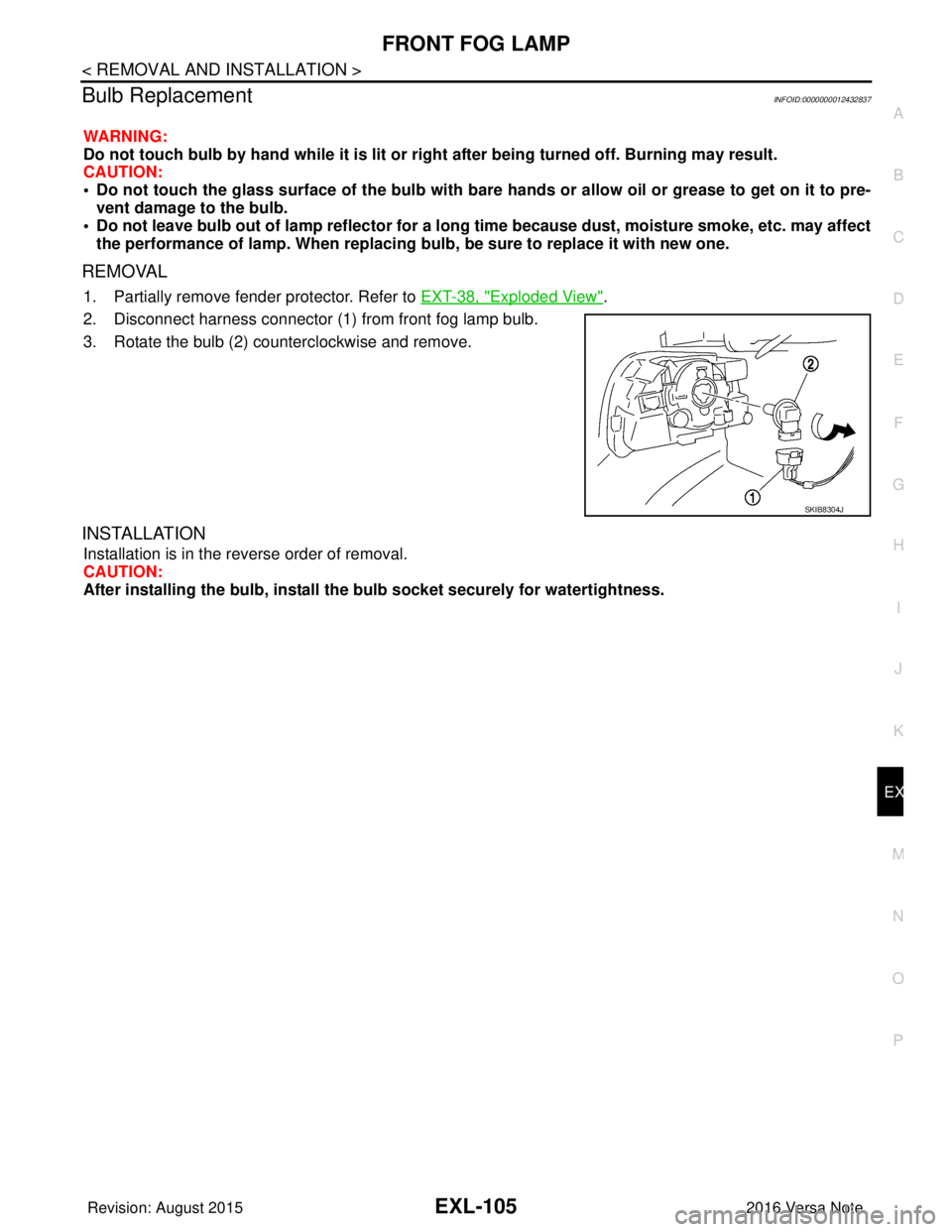
REMOVAL
1. Partially remove fender protector. Refer to EXT-38, "Exploded View".
2. Disconnect harness connector (1) from front fog lamp bulb.
3. Rotate the bulb (2) counterclockwise and remove.
INSTALLATION
Installation is in the reverse order of removal.
CAUTION:
After installing the bulb, install the bulb socket securely for watertightness.
SKIB8304J
Revision: August 2015 2016 Versa Note
cardiagn.com
Page 1761 of 3641
REAR COMBINATION LAMPEXL-109
< REMOVAL AND INSTALLATION >
C
DE
F
G H
I
J
K
M A
B
EXL
N
O P
REAR COMBINATION LAMP
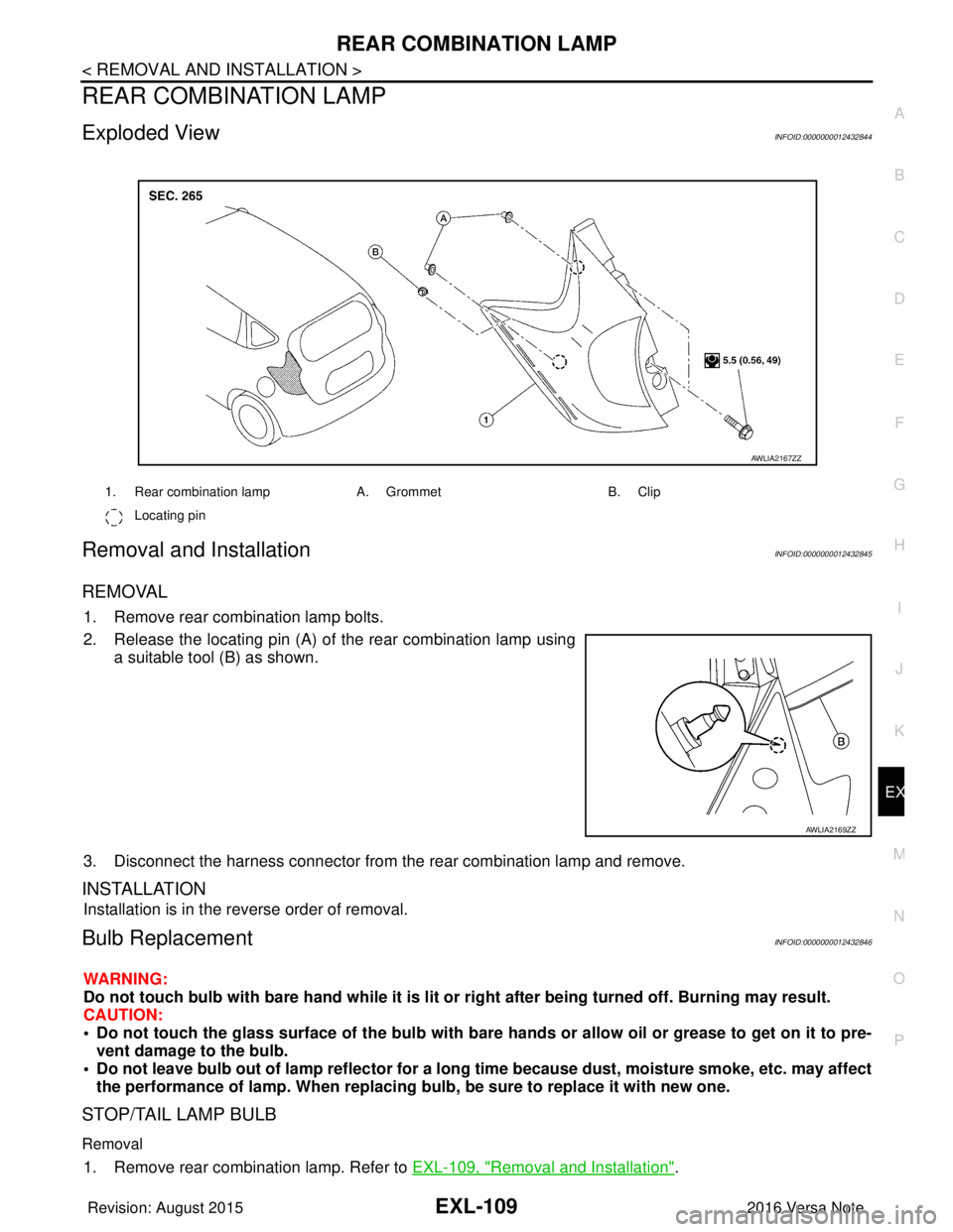
Exploded ViewINFOID:0000000012432844
Removal and InstallationINFOID:0000000012432845
REMOVAL
1. Remove rear combination lamp bolts.
2. Release the locating pin (A) of the rear combination lamp using a suitable tool (B) as shown.
3. Disconnect the harness connector from the rear combination lamp and remove.
INSTALLATION
Installation is in the reverse order of removal.
Bulb ReplacementINFOID:0000000012432846
WARNING:
Do not touch bulb with bare hand while it is lit or right after being turned off. Burning may result.
CAUTION:
• Do not touch the glass surface of the bulb with bare hands or allow oi l or grease to get on it to pre-
vent damage to the bulb.
• Do not leave bulb out of lamp reflector for a long time because dust, moisture smoke, etc. may affect the performance of lamp. When replacing bulb, be sure to replace it with new one.
STOP/TAIL LAMP BULB
Removal
1. Remove rear combination lamp. Refer to EXL-109, "Removal and Installation".
1. Rear combination lampA. GrommetB. Clip
Locating pin
AWLIA2167ZZ
AWLIA2169ZZ
Revision: August 2015 2016 Versa Note
cardiagn.com
Page 1764 of 3641
EXL-112
< REMOVAL AND INSTALLATION >
LICENSE PLATE LAMP
LICENSE PLATE LAMP
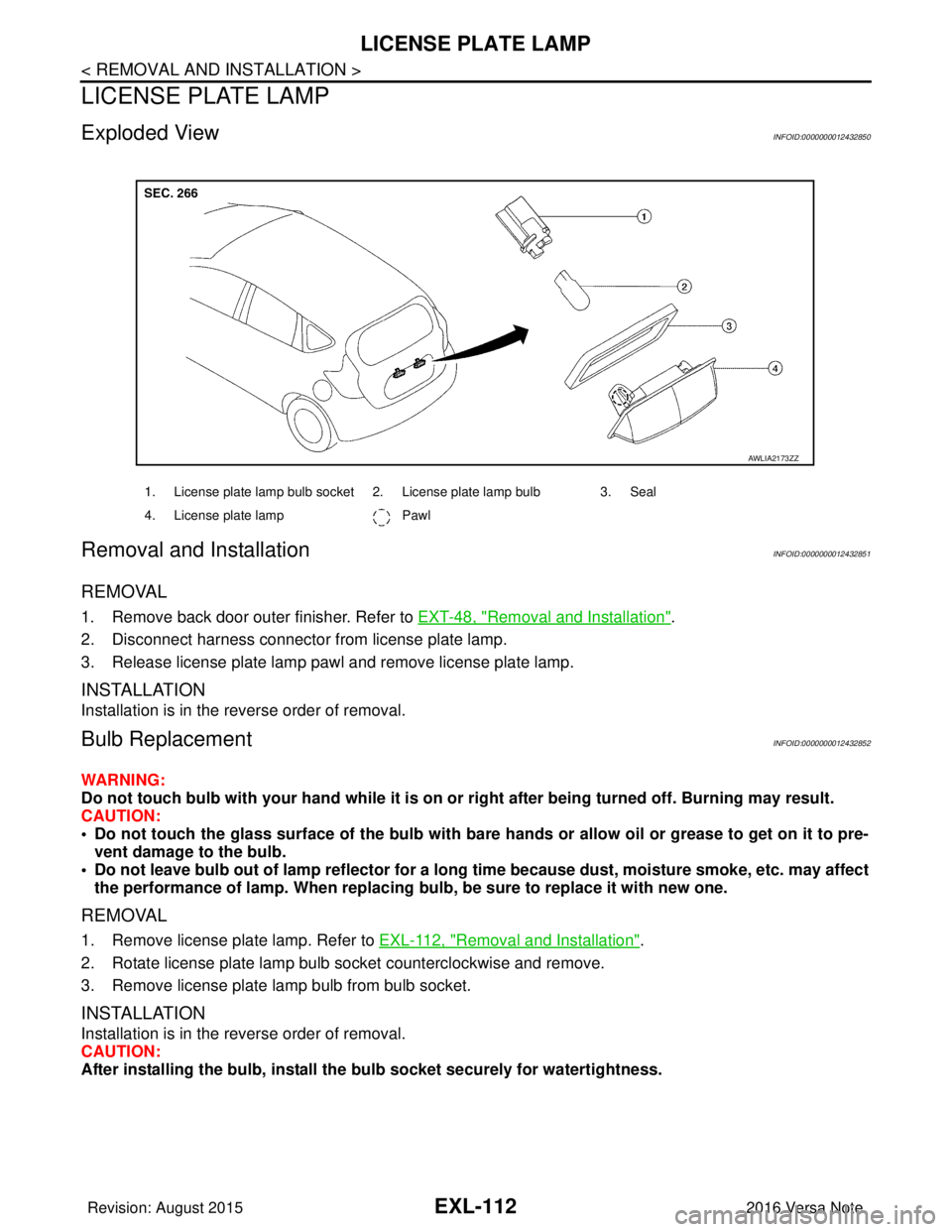
Exploded ViewINFOID:0000000012432850
Removal and InstallationINFOID:0000000012432851
REMOVAL
1. Remove back door outer finisher. Refer to EXT-48, "Removal and Installation".
2. Disconnect harness connector from license plate lamp.
3. Release license plate lamp pawl and remove license plate lamp.
INSTALLATION
Installation is in the reverse order of removal.
Bulb ReplacementINFOID:0000000012432852
WARNING:
Do not touch bulb with your hand while it is on or right after being turned off. Burning may result.
CAUTION:
• Do not touch the glass surface of the bulb with bare hands or allow oil or grease to get on it to pre- vent damage to the bulb.
• Do not leave bulb out of lamp reflector for a long time because dust, moisture smoke, etc. may affect
the performance of lamp. When replacing bulb, be sure to replace it with new one.
REMOVAL
1. Remove license plate lamp. Refer to EXL-112, "Removal and Installation".
2. Rotate license plate lamp bulb socket counterclockwise and remove.
3. Remove license plate lamp bulb from bulb socket.
INSTALLATION
Installation is in the reverse order of removal.
CAUTION:
After installing the bulb, install the bulb socket securely for watertightness.
1. License plate lamp bulb socket 2. License plate lamp bulb 3. Seal
4. License plate lamp Pawl
AWLIA2173ZZ
Revision: August 2015 2016 Versa Note
cardiagn.com
Page 1765 of 3641
FRONT COMBINATION LAMPEXL-113
< UNIT DISASSEMBLY AND ASSEMBLY >
C
DE
F
G H
I
J
K
M A
B
EXL
N
O P
UNIT DISASSEMBLY AND ASSEMBLY
FRONT COMBINATION LAMP
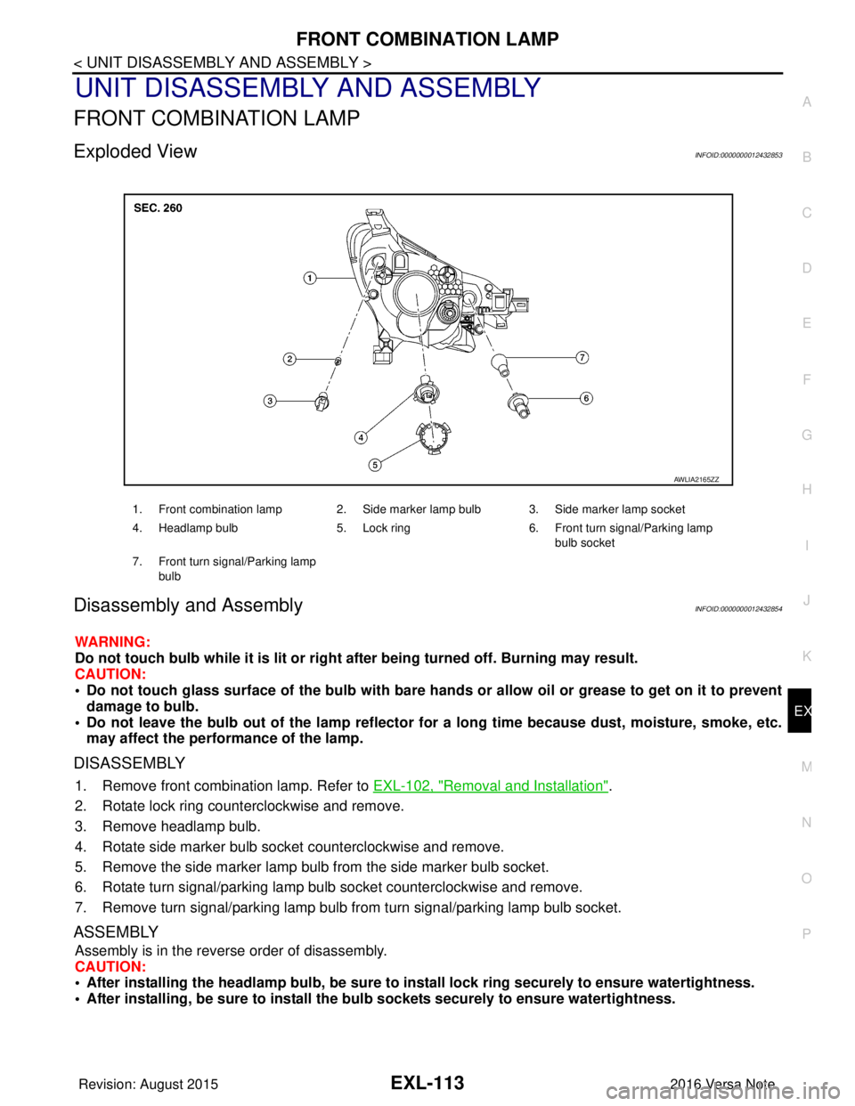
Exploded ViewINFOID:0000000012432853
Disassembly and AssemblyINFOID:0000000012432854
WARNING:
Do not touch bulb while it is lit or right after being turned off. Burning may result.
CAUTION:
• Do not touch glass surface of the bulb with bare hands or allow oil or grease to get on it to prevent damage to bulb.
• Do not leave the bulb out of the lamp reflector for a long time because dust , moisture, smoke, etc.
may affect the performance of the lamp.
DISASSEMBLY
1. Remove front combination lamp. Refer to EXL-102, "Removal and Installation".
2. Rotate lock ring counterclockwise and remove.
3. Remove headlamp bulb.
4. Rotate side marker bulb socket counterclockwise and remove.
5. Remove the side marker lamp bulb from the side marker bulb socket.
6. Rotate turn signal/parking lamp bulb socket counterclockwise and remove.
7. Remove turn signal/parking lamp bulb from turn signal/parking lamp bulb socket.
ASSEMBLY
Assembly is in the reverse order of disassembly.
CAUTION:
• After installing the headlamp bulb, be sure to install lock ring securely to ensure watertightness.
• After installing, be sure to install the bulb sockets securely to ensure watertightness.
1. Front combination lamp 2. Side marker lamp bulb 3. Side marker lamp socket
4. Headlamp bulb 5. Lock ring 6. Front turn signal/Parking lamp
bulb socket
7. Front turn signal/Parking lamp bulb
AWLIA2165ZZ
Revision: August 2015 2016 Versa Note
cardiagn.com
Page 1766 of 3641
EXL-114
< UNIT DISASSEMBLY AND ASSEMBLY >
REAR COMBINATION LAMP
REAR COMBINATION LAMP
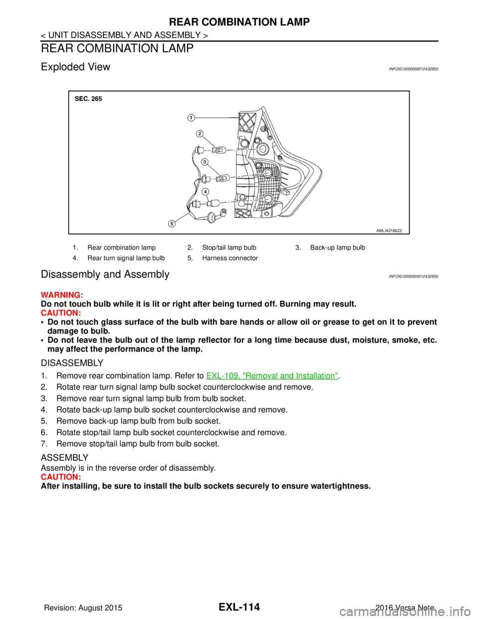
Exploded ViewINFOID:0000000012432855
Disassembly and Assembly INFOID:0000000012432856
WARNING:
Do not touch bulb while it is lit or right after being turned off. Burning may result.
CAUTION:
• Do not touch glass surface of the bulb with bare hands or allow oil or grease to get on it to preventdamage to bulb.
• Do not leave the bulb out of the lamp reflector fo r a long time because dust, moisture, smoke, etc.
may affect the performance of the lamp.
DISASSEMBLY
1. Remove rear combination lamp. Refer to EXL-109, "Removal and Installation".
2. Rotate rear turn signal lamp bulb socket counterclockwise and remove.
3. Remove rear turn signal lamp bulb from bulb socket.
4. Rotate back-up lamp bulb socket counterclockwise and remove.
5. Remove back-up lamp bulb from bulb socket.
6. Rotate stop/tail lamp bulb socket counterclockwise and remove.
7. Remove stop/tail lamp bulb from bulb socket.
ASSEMBLY
Assembly is in the reverse order of disassembly.
CAUTION:
After installing, be sure to install the bu lb sockets securely to ensure watertightness.
1. Rear combination lamp 2. Stop/tail lamp bulb 3. Back-up lamp bulb
4. Rear turn signal lamp bulb 5. Harness connector
AWLIA2166ZZ
Revision: August 2015 2016 Versa Note
cardiagn.com
Page 1770 of 3641
PRECAUTIONSEXT-3
< PRECAUTION >
C
DE
F
G H
I
J
L
M A
B
EXT
N
O P
PRECAUTION
PRECAUTIONS
Precaution for Supplemental Restraint System (SRS) "AIR BAG" and "SEAT BELT
PRE-TENSIONER"
INFOID:0000000012432151
The Supplemental Restraint System such as “AIR BAG” and “SEAT BELT PRE-TENSIONER”, used along
with a front seat belt, helps to reduce the risk or severi ty of injury to the driver and front passenger for certain
types of collision. Information necessary to service the system safely is included in the SR and SB section of
this Service Manual.
WARNING:
• To avoid rendering the SRS inoper ative, which could increase the risk of personal injury or death in
the event of a collision which would result in air bag inflation, all maintenance must be performed by
an authorized NISSAN/INFINITI dealer.
• Improper maintenance, including in correct removal and installation of the SRS, can lead to personal
injury caused by unintentional act ivation of the system. For removal of Spiral Cable and Air Bag
Module, see the SR section.
• Do not use electrical test equipm ent on any circuit related to the SRS unless instructed to in this
Service Manual. SRS wiring harnesses can be identi fied by yellow and/or orange harnesses or har-
ness connectors.
PRECAUTIONS WHEN USING POWER TOOLS (AIR OR ELECTRIC) AND HAMMERS
WARNING:
• When working near the Airbag Diagnosis Sensor Un it or other Airbag System sensors with the Igni-
tion ON or engine running, DO NOT use air or el ectric power tools or strike near the sensor(s) with a
hammer. Heavy vibration could activate the sensor( s) and deploy the air bag(s), possibly causing
serious injury.
• When using air or electric power tools or hammers, always switch the Ignition OFF, disconnect the
battery and wait at least three mi nutes before performing any service.
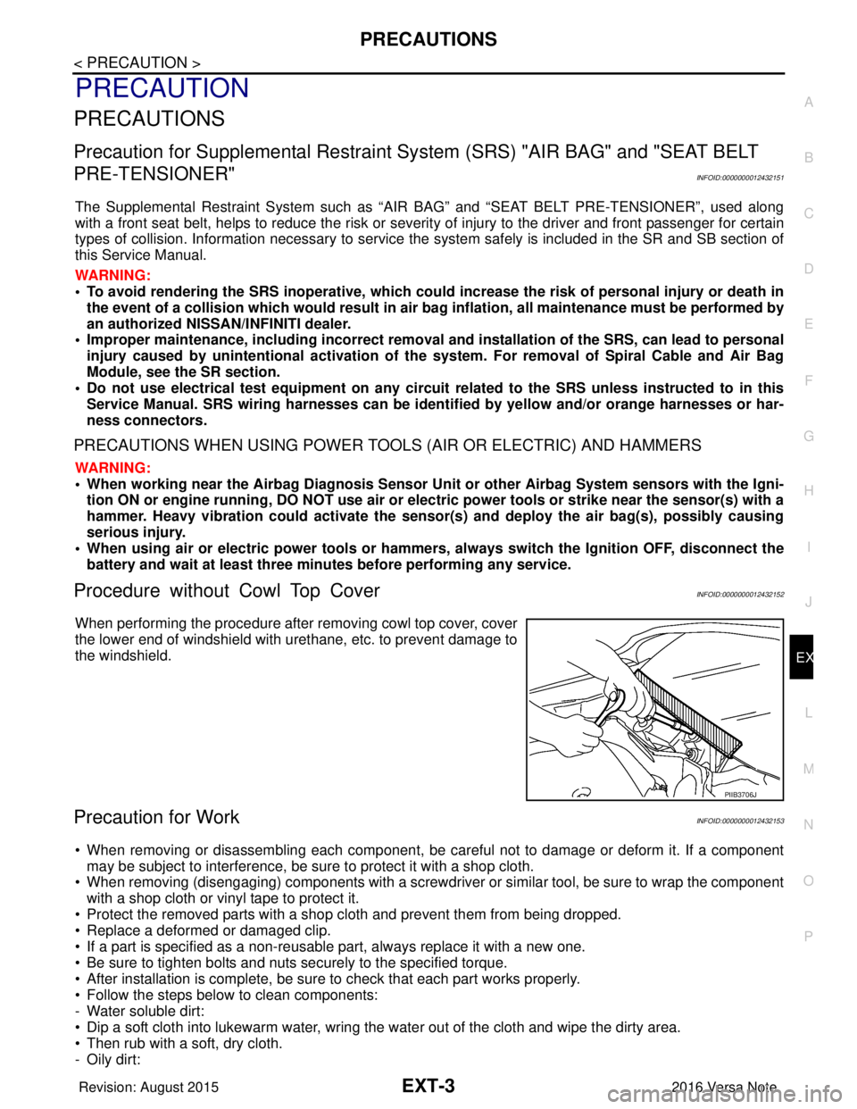
Procedure without Cowl Top CoverINFOID:0000000012432152
When performing the procedure after removing cowl top cover, cover
the lower end of windshield with urethane, etc. to prevent damage to
the windshield.
Precaution for WorkINFOID:0000000012432153
• When removing or disassembling each component, be ca reful not to damage or deform it. If a component
may be subject to interference, be sure to protect it with a shop cloth.
• When removing (disengaging) components with a screwdriver or similar tool, be sure to wrap the component with a shop cloth or vinyl tape to protect it.
• Protect the removed parts with a shop cloth and prevent them from being dropped.
• Replace a deformed or damaged clip.
• If a part is specified as a non-reusabl e part, always replace it with a new one.
• Be sure to tighten bolts and nuts securely to the specified torque.
• After installation is complete, be sure to check that each part works properly.
• Follow the steps below to clean components:
- Water soluble dirt:
• Dip a soft cloth into lukewarm water, wring the water out of the cloth and wipe the dirty area.
• Then rub with a soft, dry cloth.
-Oily dirt:
PIIB3706J
Revision: August 2015 2016 Versa Note
cardiagn.com