2016 NISSAN NOTE sensor
[x] Cancel search: sensorPage 1068 of 3641
![NISSAN NOTE 2016 Service Repair Manual CAMSHAFTEM-67
< REMOVAL AND INSTALLATION > [HR16DE]
C
D
E
F
G H
I
J
K L
M A
EM
NP
O
12. Pull out the stopper pin (A), and then apply the tension to the
timing chain by rotating the crankshaft pulley c NISSAN NOTE 2016 Service Repair Manual CAMSHAFTEM-67
< REMOVAL AND INSTALLATION > [HR16DE]
C
D
E
F
G H
I
J
K L
M A
EM
NP
O
12. Pull out the stopper pin (A), and then apply the tension to the
timing chain by rotating the crankshaft pulley c](/manual-img/5/57363/w960_57363-1067.png)
CAMSHAFTEM-67
< REMOVAL AND INSTALLATION > [HR16DE]
C
D
E
F
G H
I
J
K L
M A
EM
NP
O
12. Pull out the stopper pin (A), and then apply the tension to the
timing chain by rotating the crankshaft pulley clockwise slightly.
13. Pull out the stopper pin of chain tensioner.
14. Install front cover.
15. Return the camshaft sprocket (INT) in the most retarded position:
a. Remove the stopper pin (A) from the camshaft sprocket (INT).
b. Turn the crankshaft pulley (1) slowly clockwise (A) and return the camshaft sprocket (INT) to the most retarded angle position.
• When first turning the crankshaft, the camshaft sprocket (INT)
will turn. Once it is turned more, and the vane (camshaft) also
turns, then it has reached t he most retarded angle position.
• The most retarded angle position can be checked by seeing if the stopper pin groove (A) is shifted clockwise.
• After spinning the crankshaft slightly in the counterclockwise direction, you can check the lock pin has joined by seeing if
the vane (camshaft) and the sprocket move together.
16. Install the camshaft position sensor (PHASE) to the rear end of cylinder head. • Tighten bolts with it completely inserted.
17. Check and adjust valve clearance. Refer to EM-10, "
Inspection and Adjustment".
18. Installation of the remaining components is in the reverse order of removal.
INSPECTION AFTER INSTALLATION
(1) : Plunger
(2) : Chain tensioner
(B) : Lever
(C) : Lever hole
(D) : Front cover has been removed for clarity.
PBIC3772E
(B) : Tape
PBIC3685E
PBIC3704E
(B) : Stopper pin hole
(C) : Most advanced angle
(D) : Lock pin engaged
PBIC3705E
Revision: August 2015 2016 Versa Note
cardiagn.com
Page 1094 of 3641
![NISSAN NOTE 2016 Service Repair Manual CYLINDER BLOCKEM-93
< UNIT DISASSEMBLY AND ASSEMBLY > [HR16DE]
C
D
E
F
G H
I
J
K L
M A
EM
NP
O
CYLINDER BLOCK
Exploded ViewINFOID:0000000012431736
1. Crankshaft position sensor cover 2. Crankshaft pos NISSAN NOTE 2016 Service Repair Manual CYLINDER BLOCKEM-93
< UNIT DISASSEMBLY AND ASSEMBLY > [HR16DE]
C
D
E
F
G H
I
J
K L
M A
EM
NP
O
CYLINDER BLOCK
Exploded ViewINFOID:0000000012431736
1. Crankshaft position sensor cover 2. Crankshaft pos](/manual-img/5/57363/w960_57363-1093.png)
CYLINDER BLOCKEM-93
< UNIT DISASSEMBLY AND ASSEMBLY > [HR16DE]
C
D
E
F
G H
I
J
K L
M A
EM
NP
O
CYLINDER BLOCK
Exploded ViewINFOID:0000000012431736
1. Crankshaft position sensor cover 2. Crankshaft position sensor (POS) 3. O-ring
4. Drain plug 5. Cylinder block 6. Oil level gauge
7. Oil level gauge guide 8. O-ring 9. Knock sensor
AWBIA1621ZZ
Revision: August 2015
2016 Versa Note
cardiagn.com
Page 1095 of 3641
![NISSAN NOTE 2016 Service Repair Manual EM-94
< UNIT DISASSEMBLY AND ASSEMBLY >[HR16DE]
CYLINDER BLOCK
Disassembly and Assembly
INFOID:0000000012431737
DISASSEMBLY
NOTE:
The following procedures explain how to disassem ble the engine with t NISSAN NOTE 2016 Service Repair Manual EM-94
< UNIT DISASSEMBLY AND ASSEMBLY >[HR16DE]
CYLINDER BLOCK
Disassembly and Assembly
INFOID:0000000012431737
DISASSEMBLY
NOTE:
The following procedures explain how to disassem ble the engine with t](/manual-img/5/57363/w960_57363-1094.png)
EM-94
< UNIT DISASSEMBLY AND ASSEMBLY >[HR16DE]
CYLINDER BLOCK
Disassembly and Assembly
INFOID:0000000012431737
DISASSEMBLY
NOTE:
The following procedures explain how to disassem ble the engine with the engine stand fastened to the bell
housing. Some steps may be different if using a different type of engine stand.
1. Remove cylinder head. Refer to EM-76, "
Exploded View".
2. Remove knock sensor. CAUTION:
Carefully handle knock sensor avoiding shocks.
3. Remove the crankshaft position sensor cover (3), and then crankshaft position sensor (POS) (2).
CAUTION:
• Avoid impacts such as a dropping.
• Do not disassemble.
• Keep sensor away from metal particles.
• Do not place the sensor in a location where it is exposed
to magnetism.
• Do not reuse O-ring.
4. Remove oil pan (upper and lower). Refer to EM-34
.
5. Remove piston and connecting rod assembly: • Before removing piston and connecting rod assembly, check the connecting rod side clearance. Refer toEM-102, "
Inspection".
a. Position crankshaft pin corresponding to connecting rod to be removed onto the bottom dead center.
b. Remove connecting rod cap.
c. Using a hammer handle or similar tool, push piston and connect- ing rod assembly out through the cylinder head side.
CAUTION:
• Do not damage mating surface with connecting rod cap.
• Do not damage the cylinder wall or crankshaft pin.
6. Remove connecting rod bearings. CAUTION:
Identify original positions for installation, an d store the bearings without mixing them up.
10. Oil temperature sensor 11. Oil pressure sensor12. Oil jet
13. Top ring 14. Second ring15. Oil rings
16. Piston 17. Piston pin18. Connecting rod
19. Connecting rod bearing (upper) 20. Main bearing (upper) 21. Thrust bearing
22. Crankshaft key 23. Connecting rod bolt24. Connecting rod cap
25. Connecting rod bearing (lower) 26. Main bearing (lower) 27. Crankshaft
28. Pilot converter (CVT models) 29. Signal plate30. Rear oil seal
31. Drive plate (CVT models) 32. Reinforce plate (CVT models) 33. Flywheel (M/T models)
34. Main bearing cap 35. Main bearing cap bolt A. Refer to ASSEMBLY
B. Chamfered Crankshaft side
(1) O-ring
(4) Cylinder block
: Engine front
JPBIA4202ZZ
KBIA3365J
Revision: August 2015 2016 Versa Note
cardiagn.com
Page 1102 of 3641
![NISSAN NOTE 2016 Service Repair Manual CYLINDER BLOCKEM-101
< UNIT DISASSEMBLY AND ASSEMBLY > [HR16DE]
C
D
E
F
G H
I
J
K L
M A
EM
NP
O
Install the rear oil seal after installing the oil pan (upper).
17. Install rear oil seal. Refer to EM- NISSAN NOTE 2016 Service Repair Manual CYLINDER BLOCKEM-101
< UNIT DISASSEMBLY AND ASSEMBLY > [HR16DE]
C
D
E
F
G H
I
J
K L
M A
EM
NP
O
Install the rear oil seal after installing the oil pan (upper).
17. Install rear oil seal. Refer to EM-](/manual-img/5/57363/w960_57363-1101.png)
CYLINDER BLOCKEM-101
< UNIT DISASSEMBLY AND ASSEMBLY > [HR16DE]
C
D
E
F
G H
I
J
K L
M A
EM
NP
O
Install the rear oil seal after installing the oil pan (upper).
17. Install rear oil seal. Refer to EM-74, "
REAR OIL SEAL : Removal and Installation".
18. Install flywheel (M/T models) or drive plate (CVT models).
M/T models
• Secure crankshaft with a stopper plate and tighten bolts crosswise over several times.
CVT models
• Secure crankshaft with a stopper plate and tighten bolts crosswise over several times.
CAUTION:
Do not damage or scratch and contact surface for clutch disc of flywheel.
19. Install knock sensor (1).
• Install connectors so that they are positioned toward the rearof the engine.
CAUTION:
• Do not tighten bolt while holding the connector.
• If any impact by dropping is applied to knock sensor,
replace it with a new one.
NOTE:
• Check that there is no foreign material on the cylinder block
mating surface and the back surface of knock sensor.
• Check that knock sensor does not interfere with other parts.
20. Install crankshaft position sensor (POS) (2) and O-ring (1) and then install the crankshaft position sensor cover (3) on the cylin-
der block (4).
• Tighten bolts with sensor inserted completely.
CAUTION:
• Avoid impacts such as a dropping.
• Do not disassemble.
• Keep sensor away from metal particles.
• Do not place the sensor in a location where it is exposedto magnetism.
• Do not reuse O-ring.
21. For the oil level gauge guide (1), secure in position (B) shown to the water inlet clip (A) after inserting to the cylinder block side.
22. Assembly of the remaining components is in the reverse order of disassembly.
Tool number : KV11105210 (J-44716)
Tool number : KV11105210 (J-44716)
: Engine front
: Engine front
PBIC3754E
JPBIA4202ZZ
PBIC3755E
Revision: August 2015
2016 Versa Note
cardiagn.com
Page 1128 of 3641

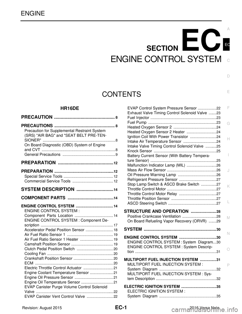
EC-1
ENGINE
C
DE
F
G H
I
J
K L
M
SECTION EC
A
EC
N
O P
CONTENTS
ENGINE CONTROL SYSTEM
HR16DE
PRECAUTION ....... ........................................
8
PRECAUTIONS .............................................. .....8
Precaution for Supplemental Restraint System
(SRS) "AIR BAG" and "SEAT BELT PRE-TEN-
SIONER" ............................................................. ......
8
On Board Diagnostic (OBD) System of Engine
and CVT ....................................................................
8
General Precautions .................................................9
PREPARATION ...........................................12
PREPARATION .............................................. ....12
Special Service Tools .......................................... ....12
Commercial Service Tools ......................................12
SYSTEM DESCRIPTION .............................14
COMPONENT PARTS ................................... ....14
ENGINE CONTROL SYSTEM ............................... ....14
ENGINE CONTROL SYSTEM :
Component Parts Location ....................................
14
ENGINE CONTROL SYSTEM : Component De-
scription ............................................................... ....
17
Accelerator Pedal Position Sensor ..........................18
Air Fuel Ratio Sensor 1 ...........................................19
Air Fuel Ratio Sensor 1 Heater ...............................19
Camshaft Position Sensor .......................................19
Clutch Pedal Position Switch ..................................20
Cooling Fan .............................................................20
Crankshaft Position Sensor .....................................20
ECM .................................................................... ....20
Electric Throttle Control Actuator ............................21
Engine Coolant Temperature Sensor ......................21
Engine Oil Pressure Sensor ....................................21
Engine Oil Temperature Sensor ..............................21
EVAP Canister Purge Volume Control Solenoid
Valve ................................................................... ....
22
EVAP Canister Vent Control Valve .........................22
EVAP Control System Pressure Sensor ..................22
Exhaust Valve Timing Cont rol Solenoid Valve ........23
Fuel Injector ......................................................... ....23
Fuel Pump ...............................................................23
Heated Oxygen Sensor 2 ........................................24
Heated Oxygen Sensor 2 Heater ............................24
Ignition Coil With Power Transistor .........................24
Intake Air Temperature Sensor ...............................24
Intake Valve Timing Control Solenoid Valve ...........25
Knock Sensor ...................................................... ....25
Battery Current Sensor (With Battery Tempera-
ture Sensor) .............................................................
25
Malfunction Indicator Lamp (MIL) ............................26
Mass Air Flow Sensor ..............................................26
Oil Pressure Warning Lamp ....................................26
Refrigerant Pressure Sensor ............................... ....27
Stop Lamp Switch & ASCD Brake Switch ...............27
Throttle Control Motor .......................................... ....27
Throttle Control Motor Relay ...................................27
Throttle Position Sensor ..........................................27
ASCD Steering Switch .............................................27
STRUCTURE AND OPERATION .....................28
Positive Crankcase Ventilation ................................28
On Board Refueling Vapor Recovery (ORVR) ........29
SYSTEM ............................................................30
ENGINE CONTROL SYSTEM ........................ ...........30
ENGINE CONTROL SYSTEM : System Diagram ....30
ENGINE CONTROL SYSTEM : System Descrip-
tion ...........................................................................
31
MULTIPORT FUEL INJECTION SYSTEM ................31
MULTIPORT FUEL INJECTION SYSTEM :
System Diagram ................................................. ....
32
MULTIPORT FUEL INJECTION SYSTEM : Sys-
tem Description ........................................................
32
ELECTRIC IGNITION SYSTEM .................................35
ELECTRIC IGNITION SYSTEM :
System Diagram ................................................. ....
35
Revision: August 2015 2016 Versa Note
cardiagn.com
Page 1130 of 3641

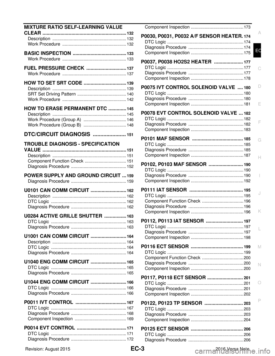
EC-3
C
DE
F
G H
I
J
K L
M
EC A
N
O P
MIXTURE RATIO SELF-LEARNING VALUE
CLEAR ............................................................ ..
132
Description .......................................................... ..132
Work Procedure ....................................................132
BASIC INSPECTION ........................................133
Work Procedure .................................................. ..133
FUEL PRESSURE CHECK ..............................137
Work Procedure .................................................. ..137
HOW TO SET SRT CODE ................................139
Description .......................................................... ..139
SRT Set Driving Pattern ........................................140
Work Procedure ....................................................142
HOW TO ERASE PERMANENT DTC ..............145
Description .......................................................... ..145
Work Procedure (Group A) ...................................146
Work Procedure (Group B) ...................................148
DTC/CIRCUIT DIAGNOSIS .......................151
TROUBLE DIAGNOSIS - SPECIFICATION
VALUE ............................................................ ..
151
Description .......................................................... ..151
Component Function Check ..................................151
Diagnosis Procedure .............................................152
POWER SUPPLY AND GROUND CIRCUIT ....159
Diagnosis Procedure ........................................... ..159
U0101 CAN COMM CIRCUIT ...........................162
Description .......................................................... ..162
DTC Logic .............................................................162
Diagnosis Procedure .............................................162
U0284 ACTIVE GRILLE SHUTTER .................163
DTC Logic ........................................................... ..163
Diagnosis Procedure .............................................163
U1001 CAN COMM CIRCUIT ...........................164
Description .......................................................... ..164
DTC Logic .............................................................164
Diagnosis Procedure .............................................164
U1040 ENG COMM CIRCUIT ...........................165
DTC Logic ........................................................... ..165
Diagnosis Procedure .............................................165
U1044 ENG COMM CIRCUIT ...........................166
DTC Logic ........................................................... ..166
Diagnosis Procedure .............................................166
P0011 IVT CONTROL ......................................167
DTC Logic ........................................................... ..167
Diagnosis Procedure .............................................168
Component Inspection ..........................................169
P0014 EVT CONTROL .....................................171
DTC Logic .............................................................171
Diagnosis Procedure .............................................172
Component Inspection ......................................... ..173
P0030, P0031, P0032 A/F SENSOR HEATER .174
DTC Logic ............................................................ ..174
Diagnosis Procedure .............................................174
Component Inspection ...........................................175
P0037, P0038 HO2S2 HEATER .....................177
DTC Logic ..............................................................177
Diagnosis Procedure .............................................177
Component Inspection ...........................................178
P0075 IVT CONTROL SOLENOID VALVE ....180
DTC Logic ..............................................................180
Diagnosis Procedure .............................................180
Component Inspection ...........................................181
P0078 EVT CONTROL SOLENOID VALVE ...182
DTC Logic ..............................................................182
Diagnosis Procedure .............................................182
Component Inspection ...........................................183
P0101 MAF SENSOR .....................................185
DTC Logic ..............................................................185
Diagnosis Procedure .............................................185
Component Inspection ...........................................187
P0102, P0103 MAF SENSOR .........................190
DTC Logic ..............................................................190
Diagnosis Procedure .............................................190
Component Inspection ...........................................192
P0111 IAT SENSOR .......................................195
DTC Logic ..............................................................195
Component Function Check ..................................196
Diagnosis Procedure .............................................196
Component Inspection ...........................................196
P0112, P0113 IAT SENSOR ...........................197
DTC Logic ..............................................................197
Diagnosis Procedure .............................................197
Component Inspection ...........................................198
P0116 ECT SENSOR ......................................199
DTC Logic ..............................................................199
Component Function Check ..................................200
Diagnosis Procedure .............................................200
Component Inspection ...........................................200
P0117, P0118 ECT SENSOR ..........................201
DTC Logic ..............................................................201
Diagnosis Procedure .............................................201
Component Inspection ...........................................202
P0122, P0123 TP SENSOR ............................203
DTC Logic ..............................................................203
Diagnosis Procedure .............................................203
Component Inspection ...........................................204
P0125 ECT SENSOR ......................................206
DTC Logic ..............................................................206
Diagnosis Procedure .............................................206
Revision: August 2015 2016 Versa Note
cardiagn.com
Page 1131 of 3641

EC-4
Component Inspection ...........................................207
P0127 IAT SENSOR ........................................208
DTC Logic ............................................................ ..208
Diagnosis Procedure .............................................208
Component Inspection ...........................................209
P0128 THERMOSTAT FUNCTION .................210
DTC Logic ............................................................ ..210
Diagnosis Procedure .............................................211
Component Inspection ...........................................212
P0130 A/F SENSOR 1 .....................................213
DTC Logic ............................................................ ..213
Component Function Check ..................................214
Diagnosis Procedure .............................................214
P0131 A/F SENSOR 1 .....................................217
DTC Logic ............................................................ ..217
Diagnosis Procedure .............................................218
P0132 A/F SENSOR 1 .....................................220
DTC Logic ............................................................ ..220
Diagnosis Procedure .............................................221
P0137 HO2S2 ..................................................223
DTC Logic ............................................................ ..223
Component Function Check ..................................224
Diagnosis Procedure .............................................225
Component Inspection ...........................................226
P0138 HO2S2 ..................................................229
DTC Logic ............................................................ ..229
Component Function Check ..................................230
Diagnosis Procedure .............................................231
Component Inspection ...........................................234
P0139 HO2S2 ..................................................237
DTC Logic ............................................................ ..237
Component Function Check ..................................238
Diagnosis Procedure .............................................239
Component Inspection ...........................................240
P014C, P014D, P015A, P015B, A/F SENSOR
1 .......................................................................
243
DTC Logic ............................................................ ..243
Diagnosis Procedure .............................................245
P0171 FUEL INJECTION SYSTEM FUNC-
TION .................................................................
248
DTC Logic ............................................................ ..248
Diagnosis Procedure .............................................249
P0172 FUEL INJECTION SYSTEM FUNC-
TION .................................................................
252
DTC Logic ............................................................ ..252
Diagnosis Procedure .............................................253
P0181 FTT SENSOR .......................................256
DTC Logic ............................................................ ..256
Component Function Check ................................ .257
Diagnosis Procedure .............................................258
Component Inspection ..........................................259
P0182, P0183 FTT SENSOR ............................260
DTC Logic ............................................................ .260
Diagnosis Procedure .............................................260
Component Inspection ..........................................261
P0196 EOT SENSOR .......................................262
DTC Logic .............................................................262
Component Function Check .................................264
Diagnosis Procedure .............................................264
Component Inspection ..........................................264
P0197, P0198 EOT SENSOR ...........................265
DTC Logic ............................................................ .265
Diagnosis Procedure .............................................265
Component Inspection ..........................................266
P0222, P0223 TP SENSOR ..............................267
DTC Logic .............................................................267
Diagnosis Procedure .............................................267
Component Inspection ..........................................268
P0300, P0301, P0302, P0303, P0304 MIS-
FIRE ..................................................................
270
DTC Logic ............................................................ .270
Diagnosis Procedure .............................................271
P0327, P0328 KS .............................................276
DTC Logic ............................................................ .276
Diagnosis Procedure .............................................276
Component Inspection ..........................................277
P0335 CKP SENSOR (POS) ............................278
DTC Logic ............................................................ .278
Diagnosis Procedure .............................................278
Component Inspection ..........................................280
P0340 CMP SENSOR (PHASE) .......................282
DTC Logic ............................................................ .282
Diagnosis Procedure .............................................282
Component Inspection ..........................................284
P0420 THREE WAY CATALYST FUNCTION ..285
DTC Logic ............................................................ .285
Component Function Check .................................286
Diagnosis Procedure .............................................287
P0441 EVAP CONTROL SYSTEM ..................290
DTC Logic .............................................................290
Component Function Check .................................291
Diagnosis Procedure .............................................292
P0443 EVAP CANISTER PURGE VOLUME
CONTROL SOLENOID VALVE ........................
295
DTC Logic ............................................................ .295
Diagnosis Procedure .............................................296
Component Inspection .........................................
Revision: August 2015 2016 Versa Note
cardiagn.com
Page 1132 of 3641

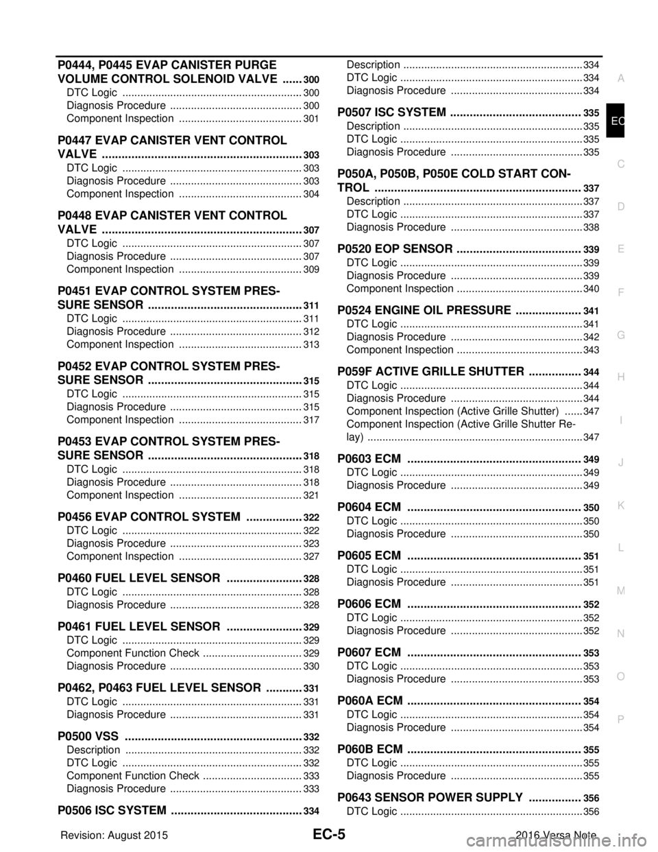
EC-5
C
DE
F
G H
I
J
K L
M
EC A
N
O P
P0444, P0445 EVAP CANISTER PURGE
VOLUME CONTROL SOLENOID VALVE ..... ..
300
DTC Logic ........................................................... ..300
Diagnosis Procedure .............................................300
Component Inspection ..........................................301
P0447 EVAP CANISTER VENT CONTROL
VALVE ..............................................................
303
DTC Logic ........................................................... ..303
Diagnosis Procedure .............................................303
Component Inspection ..........................................304
P0448 EVAP CANISTER VENT CONTROL
VALVE ..............................................................
307
DTC Logic ........................................................... ..307
Diagnosis Procedure .............................................307
Component Inspection ..........................................309
P0451 EVAP CONTROL SYSTEM PRES-
SURE SENSOR ................................................
311
DTC Logic ........................................................... ..311
Diagnosis Procedure .............................................312
Component Inspection ..........................................313
P0452 EVAP CONTROL SYSTEM PRES-
SURE SENSOR ................................................
315
DTC Logic ........................................................... ..315
Diagnosis Procedure .............................................315
Component Inspection ..........................................317
P0453 EVAP CONTROL SYSTEM PRES-
SURE SENSOR ................................................
318
DTC Logic ........................................................... ..318
Diagnosis Procedure .............................................318
Component Inspection ..........................................321
P0456 EVAP CONTROL SYSTEM ..................322
DTC Logic ........................................................... ..322
Diagnosis Procedure .............................................323
Component Inspection ..........................................327
P0460 FUEL LEVEL SENSOR ........................328
DTC Logic ........................................................... ..328
Diagnosis Procedure .............................................328
P0461 FUEL LEVEL SENSOR ........................329
DTC Logic ........................................................... ..329
Component Function Check ..................................329
Diagnosis Procedure .............................................330
P0462, P0463 FUEL LEVEL SENSOR ............331
DTC Logic ........................................................... ..331
Diagnosis Procedure .............................................331
P0500 VSS .......................................................332
Description .......................................................... ..332
DTC Logic .............................................................332
Component Function Check ..................................333
Diagnosis Procedure .............................................333
P0506 ISC SYSTEM .........................................334
Description ........................................................... ..334
DTC Logic ..............................................................334
Diagnosis Procedure .............................................334
P0507 ISC SYSTEM ........................................335
Description .............................................................335
DTC Logic ..............................................................335
Diagnosis Procedure .............................................335
P050A, P050B, P050E COLD START CON-
TROL ...............................................................
337
Description .............................................................337
DTC Logic ..............................................................337
Diagnosis Procedure .............................................338
P0520 EOP SENSOR ......................................339
DTC Logic ..............................................................339
Diagnosis Procedure .............................................339
Component Inspection ...........................................340
P0524 ENGINE OIL PRESSURE ....................341
DTC Logic ..............................................................341
Diagnosis Procedure .............................................342
Component Inspection ...........................................343
P059F ACTIVE GRILLE SHUTTER ................344
DTC Logic ..............................................................344
Diagnosis Procedure .............................................344
Component Inspection (Active Grille Shutter) .......347
Component Inspection (Active Grille Shutter Re-
lay) ....................................................................... ..
347
P0603 ECM .....................................................349
DTC Logic ..............................................................349
Diagnosis Procedure .............................................349
P0604 ECM .....................................................350
DTC Logic ..............................................................350
Diagnosis Procedure .............................................350
P0605 ECM .....................................................351
DTC Logic ..............................................................351
Diagnosis Procedure .............................................351
P0606 ECM .....................................................352
DTC Logic ..............................................................352
Diagnosis Procedure .............................................352
P0607 ECM .....................................................353
DTC Logic ..............................................................353
Diagnosis Procedure .............................................353
P060A ECM .....................................................354
DTC Logic ..............................................................354
Diagnosis Procedure .............................................354
P060B ECM .....................................................355
DTC Logic ..............................................................355
Diagnosis Procedure .............................................355
P0643 SENSOR POWER SUPPLY ................356
DTC Logic ..............................................................356
Revision: August 2015 2016 Versa Note
cardiagn.com