Page 129 of 261

; Differentia llock for the front axle
= Differentia llock for the")
Engaging th
edifferential locks General notes
The switches are at the top of the centre con-
sole. :
Function indicato rlam ps (red)
; Differentia llock for the front axle
= Differentia llock for the transfe rcase
? Differentia llock for the rea raxle
A Activation indicator lamps (yellow)
Engag ethe differential locks:
R off-road
R to deactivate ABS, 4ETS, ESP ®
and BAS when
off-road
R whe nfording
Furthe rinformation on driving off-road
(Y page 119).
You can engage the differential locks in the fol-
lowing order: =,?,;.
Important safety notes G
WARNING
If you engag ethe differential locks when driv-
ing on afirm, high-traction surface, the steer-
ability of the vehicl eisseverely impaired .You
coul dlose control of the vehicle, especially
when activating on abend. There is arisk of an
accident.
Disengage the differential locks immediately
on afirm, high-traction surface. G
WARNING
When the differential locks are engaged, ABS, 4ETS, ESP ®
and BAS are deactivated. This
coul dcauset he wheels to lock and increases the braking distance. There is
ariskofan
accident.
Disengag ethe differential locks immediately
on fir msurfaces with good grip.
! Onl
yengag ethe differential locks when:
R youa redrivin gatw alking pace
R the drive wheels ar enot spinning
R youa renot drivin gonafirmr oads urface
Differential lock fo rthe transfe rcase X
To engage: press switch =.
The yellow indicator lamp under switch =
lights up.
The å warning lamp in the instrument
cluster lights up.
If the differential is locked ,the red function
indicator lamp above switch =lights up.
In the multifunctio ndisplay ,you see the
Differential locks active ABS and Differential locks active ABS and
ESP not available ESP not available
The å!÷ warninglamps light up in
the instrument cluster.
The differential lock for the transfer case is
engaged.
4ETS, ESP ®
,B AS and ABS are deactivated.
Vehicle steerability is severely restricted. Drive
carefully and accelerate gently for optimum
traction.
You can now engage the differential lock for rear axle ?and front axle ;as required.
Differential lockf or the rear axle X
To engage: press switch ?.
Yellow act ivation indicator lamp Alights up
first, followe dbyred functio nindicator
lamp :of switch ?.
The differential lock for the rea raxleis
engaged.
Differential lock for the fron taxle X
To engage: press switch ;.
The yellow activation indicator lamp lights up
first, followe dbythe red functio nindicator
lamp.
The differential lock for the front axl eis
engaged. 126
Off-road driving systemsDriving an
dparking
Page 130 of 261

Disengaging th
ediffere ntial locks You can disengage the differential lock
sinthe
followin gorder: ;,?, =.
X To simultaneously disengage all differen-
tia
llocks: press switch =.
Yellow activatio nindicator lamps Aand red
function indicator lamps :go out.
After approximately three seconds of normal
driving, ABS, 4ETS, ESP ®
and BA Sare activa-
ted.
The Differential lock sactive ABS
Differential lock sactive ABS
and ESP not available
and ESP not available message disap-
pear sint he multifunction displaya nd the
å!÷warnin glamps in th einstru-
men tcluster go out.
X Shif tthe transfer case to the HIGH RANGE
on-road position (Y page 124).
If red function indicator lamps :do not go out
when disengagin gthe differential locks:
X Observe th etraffic situation.
X Make slight steerin gmovements while the
vehicle is in motion.
Red function indicator lamps :go out when
th ed ifferential lock sare disengaged. Towing
atrailer Importan
tsafety notes G
WARNING
Th eb raking system can overheat if you leave
yourf oot on the brake peda lwhile driving.
This increases the braking distance and could
even caus ethe braking system to fail .There is
ar isk of an accident.
Never use the brake peda lasafootrest. Do
not simultaneously depress both the brake
peda land the accelerator peda lwhile driving. G
WARNING
You coul dlose control of the vehicle/trailer
combination if it begins to swerve .The vehi-
cle/trailer combination coul deven overturn.
There is arisk of an accident.
On no account should you attempt to
straighten out the vehicle/trailer combina-
tion by increasing speed. Decrease your speed and do not countersteer. Brake if nec-
essary.
G
WARNING
If the ballc oupling is not fitted correctly and
the bolts supplied are not tightened to the
specified tightening torque ,the trailer could
come loose. There is arisk of an accident.
Always fit the ballc oupling as described.
Observe the specified tightening torque when fitting the coupling. G
WARNING
If the maximu mpermissible loadf orac arrier
system is exceeded, the carrie rcouldc ome
loos efrom the vehicl eand endange rother
road users. There is arisk of an accident and
injury.
Never exceed the maximu mpermissible load
when using acarrier.
! If you have
atrailer tow hitch retrofitted,
changes to the engine cooling system may be necessary, depending on the vehicl etype.
If you have atrailer tow hitch retrofitted,
observe the anchorage points on the chassis.
Retrofitting atrailer tow hitch is only permissible
if at railer loadiss pecified in yourv ehicledocu-
ments. If this is not the case, then the vehicl eis
not approved for towing atrailer.
For more information, please contact aqualified
specialist workshop.
Exceeding the maximu mpermissible nose-
weight of the trailer drawbar on the ballc oupling
may caus edamage.
Damag emay be caused to the following:
R towing vehicle
R trailer
R ballc oupling
R trailer tow hitch
The vehicle/trailer combination coul dbecome
unstable.
The vehicle/trailer combination coul dalso
become unstable if the noseweight used is lower
than the minimu mpermissible noseweight. Towin
gatrailer
127Driving an dparking Z
Page 131 of 261

To avoid hazardous situations:
R make sure to check the noseweight before
each journey
R the noseweight should be as close as possible
to the maximum noseweight
R do not exceed the maximum permissible
noseweight
R the noseweight must not be lower than the
minimum permissible noseweight
Make sure that the following values are not
exceeded:
R the permissible noseweight
R the permissible trailer load
R the permissible rear axle load of the towing
vehicle
R the maximum permissible gross vehicle
weight of both the towing vehicle and the
trailer
When reversin gthe towing vehicle, make sure
there is nobody between the trailer and the vehi- cle.
The applicable permissible values, which must
not be exceeded, can be found:
R in your vehicle documents
R on the type plates for the trailer
R on the vehicle identification plate
If the values differ, the lowest value applies.
You will find the values approved by the manu-
facturer on the identification plates and for the
towing vehicle under "Technical data"
(Y page 256).
When reversin gthe towing vehicle, make sure
there is nobody between the trailer and the vehi- cle.
Couple and uncouple the trailer carefully. If youdo not couple the trailer to the towing vehicle
correctly, the trailer could become detached.
When towing atrailer, your vehicle's handling
characteristics will be different from when driv-
ing without atrailer.
The vehicle/trailer combination:
R is heavier
R is restricted in its acceleration and gradient-
climbing capability
R has an increased braking distance
R is affected more by stron gcrosswinds
R demands more sensitiv esteering
R has alarger turnin gcircle This can impair the vehicle's handling charac-
teristics. Adapt your driving style accordingly.
Maintain asafe distance. Drive carefully.
When towing atrailer, alway sadjust your speed
to the current road and weather conditions. Do
not exceed the maximum permissible speed for
your vehicle/trailer combination. Notes on to
wingatrailer
General notes When towing
atrailer, set the tyre pressure on
the rear axle of the towing vehicle for amaxi-
mum load. Further information on the tyre pres-
sure table in the fuel filler flap (Y page 109).
The height of the ball coupling changes with the load of the vehicle. If necessary, use atrailer
with aheight-adjustable drawbar.
You will find permissible trailer loads under
"Technical data" (Y page 256).
Driving tips X
Observe the information on ESP ®
trailer sta-
bilisation (Y page 55).
X On long and steep downhill gradients, select
shift range 1,2or 3(Y page 105) in good time.
X If necessary, shift the transfer case to LOW
RANGE (Ypage 124).
This will use the braking effect of the engine, so less braking will be required to maintain
the vehicle speed. This relieves the load on
the brake system and prevents the brakes
from overheating and wearing too quickly. If
you need additional braking, depress the
brake pedal repeatedly rather than continu-
ously.
The maximum permissible speed for vehicle/
trailer combinations depends on the type of
trailer. Before beginnin gthe journey, check the
trailer's documents to see what the maximum
permitted speed is. Observe the maximum per-
missible speed in the relevant country.
For certain Mercedes-Benz vehicles, the maxi-
mum permissibler ear axle load is increased
when towing atrailer. See the "Technical data"
section to find out whether this applies to your
vehicle (Y page 256). In the event of increased
rear axle load, the car/trailer combination may
not exceed amaximum speed of 100 km/h for
reasons concerning the operating permit. This 128
Towing
atrailerDriving and parking
Page 132 of 261

also applies in countries in whic
hthe maximum
permissible spee dfor car/trailer combinations
is greate rtha n1 00 km/h.
When towing atrailer, your vehicle's handling
characteristics will be differen ttowhen driving
without atrailer and th evehicle will consume
mor efuel.
Driving tips R
Maintain agreater distance to the vehicle in
front than when driving without atrailer.
R Avoid braking abruptly. If possible, brake gen-
tly at first to allow the trailer to run on. Then,
increase the braking force rapidly.
R The values given for gradient-climbing capa-
bilities from astandstill refer to sea level.
When driving in mountainous areas, note that
the power output of the engine, and conse-
quently the vehicle's gradient-climbing capa-
bility from astandstill, decrease with increas-
ing altitude.
If the trailer swings from side to side:
X Do not accelerate under any circumstances.
X Do not countersteer.
X Brake, if necessary. Coupling up
atrailer
! Do no
tconnect th etrailer brak esystem (if
th et railer is fitte dwitho ne)d irectly to the
towing vehicle's hydraulic brak esystem,
since this is equipped wit hananti-lock brak-
ing system. Otherwise, neither th ebrakes on
th et ow ing vehicle no rthe brakes on the
trailer will work.
Observ ethe maximum permissible trailer
dimension s(widt hand length).
X Apply th evehicle's parking brake.
X Mak esure that th eautomatic transmission is
in transmission position P.
X Positio nthe trailer on aleve lsurface behind
th ev ehicle.
X Couple up th etrailer.
X Establish th eelectrical connection between
th ev ehicle and th etrailer.
X Chec kthatthe trailer lighting system is work-
ing.
X Push th ecombinatio nswitch upward sand
downwards and check whether th ecorre- sponding tur
nsignal indicator on the trailer is
flashing.
Ac onnected trailer is only detected when the
electrical connection is established correctly
and when the lighting system is working prop-
erly. The function of other systems, such as
ESP ®
also depends on this. Uncoupling
atrailer G
WARNING
If you uncouple atrailer with an engaged over-
run brake, you coul dtrap yourh and between
the vehicl eand the trailer drawbar. This poses
ar isk of injury.
Do not uncouple atrailer with an engaged
overru nbrake.
! Do not disconnect
atrailer with an engaged
overru nbrake. Otherwise, yourv ehiclecould
be damaged by the rebounding of the overrun brake.
X Apply the parking brake.
X Make sure that the automatic transmission is
in transmission position P.
X Secure the vehicl eand trailer against rolling
away.
X Close all doors, including the rear door.
X Remove the trailer cable.
X Uncoupl ethe trailer. Traile
rpower supply
! Yo
uc an connect accessories with amaxi-
mu mp ower consumption of 180 Wtothe
permanent powe rsupply.
Yo um ustn ot charge atrailer battery using the
powe rsupply.
The trailer socket of your vehicl eisequippe dat
the factory with apermanent powe rsupply.
The permanent powe rsuppl yiss upplie dvia
trailer socket pi n9.
Yo uc an find mor einformatio nabout installing
the trailer electrics at aquali fied specialis twork-
shop. Towin
gatrailer
129Driving an dparking Z
Page 133 of 261
Trailer with 7-pi
nconnect or
General notes Trailer with 7-pi
nconnect or:youc an connect
to the 13-pi nsocke tont he ball coupling using
an adapter or, if necessary ,anadapter cable.
Both can be obtained at aquali fied specialist
workshop.
Fittin gthe adapter !
Mak
esure that there is sufficient cable play
so that the cable cannot become detached
when cornering. X
Open the socket cover.
X Insert the connector with lug :into
groove ;on the socket and turn it clockwise
to the stop.
X Let the cover engage.
X If you are using an adapter cable, secure the
cable to the trailer with cable ties. 130
Towing
atrailerDriving and parking
Page 134 of 261

Important safety notes
G
WARNING
Operating th eintegrated information systems
and communications equipment in the vehicle
while driving willd istract you from traffic con-
ditions. You coul dthen lose control of the
vehicle. There is arisk of an accident.
Only operate these devices if road traffic con-
ditions permit. If you are unsure about the
surrounding conditions, pullo ver toasafe
location and make entries only while the vehi-
cle is stationary.
You must observe the lega lrequirements for the
country in which you are currently driving when operating the on-board computer. G
WARNING
If the instrument cluster has failed or mal-
functioned, you may not recognise function
restrictions relevant to safety .The operating
safety of yourv ehiclemay be impaired .There
is ar isk of an accident.
Drive on carefully.H ave the vehiclechecked
at aq ualified specialist worksho pimmedi-
ately.
If the operating safety of yourv ehicleis
impaired ,park the vehicl esafel yass oon as pos-
sible. Contact aqualified specialist workshop.
! If
ab lackout lighting setting has been selec-
ted, the instrument cluster lighting is
switched off.
The instrument cluster and the display do not show any information.
The on-board computer show sonly display mes-
sage sorw arnings from certain systems on the
multifunction display.Y ou should therefore
make sure yourv ehicleiso perating safel yatall
times.
For an overview, see the instrument cluster illus-
tration (Y page26). Displays and operation
Instrument cluste
rlighting
The brightness control knob is locate donthe
botto mleftoft heinstrumen tcluster
(Y page 26).
X Turn th ebrightness control knob clockwise or
anti-clockwise.
i The ligh
tsensor on th einstrumen tcluster
automatically control sthe brightness of the
multifunction display.
In daylight, th edisplays in th einstrument
cluste rare no tlit. Re
vc ounter
! Do not drive in the overrevving range. Doing
so will damag ethe engine.
The red band in the rev counter indicates the
engine's overrevving range.
The fue lsuppl yisi nterrupted to protect the
engine when the red band is reached. Outside temperature display
You should pay specia lattention to road condi-
tion swhen temperatures are around freezing
point.
Bear in mind that the outside temperature dis-
play indicates the measured air temperature
and not the road surface temperature.
The outside temperature display is in the multi-
function display (Y page 133).
Changes in the outside temperature are dis-
played after ashort delay. Coolant temperatur
edisplay G
WARNING
If yo uopen the bonnet while the engine is
overheating or while there is afire in the
engine compartment, you coul dcome into
contact with hot gase sorother leaking ser-
vice products. There is adange rofinjury.
Allow an overheating engine to cool down
before opening the bonnet. If there is afire in Displays and operation
131On-boardcomputer and displays
Z
Page 135 of 261
.
Under normal operating cond")
the engine compartment, leav
ethe bonnet
close dand notify the fir ebrigade.
The coolant temperatur egauge is in the instru-
ment cluste ronthe right-hand side (Y page 26).
Under normal operating conditions and with the specifie dcoolant level ,the coolant temperature
ma yriseto1 20 †.
At high outside temperatures and when driving
in mountainou sterrain, the coolant temperature
ma yrisetot he end of the scale. Operatin
gthe on-board computer
Overview :
Multifunction display
; Switches sound on/off
= Right control panel
? Left control panel
A Back button
X To activate the on-board computer: turn
the key to position 1in the ignition lock
(Y page 96).
You can control the multifunction display and
the settings in the on-board computer using the buttons on the multifunction steering wheel. Left control panel =
; R
Calls up the menu and menu bar 9
: Press briefly:
R Scrolls through lists
R Selects asubmenu or function
R In the Audio Audio menu: selects the
previous or next station, when the preset list or station list is active,
or an audio track
R In the Tel Tel(telephone) menu:
switches to the phone book and
selects aname or telephone num-
ber 9
: Press and hold:
R
In the Audio Audio menu: selects apre-
set list or astation list in the
desired frequency range a R
Confirms selection/displaym es-
sage
R In the Tel
Tel(Telephone) menu:
switches to th etelephone book
and start sdiallin gthe selected
number Right contro
lpanel ~ R
Rejects or end sacall 6 R
Makes or accept sacall
R Switches to the redial memory W
X R
Adjusts the volume 8 R
Mute ? R
Mute 132
Displays and operationOn-board computer and displays
Page 136 of 261

Back button
% Press briefly:
R Back
R Hides displa ymessages/calls up
the last Trip
Tripmenu function used
R Exitst he telephone book/redial
memory % Press and hold:
R Callsupt he standard display in the
Trip
Trip menu Multifunction display
:
Transmission position (Y page 101)
; Drive program (Y page 104)
= Text field
? Menu bar
A Time (Y page 138)
B Outside temperature or speed
(Ypage 137)
C Transfer case position (Y page 124)
X To display menu bar?:p ress the=
or ; button on the steerin gwheel.
If you do not press the button sany longer,
menu bar ?is faded out after afew seconds.
Text field =shows the selected menu or sub-
menu and display messages. The following messages may appear in the mul-
tifunction display:
Z Gearshift recommendation
(Ypage 106)
è ECO start/stopf unction (Ypage 97)
LOW LOW
RANGE RANGE Transfer case position (Y
page 124)
ë HOLD function (Y page 122) Menu
sand submenus Menu overview
Press the =or; button on the steering
whee ltoopen the menu bar.
Operating the on-board compute r(Ypag e132).
Depending on the equipment fitted in the vehi-
cle, you can call up the following menus:
R Trip Trip menu (Y page133)
R Navi
Navi menu (navigatio ninstructions)
(Y pag e134)
R Audio
Audio menu (Y page135)
R Tel
Tel menu (telephone) (Y page136)
R Serv.
Serv. menu (Y page137)
R Settings
Settings menu (settings) (Y page137) Trip menu
Standard display X
Pres sand hold the %button on the steer-
ing wheel until the Trip
Tripmenu with trip
meter :and total distanc erecorder ;
appears. Menu
sand submenus
133On-boardcomputer and displays Z
 1
1 2
2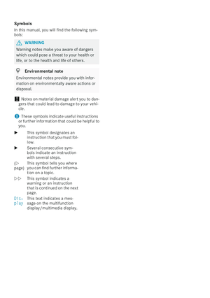 3
3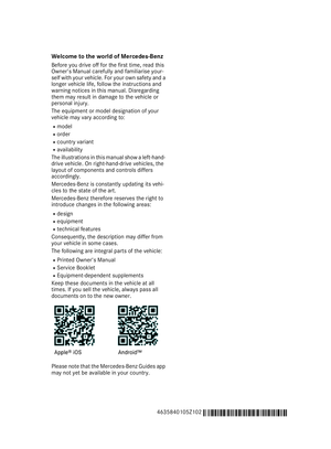 4
4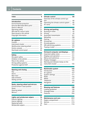 5
5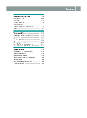 6
6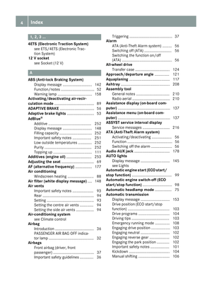 7
7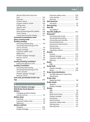 8
8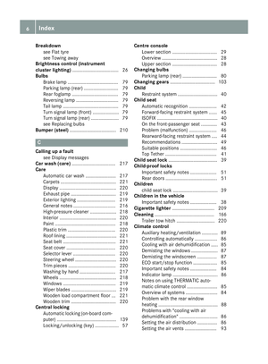 9
9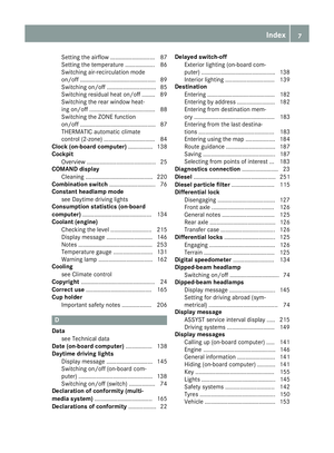 10
10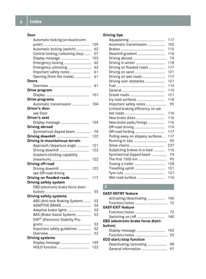 11
11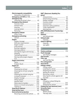 12
12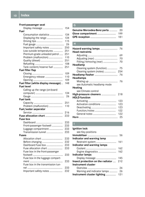 13
13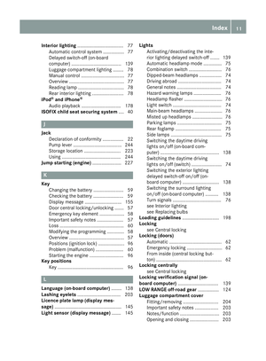 14
14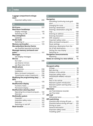 15
15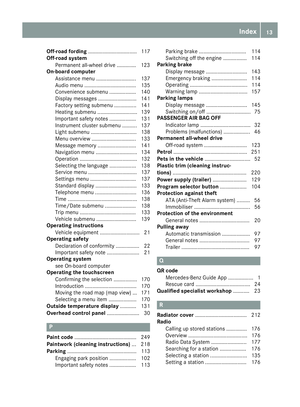 16
16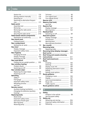 17
17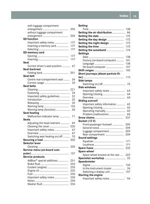 18
18 19
19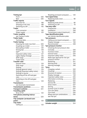 20
20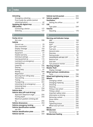 21
21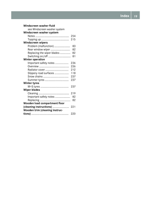 22
22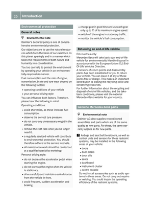 23
23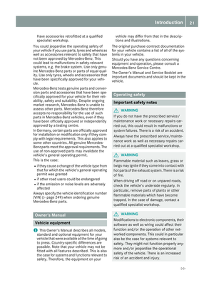 24
24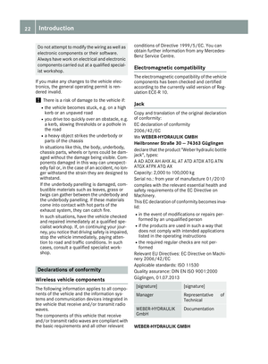 25
25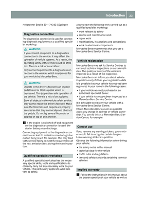 26
26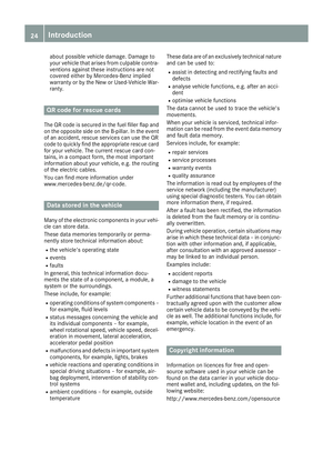 27
27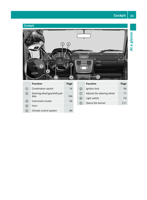 28
28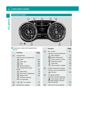 29
29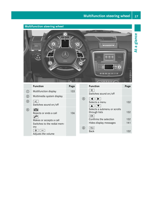 30
30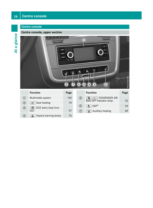 31
31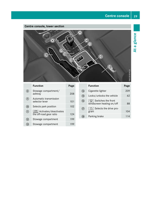 32
32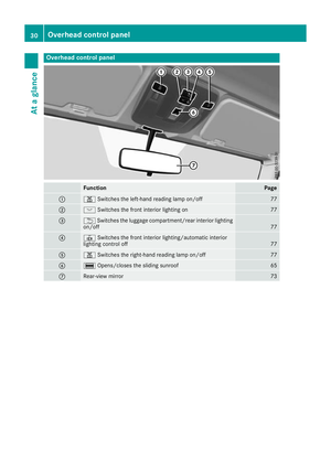 33
33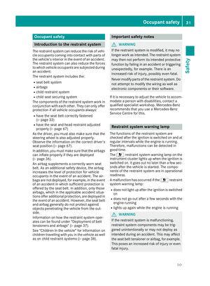 34
34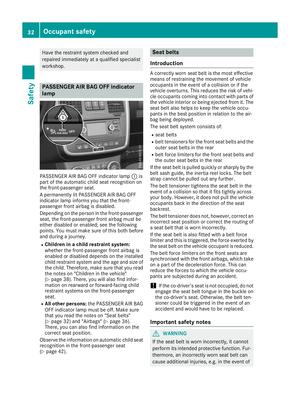 35
35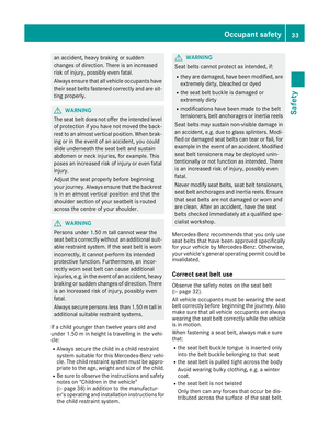 36
36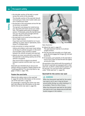 37
37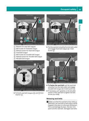 38
38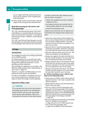 39
39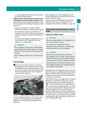 40
40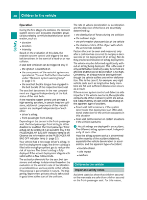 41
41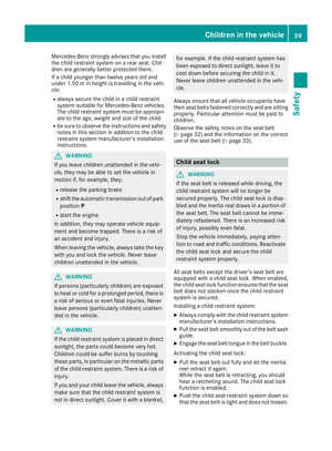 42
42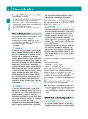 43
43 44
44 45
45 46
46 47
47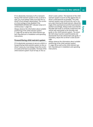 48
48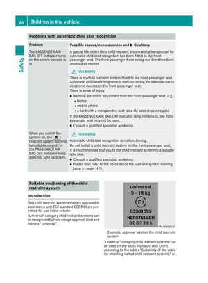 49
49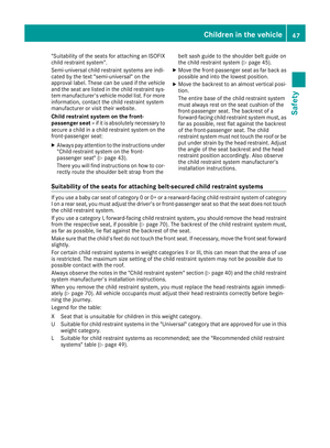 50
50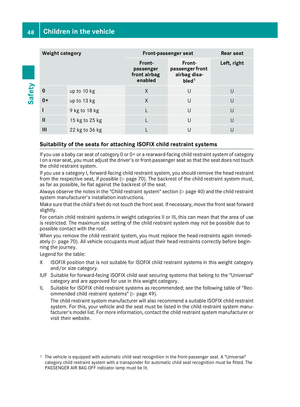 51
51 52
52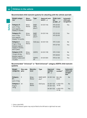 53
53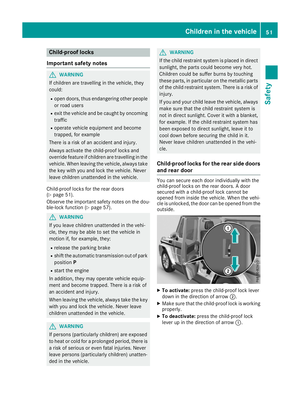 54
54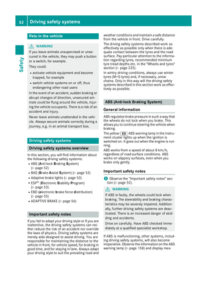 55
55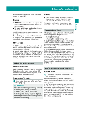 56
56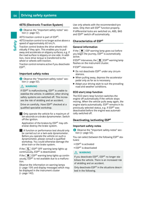 57
57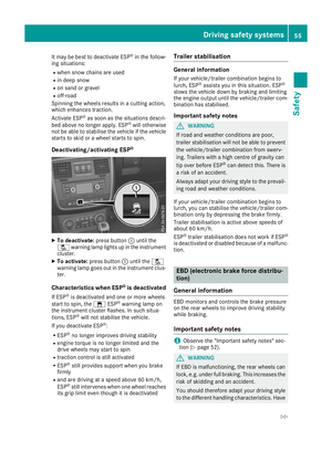 58
58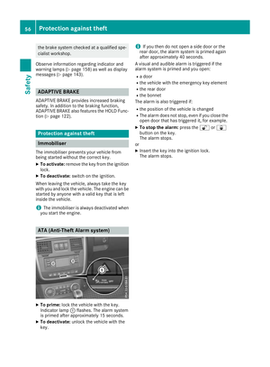 59
59 60
60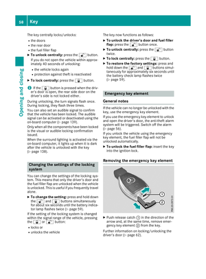 61
61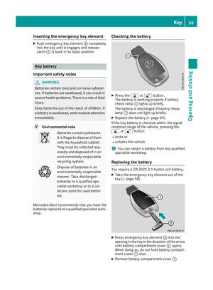 62
62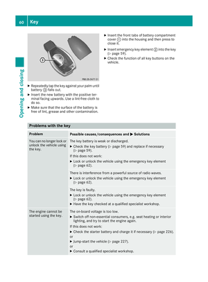 63
63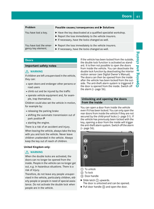 64
64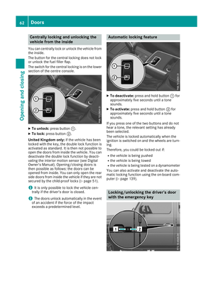 65
65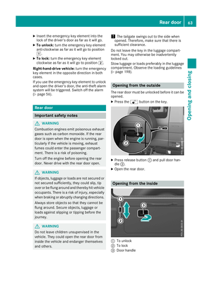 66
66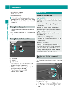 67
67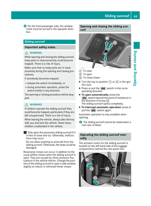 68
68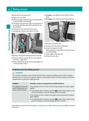 69
69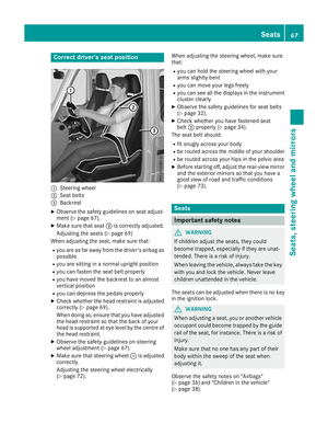 70
70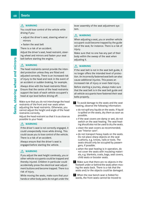 71
71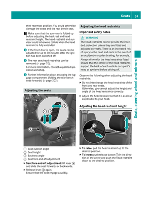 72
72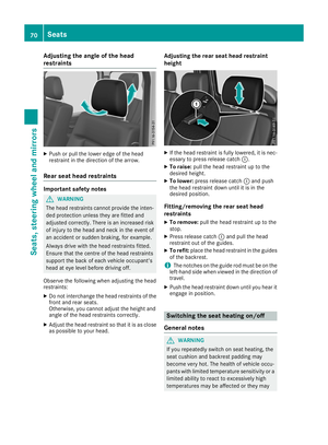 73
73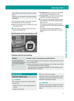 74
74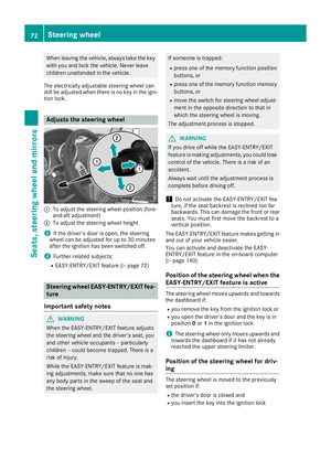 75
75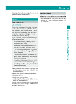 76
76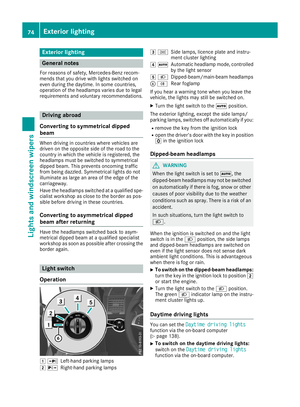 77
77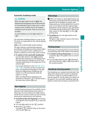 78
78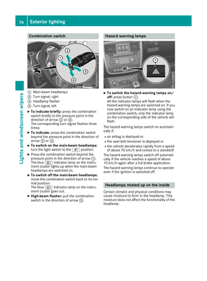 79
79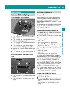 80
80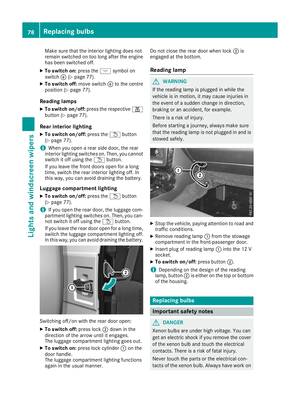 81
81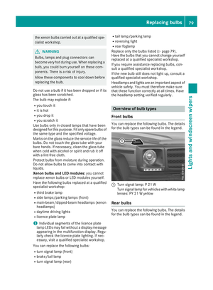 82
82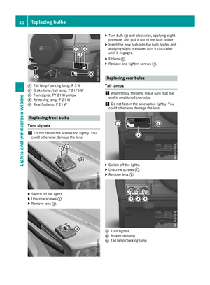 83
83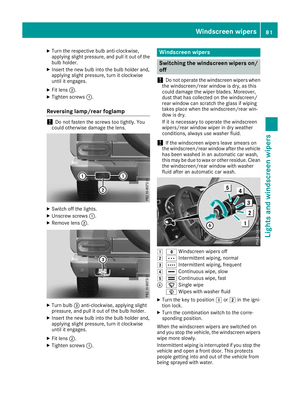 84
84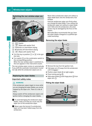 85
85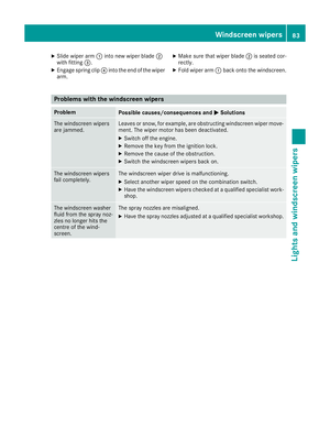 86
86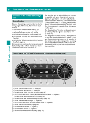 87
87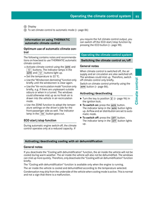 88
88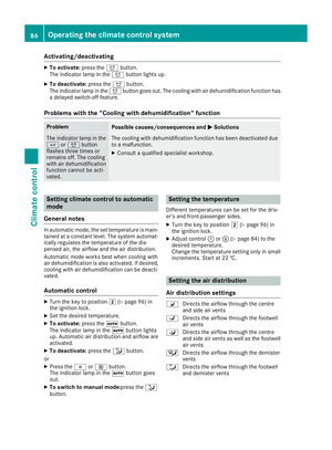 89
89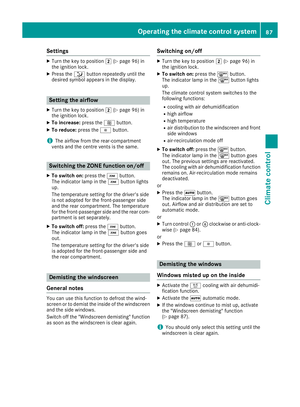 90
90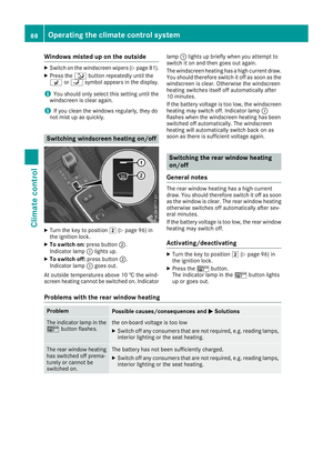 91
91 92
92 93
93 94
94 95
95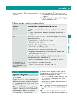 96
96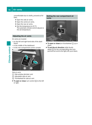 97
97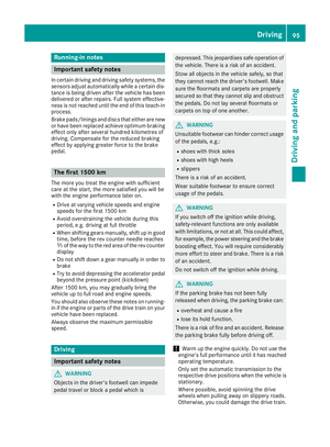 98
98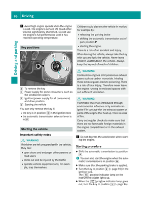 99
99 100
100 101
101 102
102 103
103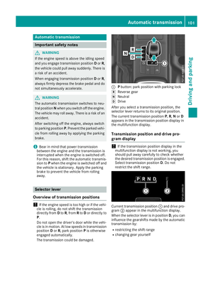 104
104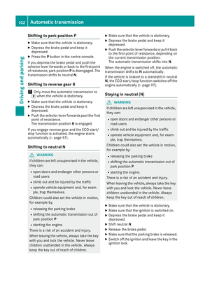 105
105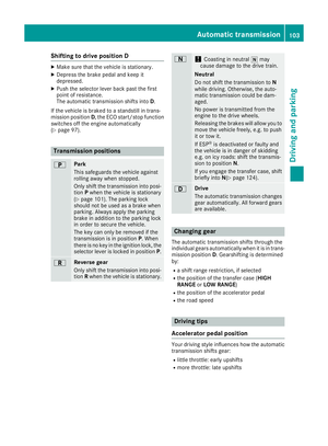 106
106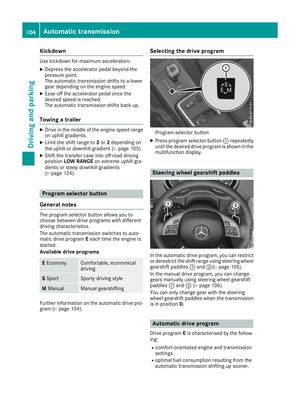 107
107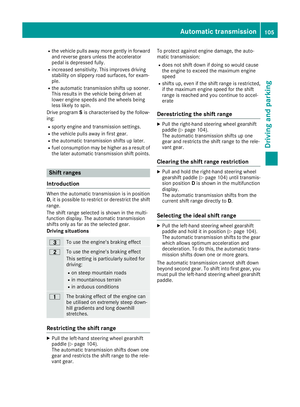 108
108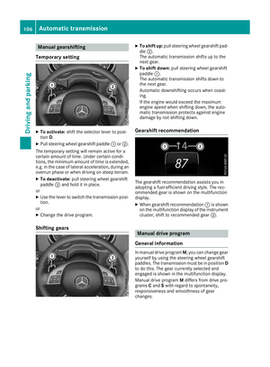 109
109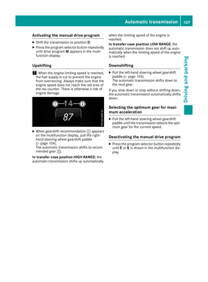 110
110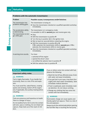 111
111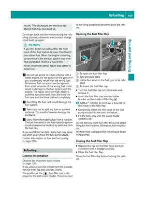 112
112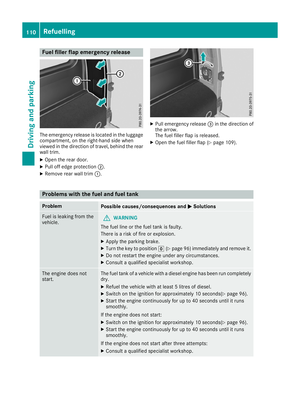 113
113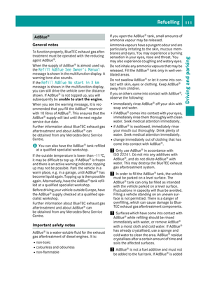 114
114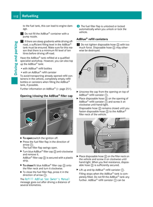 115
115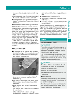 116
116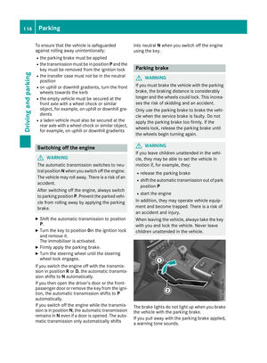 117
117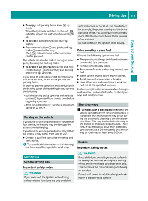 118
118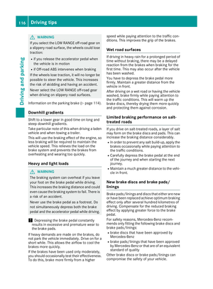 119
119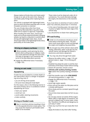 120
120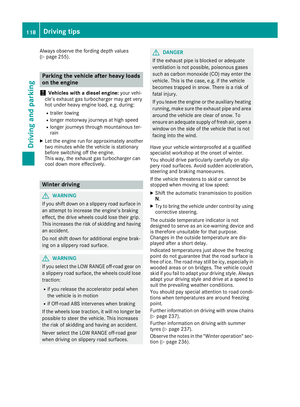 121
121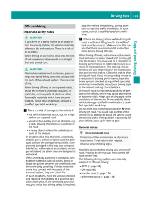 122
122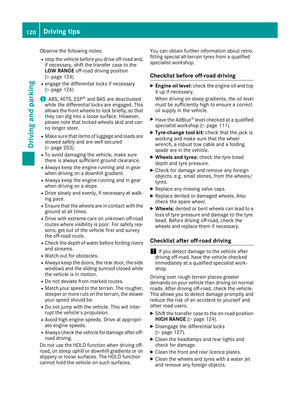 123
123 124
124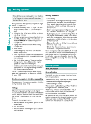 125
125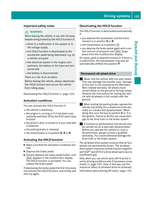 126
126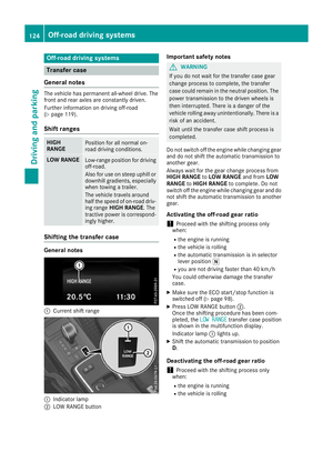 127
127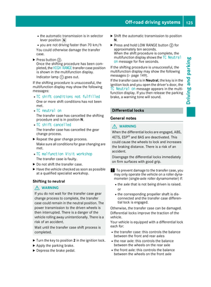 128
128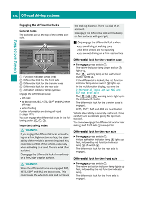 129
129 130
130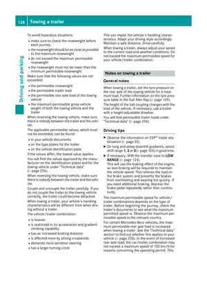 131
131 132
132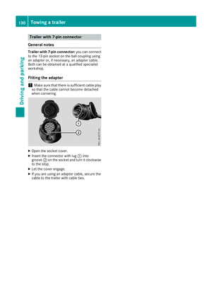 133
133 134
134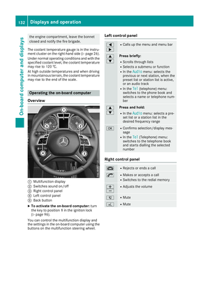 135
135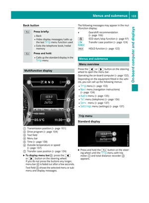 136
136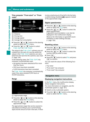 137
137 138
138 139
139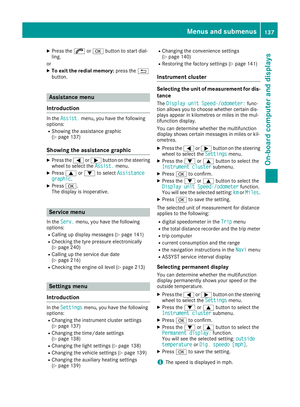 140
140 141
141 142
142 143
143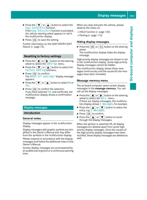 144
144 145
145 146
146 147
147 148
148 149
149 150
150 151
151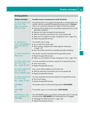 152
152 153
153 154
154 155
155 156
156 157
157 158
158 159
159 160
160 161
161 162
162 163
163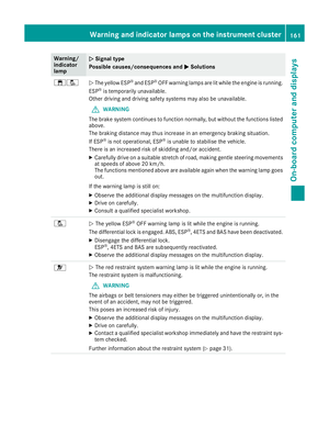 164
164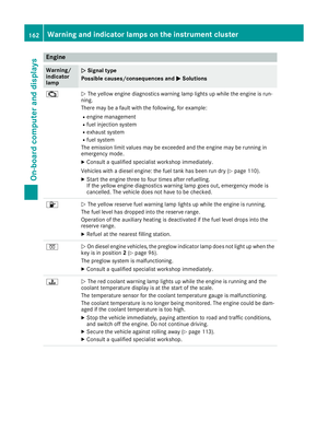 165
165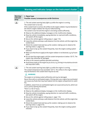 166
166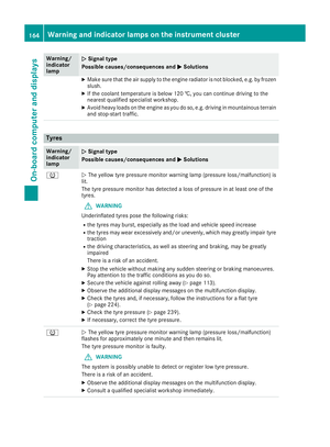 167
167 168
168 169
169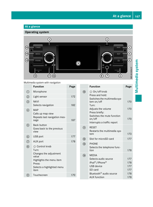 170
170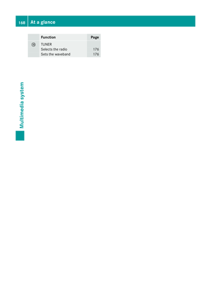 171
171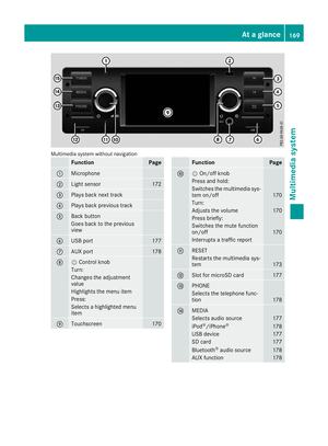 172
172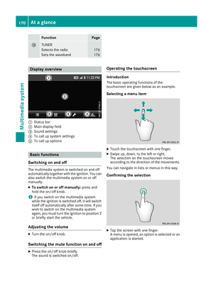 173
173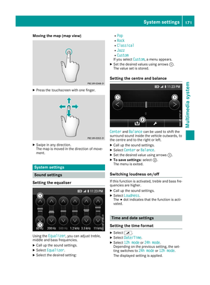 174
174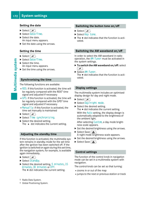 175
175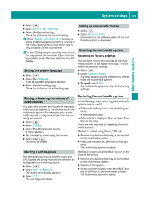 176
176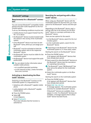 177
177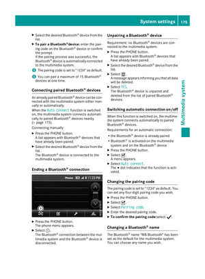 178
178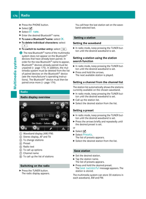 179
179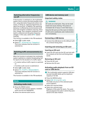 180
180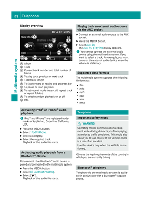 181
181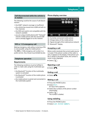 182
182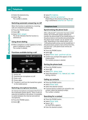 183
183 184
184 185
185 186
186 187
187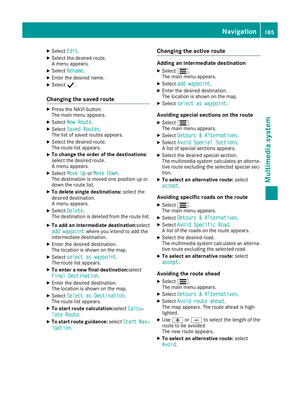 188
188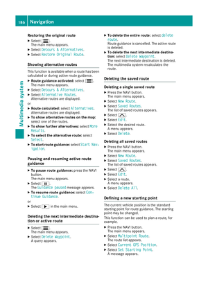 189
189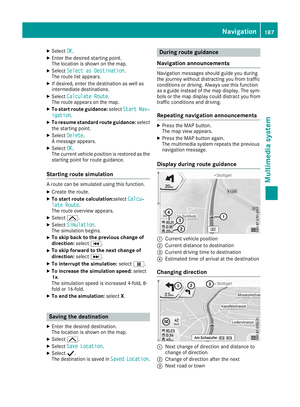 190
190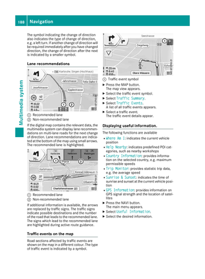 191
191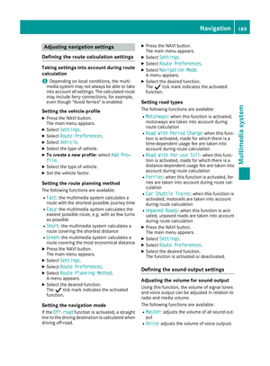 192
192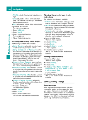 193
193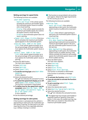 194
194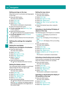 195
195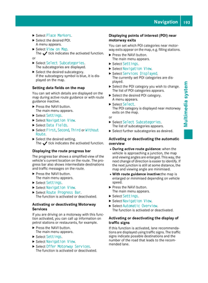 196
196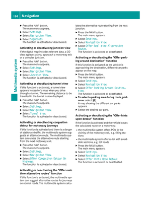 197
197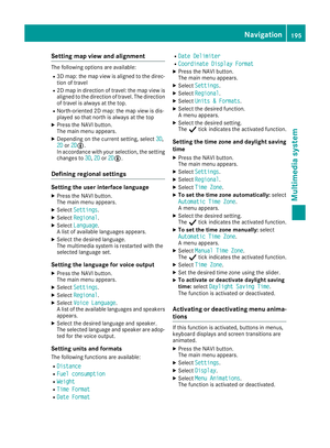 198
198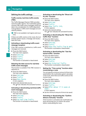 199
199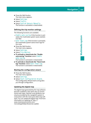 200
200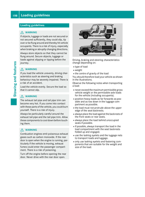 201
201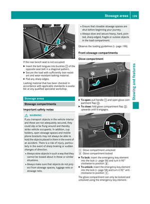 202
202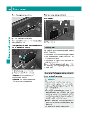 203
203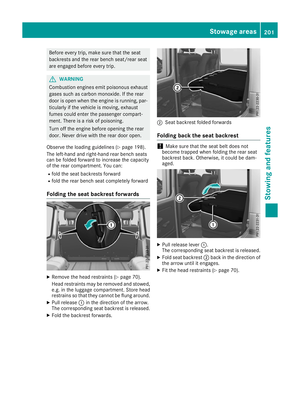 204
204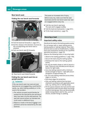 205
205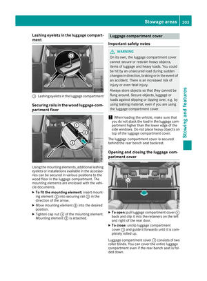 206
206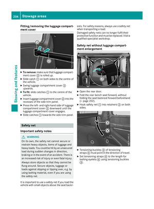 207
207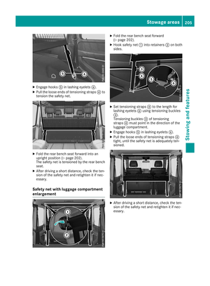 208
208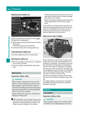 209
209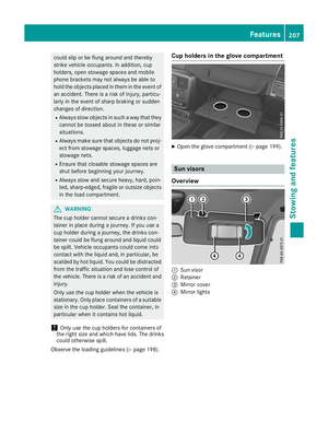 210
210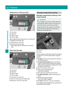 211
211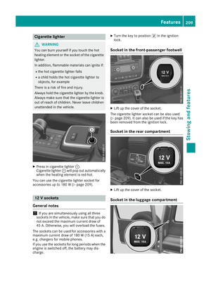 212
212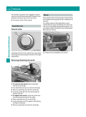 213
213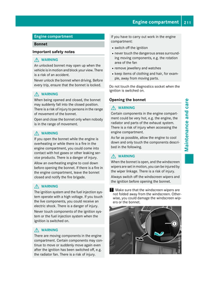 214
214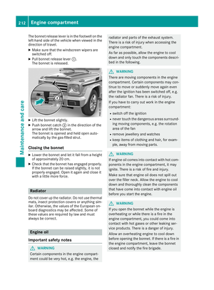 215
215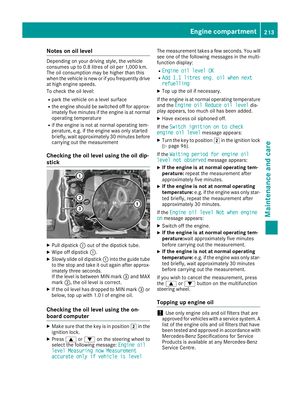 216
216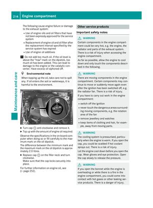 217
217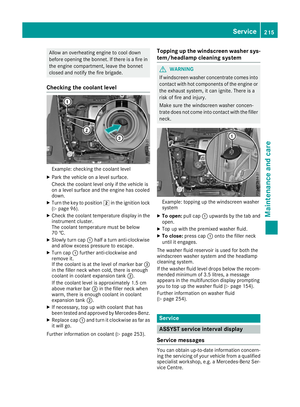 218
218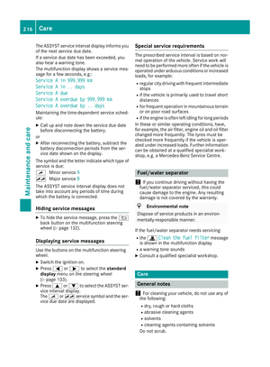 219
219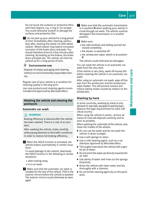 220
220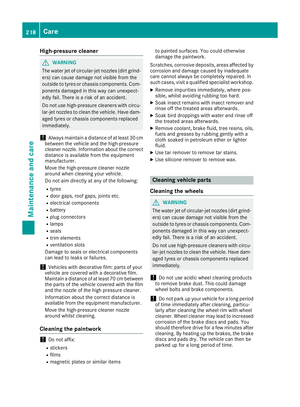 221
221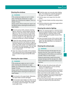 222
222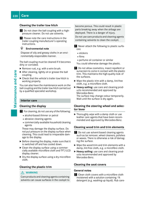 223
223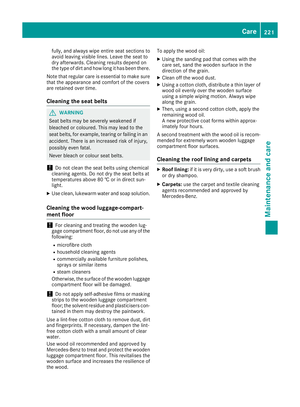 224
224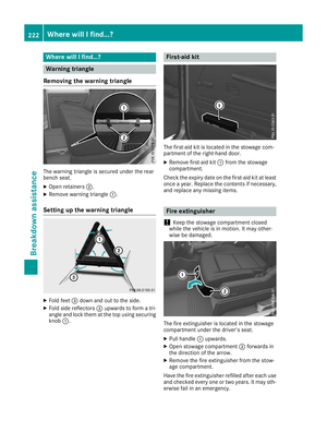 225
225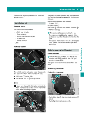 226
226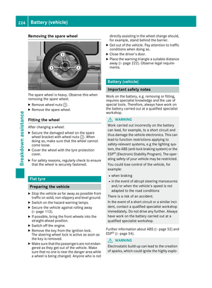 227
227 228
228 229
229 230
230 231
231 232
232 233
233 234
234 235
235 236
236 237
237 238
238 239
239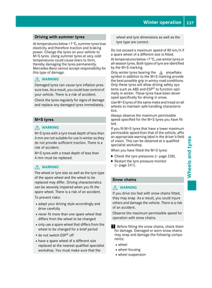 240
240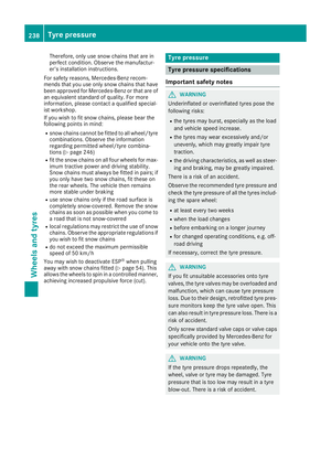 241
241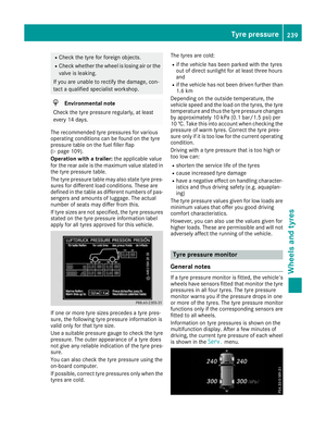 242
242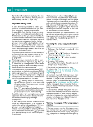 243
243 244
244 245
245 246
246 247
247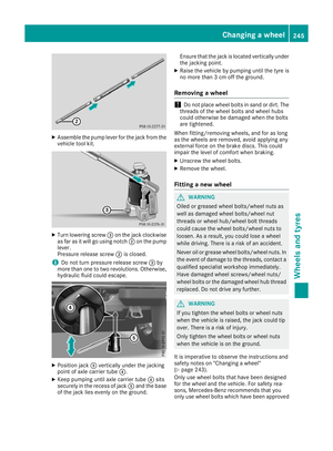 248
248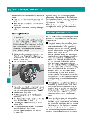 249
249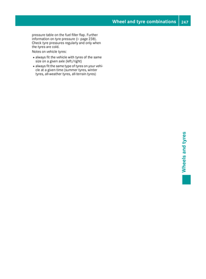 250
250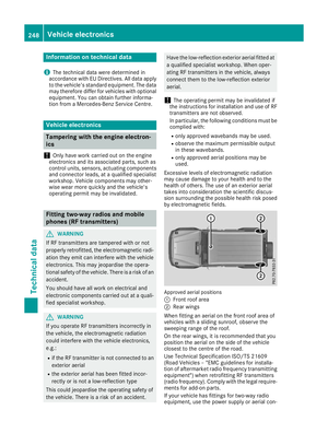 251
251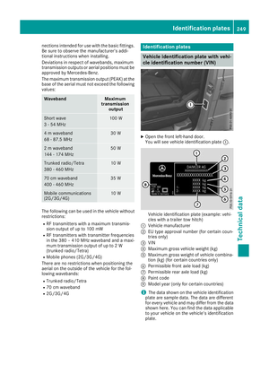 252
252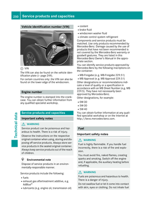 253
253 254
254 255
255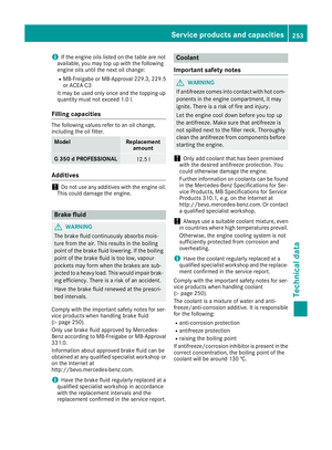 256
256 257
257 258
258 259
259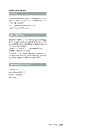 260
260