2016 MERCEDES-BENZ G-CLASS SUV length
[x] Cancel search: lengthPage 132 of 261

also applies in countries in whic
hthe maximum
permissible spee dfor car/trailer combinations
is greate rtha n1 00 km/h.
When towing atrailer, your vehicle's handling
characteristics will be differen ttowhen driving
without atrailer and th evehicle will consume
mor efuel.
Driving tips R
Maintain agreater distance to the vehicle in
front than when driving without atrailer.
R Avoid braking abruptly. If possible, brake gen-
tly at first to allow the trailer to run on. Then,
increase the braking force rapidly.
R The values given for gradient-climbing capa-
bilities from astandstill refer to sea level.
When driving in mountainous areas, note that
the power output of the engine, and conse-
quently the vehicle's gradient-climbing capa-
bility from astandstill, decrease with increas-
ing altitude.
If the trailer swings from side to side:
X Do not accelerate under any circumstances.
X Do not countersteer.
X Brake, if necessary. Coupling up
atrailer
! Do no
tconnect th etrailer brak esystem (if
th et railer is fitte dwitho ne)d irectly to the
towing vehicle's hydraulic brak esystem,
since this is equipped wit hananti-lock brak-
ing system. Otherwise, neither th ebrakes on
th et ow ing vehicle no rthe brakes on the
trailer will work.
Observ ethe maximum permissible trailer
dimension s(widt hand length).
X Apply th evehicle's parking brake.
X Mak esure that th eautomatic transmission is
in transmission position P.
X Positio nthe trailer on aleve lsurface behind
th ev ehicle.
X Couple up th etrailer.
X Establish th eelectrical connection between
th ev ehicle and th etrailer.
X Chec kthatthe trailer lighting system is work-
ing.
X Push th ecombinatio nswitch upward sand
downwards and check whether th ecorre- sponding tur
nsignal indicator on the trailer is
flashing.
Ac onnected trailer is only detected when the
electrical connection is established correctly
and when the lighting system is working prop-
erly. The function of other systems, such as
ESP ®
also depends on this. Uncoupling
atrailer G
WARNING
If you uncouple atrailer with an engaged over-
run brake, you coul dtrap yourh and between
the vehicl eand the trailer drawbar. This poses
ar isk of injury.
Do not uncouple atrailer with an engaged
overru nbrake.
! Do not disconnect
atrailer with an engaged
overru nbrake. Otherwise, yourv ehiclecould
be damaged by the rebounding of the overrun brake.
X Apply the parking brake.
X Make sure that the automatic transmission is
in transmission position P.
X Secure the vehicl eand trailer against rolling
away.
X Close all doors, including the rear door.
X Remove the trailer cable.
X Uncoupl ethe trailer. Traile
rpower supply
! Yo
uc an connect accessories with amaxi-
mu mp ower consumption of 180 Wtothe
permanent powe rsupply.
Yo um ustn ot charge atrailer battery using the
powe rsupply.
The trailer socket of your vehicl eisequippe dat
the factory with apermanent powe rsupply.
The permanent powe rsuppl yiss upplie dvia
trailer socket pi n9.
Yo uc an find mor einformatio nabout installing
the trailer electrics at aquali fied specialis twork-
shop. Towin
gatrailer
129Driving an dparking Z
Page 207 of 261

Fitting/removing th
eluggage compart-
men tcover X
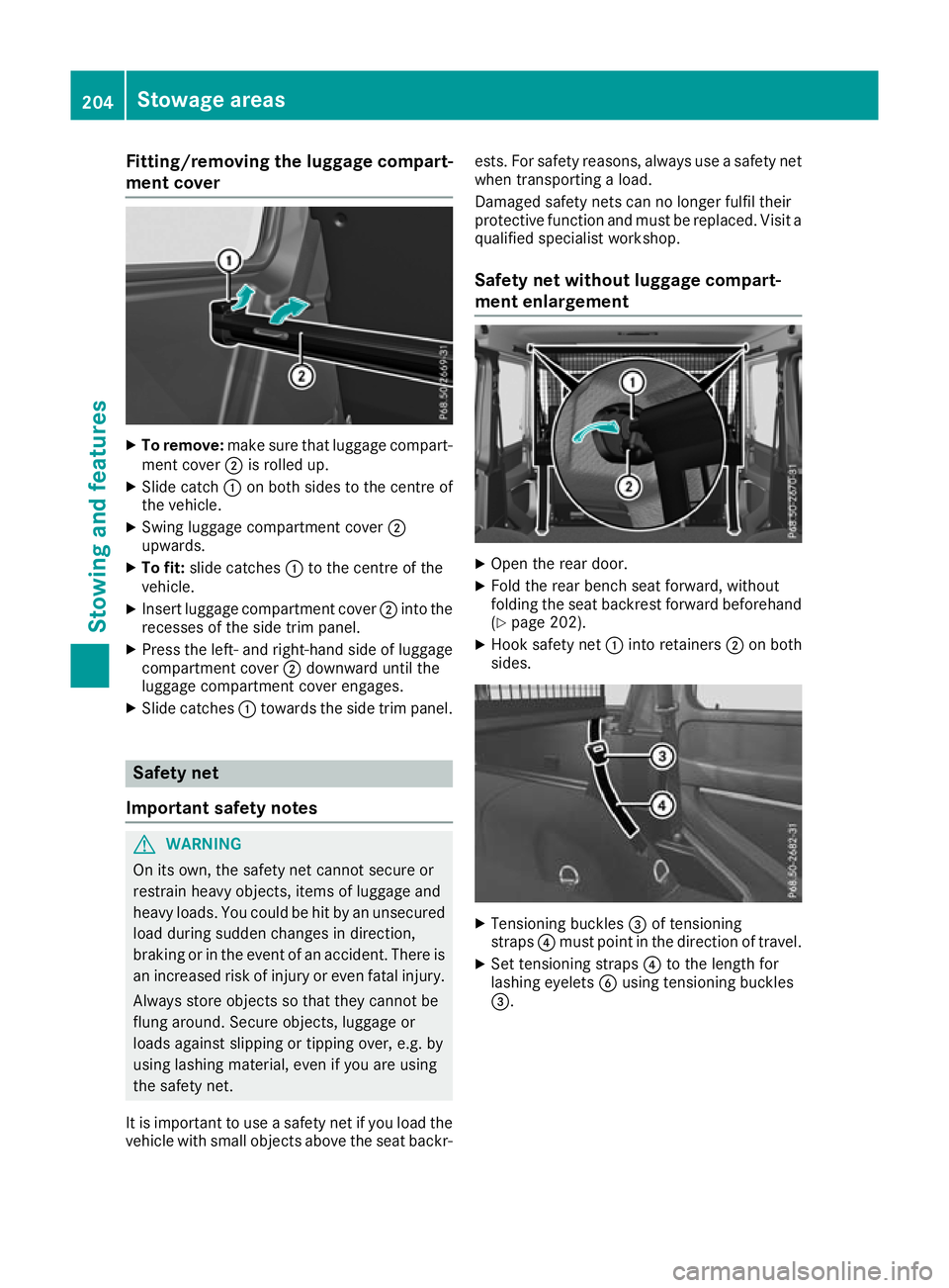
To remove: makesuret ha tlug gage compart-
ment cover ;is rolle dup.
X Slide catch :on both side stothe centre of
the vehicle.
X Swing luggage compartment cover ;
upwards.
X To fit: slidecatches :to the centre of the
vehicle.
X Insert luggage compartment cover ;into the
recesse softhe side trim panel.
X Press the left- and right-hand side of luggage
compartment cover ;downward unti lthe
luggage compartment cove rengages.
X Slide catches :toward sthe side trim panel. Safety net
Important safety notes G
WARNING
On its own, the safet ynet cannot secure or
restrai nheavy objects, items of luggage and
heavy loads. You coul dbehit by an unsecured
loadd uring sudden changes in direction,
braking or in the event of an accident. There is an increased risk of injury or even fatal injury.
Always store objects so that they cannot be
flung around. Secure objects, luggage or
loads against slipping or tipping over, e.g. by
using lashing material, even if you are using
the safety net.
It is important to use asafety net if you loadt he
vehicl ewith smal lobjects above the seat backr- ests
.For safety reasons, alway suseasafety net
when transporting aload.
Damaged safety netsc an no longer fulfil their
protective function and must be replaced. Visit a qualified specialist workshop.
Safet ynet without luggage compart-
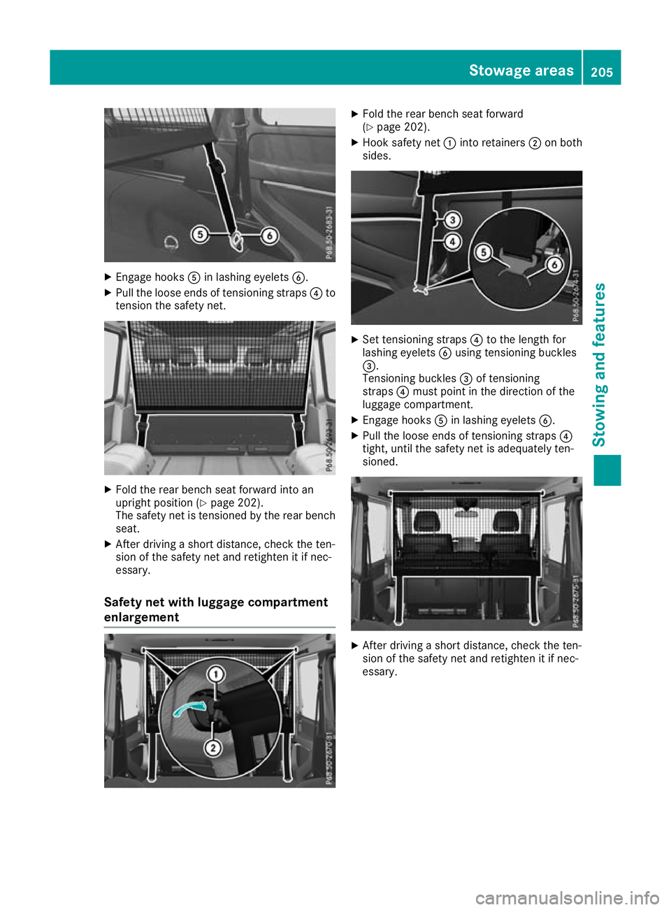
ment enlargement X
Open the rear door.
X Fold the rear bench seat forward, without
folding the seat backrest forward beforehand
(Y page 202).
X Hook safety net :into retainers ;on both
sides. X
Tensionin gbuckles =of tensioning
straps ?must point in the direction of travel.
X Set tensioning straps ?to the length for
lashing eyelets Busing tensioning buckles
=. 204
Stowage areasStowing and features
Page 208 of 261

X
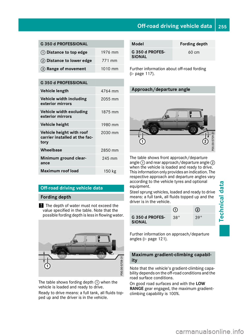
Engage hooks Ain lashing eyelets B.
X Pull the loose end softensioning straps ?to
tensio nthe safety net. X
Fold the rea rbench sea tforward into an
upright positio n(Ypage 202).
The safety net is tensioned by the rea rbench
seat.
X After driving ashor tdistance, check the ten-
sio noft he safety net and retighten it if nec-
essary.
Safety ne twithl uggag ecom partment
enlargement X
Fold the rea rbench sea tforward
(Y page 202).
X Hook safety net :into retainers ;on both
sides. X
Set tensioning straps ?to the length for
lashing eyelets Busing tensioning buckles
=.
Tensioning buckles =of tensioning
straps ?mus tpoint in the direction of the
luggage compartment.
X Engag ehooks Ain lashing eyelets B.
X Pull the loose ends of tensioning straps ?
tight, unti lthe safety net is adequately ten-
sioned. X
After driving ashort distance, check the ten-
sion of the safety net and retighte nitifnec-
essary. Stowag
eareas
205Stowing and features Z
Page 258 of 261

G3
50dPROFESSIONAL :
Distance to to pedge 1976 mm
;
Distanc etolower edge 77
1mm =Rang
eofmovement 1010 mm
G3
50dPROFESSIONAL Vehicl
elength 4764 mm
Vehicl
ewidth including
exterior mirrors 2055 mm
Vehicl
ewidth excluding
exterior mirrors 1875 mm
Vehicl
eheight 1980 mm
Vehicl
eheight with roof
carrier installe datthe fac-
tory 2030 mm
Wheelbase
2850 mm
Minimum ground clear-
ance
245 mm
Maximum roof load
150 kg
Off-road driving vehicl
edata Fording depth
! The depth of water must not exceed the
values pecifiedinthetable. Not ethatthe
possible fordin gdept hisl ess in flowin gwater. The tabl
eshows fording depth :when the
vehicle is loaded and ready to drive.
Ready to drive means: afull tank,a ll fluids top-
ped up and the driver is in the vehicle. Model Fording depth
G3
50dPROFES-
SIONAL 60 cm
Further information abouto
ff-roadfording
(Y page 117). Approach/departure angle
The table shows front approach/departure
angle
:and rea rapproach/departure angle ;
when the vehicle is loaded and ready to drive.
This information only provides an indication .The
respective approach and departure angles vary
according to the vehicle tyres and optional
equipment.
Steel sprung vehicles, loaded and ready to drive
means: afull tank,a ll fluids topped up and the
driver is in the vehicle. : : ;
;
G3
50dPROFES-
SIONAL 38° 39°
Further information on approach/departure
angles (Y
page 121). Maximum gradient-climbing capabil-
ity
Note that the vehicle's gradient-climbing capa-
bility depends on the off-road conditions and the
road surface conditions.
On good road surfaces and with the LOW
RANGE gear engaged, the maximu mgradient-
climbing capability is 100%. Off-roa
ddriving vehicle data
255Technical data Z