Page 25 of 244

Trip computer
Introduction
The trip computer gives you information on
current and average fuel mileage, average
speed, fuel range and driving time .
Fig. 8 T rip comp ute r 1
The fo llow ing informa tion is cont inuo usly
eva luated by the trip compu ter and can be dis
p layed sequentia lly in the instrument cl uster
d isplay:
Fuel range
The estimated c ruising ra nge in miles (km)
appears in the d isplay . The disp lay changes in
increments of 5 miles (10 km) .
Average fuel mileage
The average fue l economy in MPG (l/ 100 km)
since you last clea red the memory appears in
t his display .
Current fuel mileage
The instantaneous fuel consumption in miles
pe r gallon (l/ 100 km) is shown in this d isp lay .
When the ve hicle is stationary, the most re
cent fuel consumpt io n is displayed.
Average speed
The average speed in mph (km/h) since the
last time the display was reset appears i n the
d isp lay.
Elap sed t ime
The length of time that you have been driving
since you las t reset the memory appears in
this display . The maximum t ime period that
can be recorded is 999 ho urs and 59 minutes .
Driver in formation system 23
Distance
The elapsed dis tance sin ce the las t time the
memory was cleared appears in the d isp lay .
T he maxim um distance that can be recorded
is 9 ,999.9 miles (9,999 .9 k ilometers) .
(D Tips
- Fuel consump tions (average and cur
rent), range and speed are disp layed in
metric un its on Canadian mode ls.
- All sto red val ues wil l be lost if t he vehi
cle battery is d isconnected .
' . Memories
The trip computer is equipped with two fully
automatic memories as well as on efficiency
progrom.
Fi g. 9 Trip co mputer d isplay: memo ry level 1
You can switch between the trip computer 1
and 2 and the efficiency program* by pressing
the
I R ES ET I button @ c::> page 24, fig . 10 .
You can tell wh ich memory leve l is currently
active by the number or the sign in the display
c::> fig . 9. The data from the single-trip memo
ry (memo ry level 1) is being displayed if a
1
appea rs i n t he display . If a 2 is shown, then
the data from the total- trip memory is being
displayed (memory level 2). The f ue l pump
nozzle
ii indicates the efficiency program *
c::>poge 27.
Single-trip memory (Trip computer 1 )
The sing le -t rip memory stores the tr ip info r
ma tion from the time the ig nition is tu rned on
u nt il it is tur ned off. If the tr ip is cont inued
within 2 hour s from the time the ignit ion was
turned off, the new data will be included in ..,.
Page 26 of 244

24 Driver information system
the calculation of the current trip informa
t ion. If the trip is interrupted for
more than 2
hours
the memory is reset automatica lly.
Total -trip memory (Trip computer 2)
Unlike the sing le-trip memory, the total-trip
memory is not reset automatically. This per
mits you to evaluate your dr iving data for the
entire period between manual resets.
Efficiency program*
The effic ien cy program can help you to use
less fuel
~ page 2 7.
Operation
The trip computer is controlled by two
switches on the windshield wiper lever.
-----------< @
Fig. 10 W iper arm/w iper lever: con tro ls for t he trip
compute r
Selecting the trip computer
"Tap the I Reset I button @ until the trip com
puter (memory level 1 or 2) appears in the
display ¢
page 23, fig . 8.
Selecting the functions
" Push in the upper (lower) protrusion on the
function selector switch @
q fig. 10. The
functions for the trip computer are d is
played in succession on the respective mem
ory levels.
Resetting the function to zero
" Push the I Reset I button @ for at least two
seconds.
You can reset the fo llowing values to zero us
ing the
I Reset I button :
- driving time -
distance
- average f uel mileage
- average speed
The t rip computer only operates when the ig
nition is on. When you turn on the ignition,
the function that was in use when you last
turned the ignition off will be displayed .
(D Tips
-You can also set the values for the func
tions to zero in the menu display
(Reset )
qpage24 .
-All stored values will be lost if the vehi
cle battery is disconnected .
- The driving information in the efficiency
program is a lso reset to zero with the
single-trip memory.
Menu display
Introduction
Display Type
•set
iF'Cf t -,,., ==
Menu off
Fig. 11 D isplay: Sta rt men u
Some funct ions in yo ur vehicle can be set , ac
t ivated, and controlled by
Menus (e.g. Acous
tic park assist *). With these menus you can al
so select the information shown in the driver
information system, which operates only with
the ignition switched on. Operation is control
led by the
! Reset I button and the rocker switch
on the wiper lever
q page 25, fig . 12.
The Start menu shows you the different dis
play types
q fig . 11 . Each display type in the
Start menu contains a submenu with addi
tional options .
Page 27 of 244
 ¢
page 25")
Set Clock ¢ page 2 5
Computer¢ page 25
Acoustic par k assist* ¢ page 79
Speed warning ¢ page 77
Language ¢
page 2 5
Units (distance, fue l consump-
tion, temperature) ¢
page 25
Tire press ure moni toring
c> page 198
Lap timer* c>page 28
Lighting* ¢ page 48
Wiper (service pos it io n)
¢page 56
Window c> page 40
Doors (unlo ck ing and locking
mode, for example Auto- lock)
¢ page 34, c> page 34
Check
Service c> page 28
Chassis numbe r c> page 2 22
Engine oil temperature*
¢
page 26, c> page 26
Registe red keys ¢ page 32
Menu off
All of the messages shown in
vehicles withou t menu display ap-
pe ar o n the display screen.
Navigating the menu
Use the rocker switch on the windshield wiper
lever and the
I Reset ! button to operate the
menu and carry out inquiries and selections.
~-- @
Fig. 1 2 Wiper leve r: Controls for the men u disp lay
To open the menu
.. Press the I Reset ! button @ until the menu
display
i=> page 24 , fig . 11 appears
Dr iver in formation system 25
Selections and settings
.. Press the rocker switch @to reac h a men u
disp lay. The swi tch is operated the same as
the display (up/down).
Entering and confirming
.,. Press the I Reset I butto n @ .
Returning to the Start menu
.. Press the I Reset I button longer tha n 2 sec
onds to return from any menu level to the
Sta rt menu .
U sing the rocker switc h, you can select the
menus in the display or change settings. A
cursor appea rs on the left in front of these
lected values .
By pressing the
I Reset! button, you activate
the selection you made or confirm the values
you set.
Selected fu nctions are identified wit h
a check mark or ar e car ried out directly .
Selecting settings
Fig. 13 D isplay: Menu Sett ings, co mpute r selected
(page
l)
Se lect you r settings a s foll ows:
.,. Press the
I Reset I butto n. The Sta rt menu ap
pears ¢
page 24 , fig . 11 .
.. Press the rocker switch unt il Set is dis
played .
.. Press the
I Reset I butto n. All the menu s a p
pe a r .
.. Press the rocker switch until the desire d line
is highlig hted (curso r)
¢ fig . 13 .
.. Press the I Reset I button.
.. If necessary, scro ll by selecting and activat
ing the symbol for "Next page" o r "Previous
page" .
~
Page 28 of 244

26 Driver information system
When you have selected the Computer menu
and activated it by pressing the
I Reset! but
ton, two computer levels appear (computer 1
and computer 2). Now you have to select the
level you want using the rocker switch and ac
tivate it w ith the
! Reset I button .
Engine oil temperature display
Applies to vehicles: with engine temperature control dis
play
Engine oil
Temperature
176 °F
•Back
Fig. 14 Display: engine o il temperature d isp lay
• With the ign ition sw itched on, press the
N
"' l!! a'.. 0) (D
I RESET I button¢ page 24, fig. 10 repeated
ly until the engine oil temperature display is
shown.
The engine has reached its operating temper
ature when the engine oil temperature is be
tween
176 °F (80 °C) and 248 °F (120 °C) un
der normal driving conditions. The engine oil
temperature may be higher if there is heavy
engine load and high temperatures outside.
This is not a cause for concern as long as the
• ¢
page 16 or Ill¢ page 19 warn ing light
in the display does not flash.
Boost and engine oil temperature
indicator
Applies to vehicles: with boost pressure indicator
0 /xi 0
;;i OJ
Fig. 15 Display: boost and engine oi l temperature indi·
ca tor
• With the ignition switched on, press the
button -arrow· repeatedly until the display
is shown.
Boost pressure indicator (boost)
A bar graph that begins on the left and fills in
toward the right indicates the eng ine's c ur
rent load (meaning the current boost pres
s ur e).
Engine oil temperature indicator
If the engine oil temperature is below 140 °F
(60 °C), the
"t::?1 symbol followed by three hy
phens"- --" and the °C unit is shown .
The engine has reached its operating temper
ature when the engine oil temperature is be
tween
176 °F (80 °() and 248 °F (120 °() un
der normal driving conditions. The engine oil
temperature may be higher if there is heavy
engine load and high temperatures outside.
This is not a cause for concern as long as the
• ¢page 16 orl'I c::;,page 19 warning light
in the display does not flash.
Page 29 of 244

Efficiency program
Description
Applies to vehicles: with trip computer with efficiency
program
• 95
!'4 . FM 1
[JI 300 m,
27.7 m pg
25.8 mpg
Fig. 16 Di.splay : effic ie ncy program
.,. Press the I RESET I button@¢ page 24,
fig. 10 repeatedly until the efficiency pro
gram appears in the display .
The eff ic iency p rogram can help yo u to use
l ess fuel.
It eva luates driving information in
reference to fue l cons umption and shows oth
er equipment influencing consumption as we ll
as shift recommendations. F ue l economy
messages ¢
page 27 provide tips for effi
cient dr iv ing .
T he eff iciency program uses distance and con
sumpt ion data from tr ip comp uter
l. If the
data are deleted in the eff iciency program,
those values are a lso reset in trip computer
l.
Other equipment
App lies to vehicles: with trip computer w it h eff ic iency
program
F ig. 1 7 Dis p lay: ot her equ ip m ent
.. In the effic iency program, press the f unct io n
selection switch¢
page 24, fig. 10 @ re-
Dr iver in formation system 2 7
peated ly until the other equipment appea rs
i n the display.
Other equipment t hat is currently affecti ng
fuel consumption is listed in the eff iciency
program . The display shows up to th ree other
items of equ ipment @. The equ ipment us ing
the most fuel is listed first. If more than three items us ing fuel are switched on, the equip
ment that is currently us ing the most fuel is
displayed .
A scale @ also shows the current tota l con
sumption of all other equipment.
Fuel economy messages
App lies to vehicles: with trip computer with efficiency
program
Fi g. 18 Disp lay: fu el e cono my message
Fuel economy messages a re displayed when
fuel consu mpti on is increased by cert ain con
d iti ons.
If you fo llow these fuel e conomy mes
sages, you can reduce your veh icle's consump
tion of fuel. The messages appea r automati
ca lly and are only d isp layed in the efficiency
program. The fue l economy messages t urn off
automat ica lly after a certain period of t ime .
.. To turn a f uel economy message off immed i
ately after it appears, press the
I RESE TI but
ton ¢
page 24, fig . 1 0 @, or
.. Press the f unction select ion sw itch
¢ page 24, fig . 10 @.
(D Tips
-Once you have turned a fuel economy
message off, it will on ly appear agai n af-
t er yo u turn the ign ition on again .
IJJ,
Page 30 of 244

28 Driver information system
-The fuel economy messages are not dis
played in every instance, but rather in in
terva ls over a period of ti me.
Service interval display
The service interval display reminds you when
your nex t service is due.
Fig. 19 Sect ion of instrument cluster: Serv ice in terva l
d isp lay
The schedule for the next oil change or inspec
tion is calculated automatically and displayed
accordingly. The display works in two stages :
Service reminder
30 days before the next service is due, a serv
ice reminder appears in the display when you
turn on the ignition.
After about
5 seconds the display switches
back to normal. The distance and time re
maining are updated each time the ignition is
turned on until the date due for service is
reached.
Service due
When the due date for service is reached , the
message
Service due! appears in the instru
ment cluster immediately after you turn on
the ignition. Additionally, a warning tone
sounds . After about
5 seconds the display
switches back to normal.
Calling up the service schedules
If or when an oil change or inspection is due,
can be shown in the instrument cluster by se
lecting the serv ice interval display. Select
Check > Service > Oil change or Service by us
ing the
! R ES ET I button and the rocker switch
c> page 25 , fig . 12.
Resetting the service interval display
Your authorized Audi dealer will reset the cor
responding service schedule after performing
the appropriate service on your veh icle. You
also have the possibility to reset the oil
change schedule after having performed an
o il change according to Audi specifications.
- Switch the ignition on.
- Pull the knob
c> fig. 19. The message. Serv-
ice due!
appears.
- Pull the knob until the display
Oil change in
-----mi (km)---day s appears . If the I RESET I
button is not pulled within 5 seconds, the
disp lay reset mode closes.
(D Note
If you disconnect the battery terminals, no
ca lculations can be made for the service
interval display during this time and no
service reminder will appear. Remember
that observing the proper service intervals
i s vitally important to extending the life of
your vehicle, particularly the engine, and
maintain ing its value . Even if the mileage
driven is low, the maximum period of one
year from one service to the next must not
be exceeded.
'
(D Tips
-Do not reset the display between oil
changes, otherwise the display w ill be in
correct.
- Th e information in the Service Reminder
remains stored even when the vehicle
battery is disconnected.
Lap timer
I ntrod ucti on
App lies to vehicles: wit h lap timer
You can record and evaluate lap times with
the lap timer in the display c>page
29,
fig. 21. The time is measured in minutes, sec
onds and
1/10 seconds. The hours are also
shown when the lap t ime exceeds
60 min utes .
T he maximum individual measurement is 99
hours. ..,.
Page 31 of 244

A WARNING
Please devote your fu ll attent ion to driv
ing. As th e driver, you have complete re
sponsibility for safety in traffic. Only use
the funct ions in such a way that you always
ma in ta in complete control over your veh i
cle i n all t raff ic sit uat ions .
{D) Tips
When the lap t imer stopwatch is running,
you can call up the t rip computer info rma
tion wi th the
I RESET I b utton .
Calling up the lap timer and timing
Appl ies to vehicles: with lap timer
------- @
Fig. 20 Contro ls
F ig. 2 1 Display : Lap t imer
Call ing up the l ap t imer
.. Press the I RESET I c:> fig. 20@ button until
the lap timer
c:> fig. 21 appears .
Timing lap s
.. To start timing , press the upper section of
the wiper switch @. T he time measurement
is shown in line@
c:> fig. 21 .
.. To stop timing, press the upper section of
the wiper switch @again. This also starts
timing the next round . The previous time
Dr iver in formation system 29
moves one line up, first to line @and then
to line @. Line @ shows the current lap
number, for example LAP 5 .
Displaying intermediate time and paus ing
timing
.. To display an inte rmediate time, press the
lower section of the wiper switch @. The in
termediate t ime appears in line@and is
marked with* .
.. To pause t iming, press the lower section of
the wiper switch @again .
.. To continue tim ing , press the upper section
of t he wiper switch @.
If tim ing is paused, you ca n continue it later
even if you sw itch the ignition off.
Evaluating times and continuing or
resetting timing
Applies to vehicles: with lap tim er
You can evaluate the fastest, slowest and
average lap times .
LAP 5
+ 45:12 .9
59:08 .B
flJ 51:10 .B
F ig . 2 2 D isplay : lap tim e evalua tion
.. To evaluate lap times, press and ho ld the
! RESETI c:> page 29 , fig. 20 @ button for ap
proximately 2 seconds . The display shows
the fastest lap" +", the slowest lap"-" and
the average lap t i me "0" .
.,. To continue tim ing fo r additional laps, press
t h e wiper switch @.
.. To rese t the t ime r to zero, pres s and hold
t he
I RESE T I button aga in fo r approxima tely
2 seconds .
.. To switch the lap timer off complete ly, press
the
I RESE T I button briefly. II-
Page 32 of 244

30 Driver information system
@ Tips
-Saved lap times cannot be individually
deleted from the total results.
- The saved lap timer values will not be
lost after turning the ignition off .
On-Board Diagnostic
system (OBD)
Malfunction Indicator Lamp (MIL)
The Malfunction Indicator Lamp (MIL) Ill in
the instrument cluster is part of the On-Board
Diagnostic (OBD II) system.
The warning/indicator light illuminates when
the ignition is switched on and goes o ut after
the engine starts and the idle has stabilized.
This indicates that the MIL is working proper
ly.
If the light does not go out after the engine
is started, or illuminates whi le you are driv
ing, a ma lfunction may exist in the engine sys
tem. If the light illuminates, the catalytic con
verter could be damaged.
Continue driving
with reduced power (avoid
ing sustained high speeds and/or rapid accel
erations) and have the condition corrected.
Contact your authorized Audi dealer .
If the light illuminates, the electronic speed limiter may also be malfunctioning. For more
information ¢
page 30, Electronic speed
limiter.
An improperly closed fuel filler cap may also
cause the MIL light to illuminate
¢page 162.
On-Board Diagnostics
Fig. 23 Location of Data Lin k Co nn ector (DLC)
On-Board D iagnostics monitors the compo
nents of your emission control system . Each
monitored component in your engine system
has been ass igned a code. In case of a mal
funct ion, the component will be identified
and the fault stored as a code in the control
module memory.
The MIL light may also illuminate if there is a
leak in the on-board fuel vapor recovery sys
tem .
If the light illuminates after a refuelling,
stop the vehicle and make sure the fuel filler
cap is properly closed¢
page 162 .
In order to make a n accurate diagnosis, the
stored data can only be displayed using spe
cial diagn ostic equipment (generi c scan tool
f or OBD).
In order to connect the spec ial diagnostic
equipment , push the plug into the Data Link
Connector (DLC). Th e DLC is located to the
right of the hood release
¢fig. 23.
Your authorized Audi dealer or a qualified
service s ta tion can interpret the code and per
form the necessary repair.
~ARNING
Do not use the diagnostic connector for
personal use . Incorrect usage can cause
malfunctions, which can increase the risk
of a collision!
Electronic speed limiter
Your vehicle may be factory equipped w ith
-
tires that are rated for a maximum speed of .,..
 1
1 2
2 3
3 4
4 5
5 6
6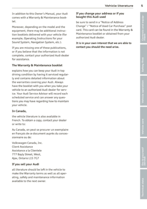 7
7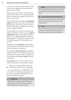 8
8 9
9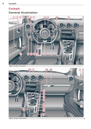 10
10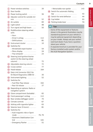 11
11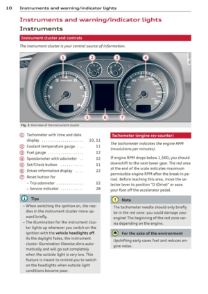 12
12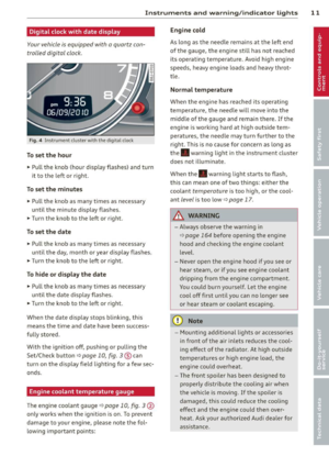 13
13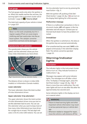 14
14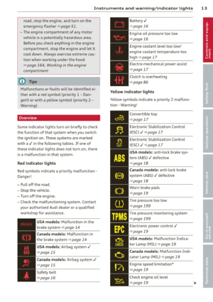 15
15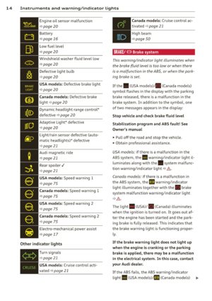 16
16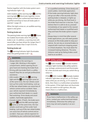 17
17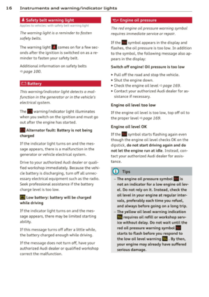 18
18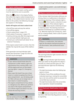 19
19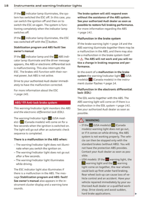 20
20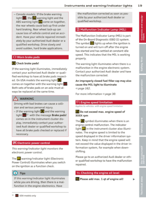 21
21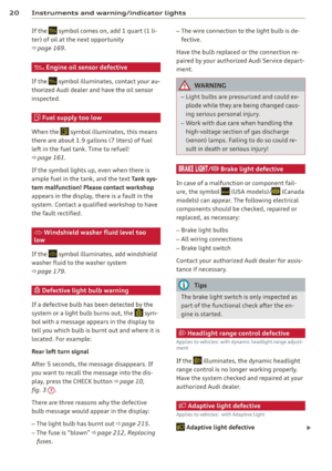 22
22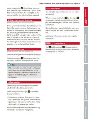 23
23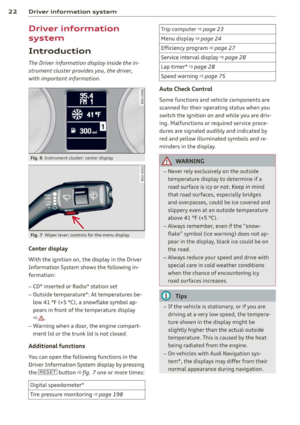 24
24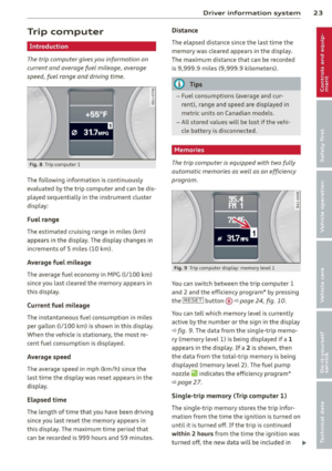 25
25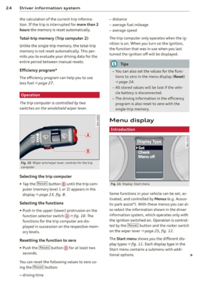 26
26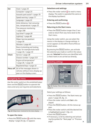 27
27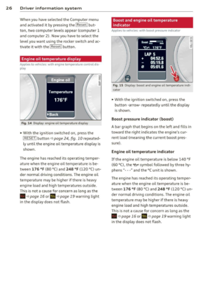 28
28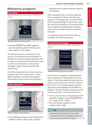 29
29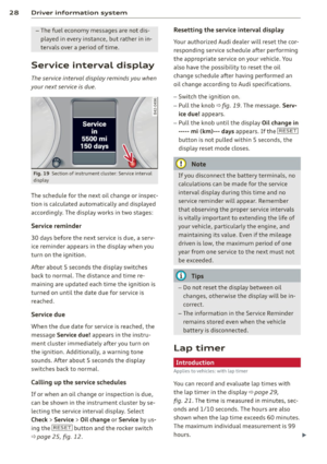 30
30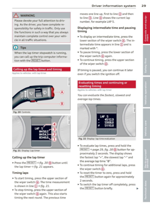 31
31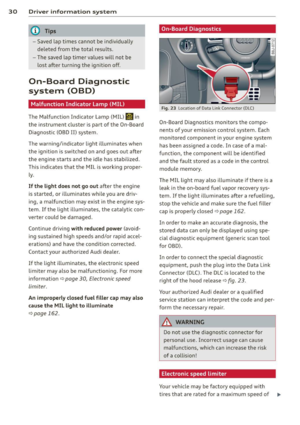 32
32 33
33 34
34 35
35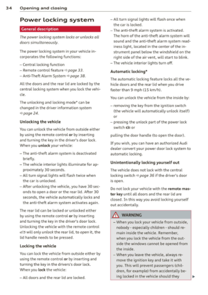 36
36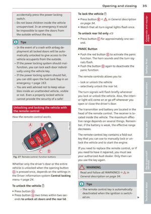 37
37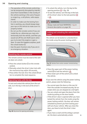 38
38 39
39 40
40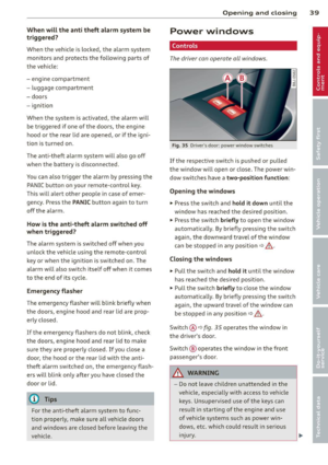 41
41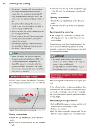 42
42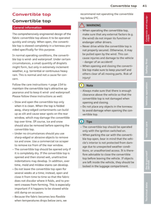 43
43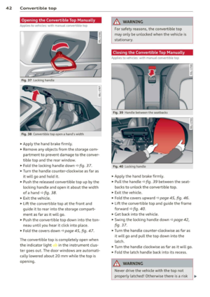 44
44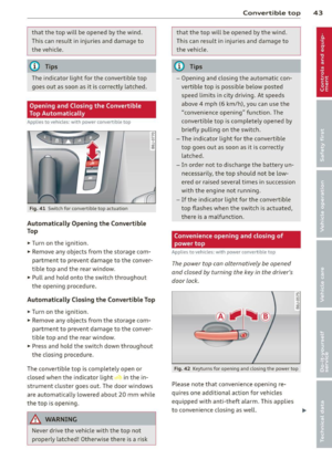 45
45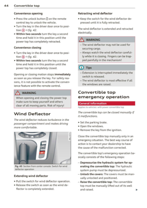 46
46 47
47 48
48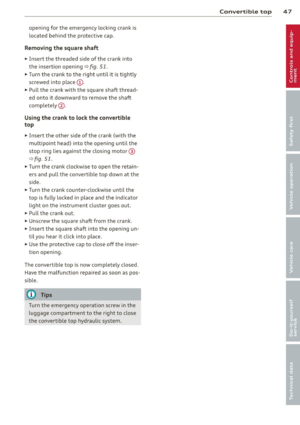 49
49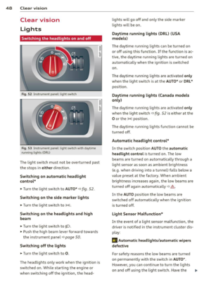 50
50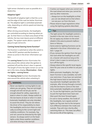 51
51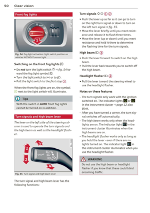 52
52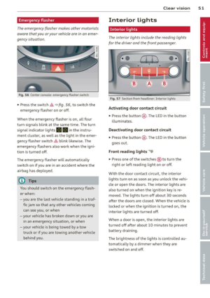 53
53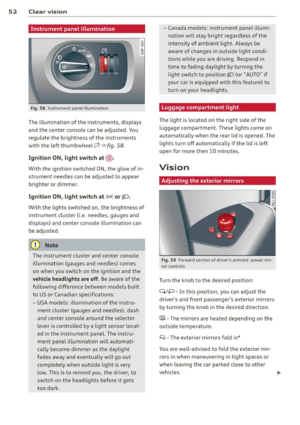 54
54 55
55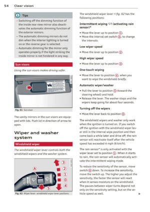 56
56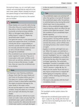 57
57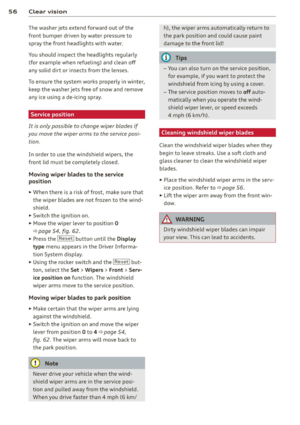 58
58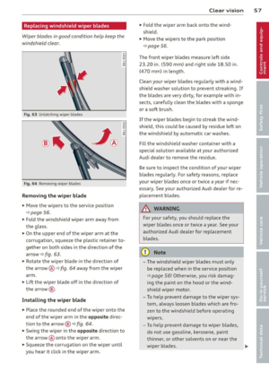 59
59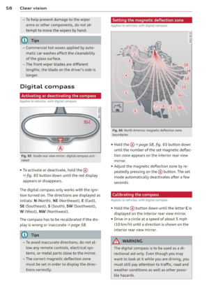 60
60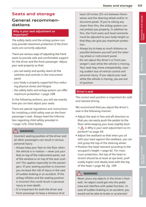 61
61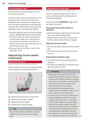 62
62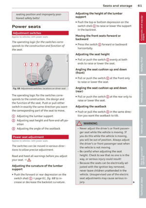 63
63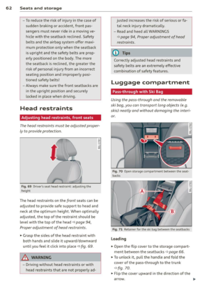 64
64 65
65 66
66 67
67 68
68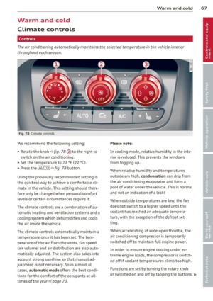 69
69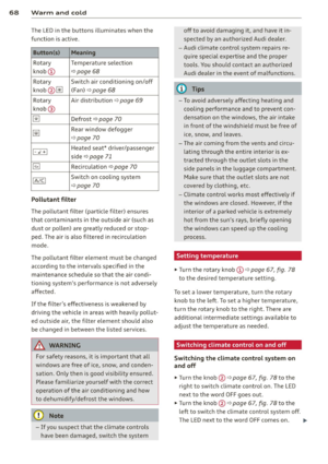 70
70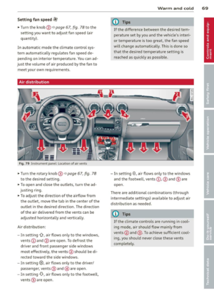 71
71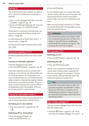 72
72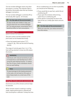 73
73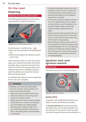 74
74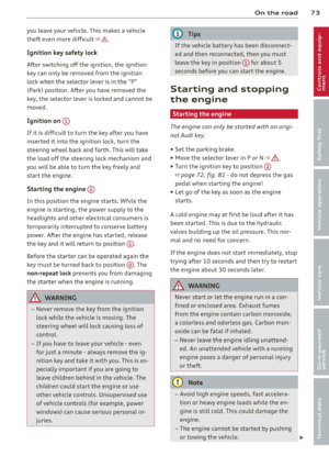 75
75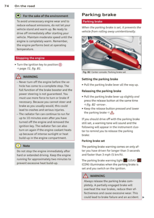 76
76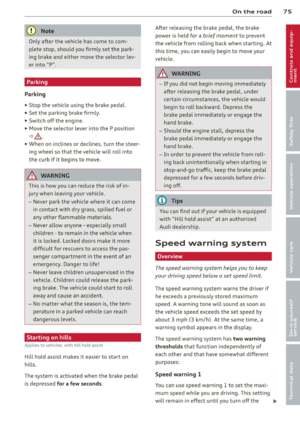 77
77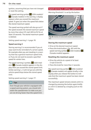 78
78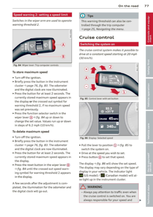 79
79 80
80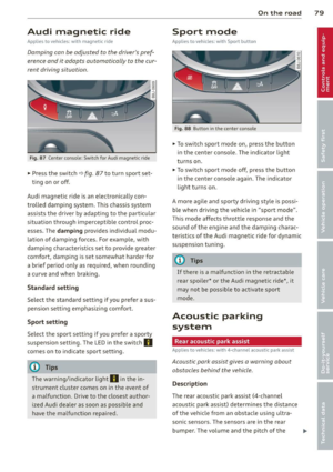 81
81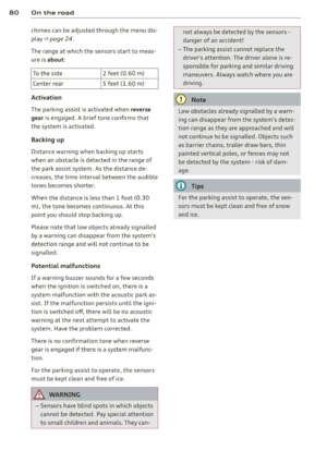 82
82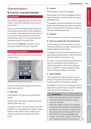 83
83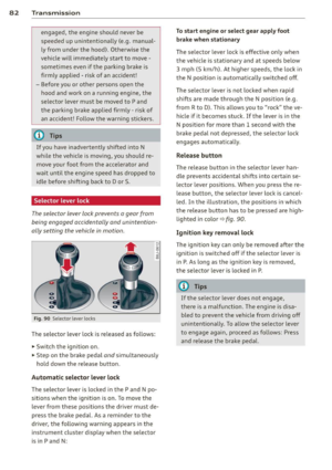 84
84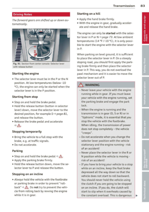 85
85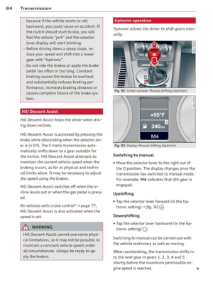 86
86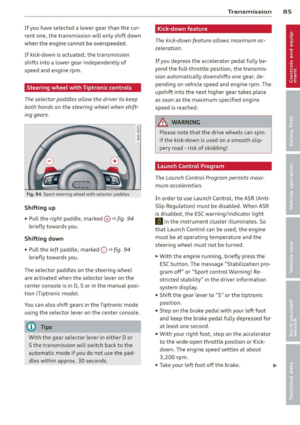 87
87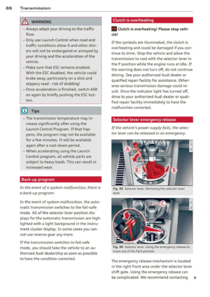 88
88 89
89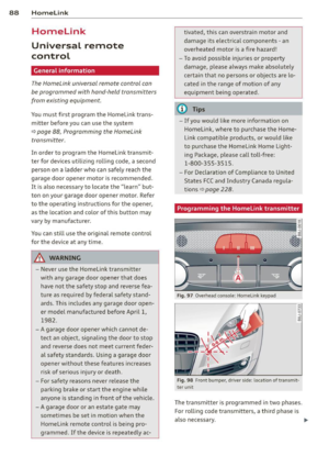 90
90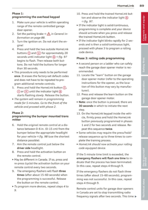 91
91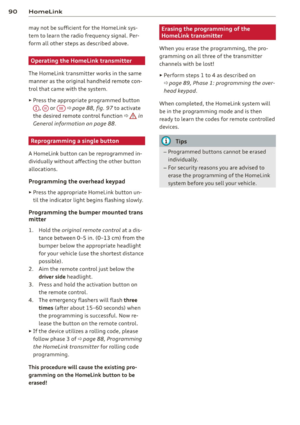 92
92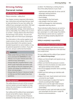 93
93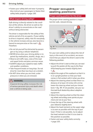 94
94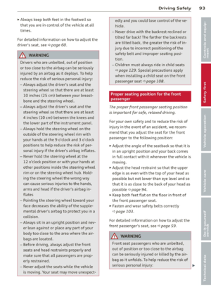 95
95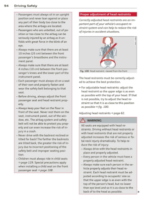 96
96 97
97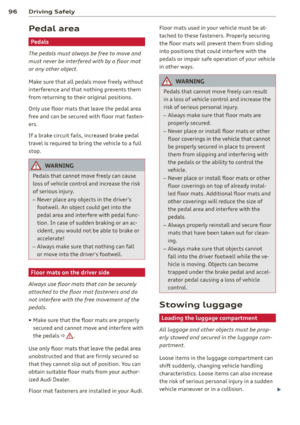 98
98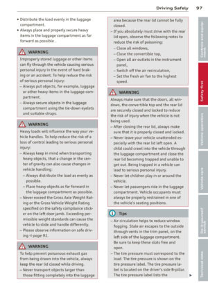 99
99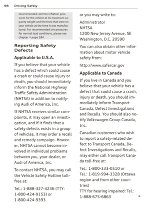 100
100 101
101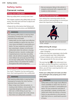 102
102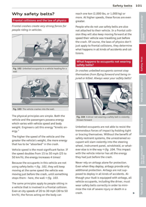 103
103 104
104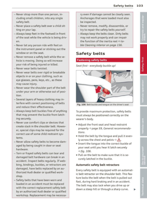 105
105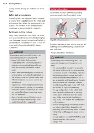 106
106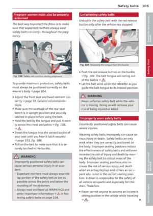 107
107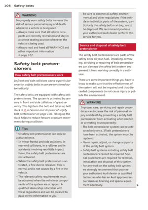 108
108 109
109 110
110 111
111 112
112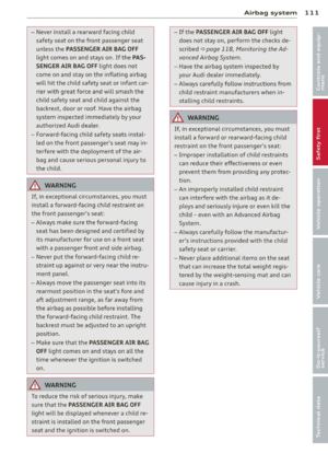 113
113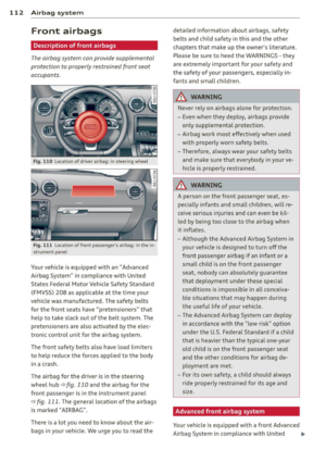 114
114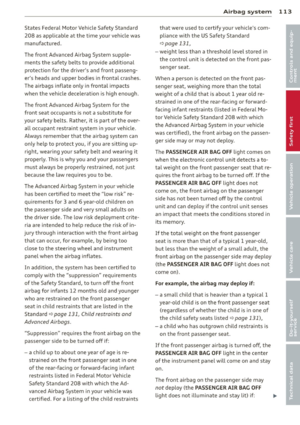 115
115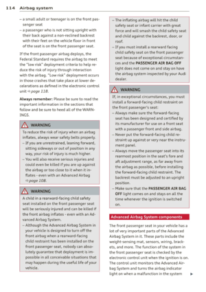 116
116 117
117 118
118 119
119 120
120 121
121 122
122 123
123 124
124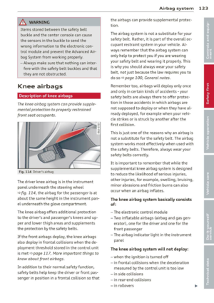 125
125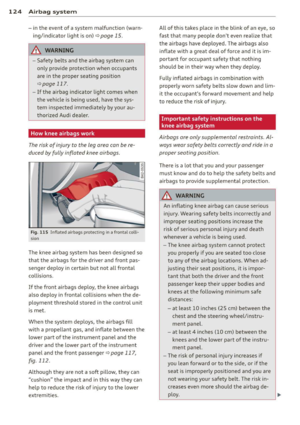 126
126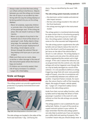 127
127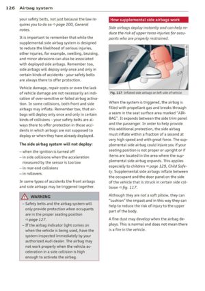 128
128 129
129 130
130 131
131 132
132 133
133 134
134 135
135 136
136 137
137 138
138 139
139 140
140 141
141 142
142 143
143 144
144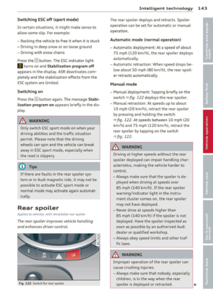 145
145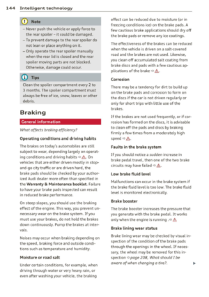 146
146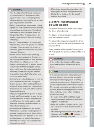 147
147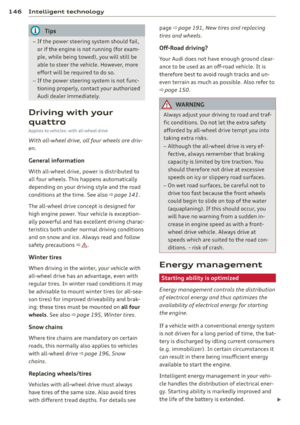 148
148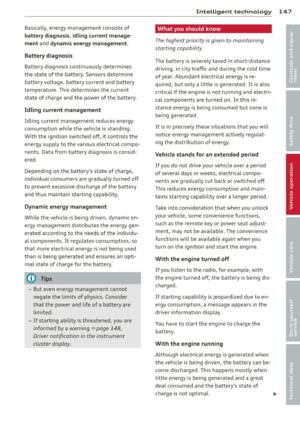 149
149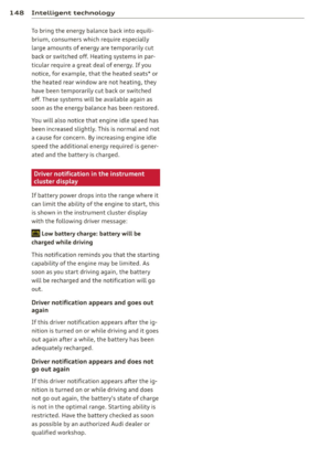 150
150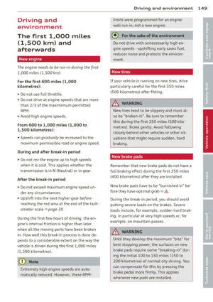 151
151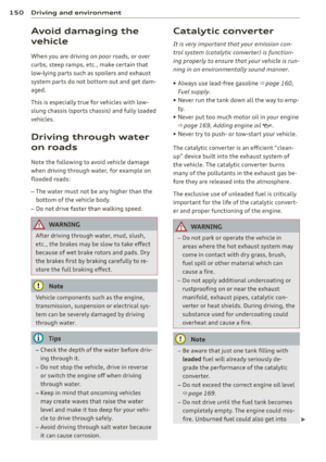 152
152 153
153 154
154 155
155 156
156 157
157 158
158 159
159 160
160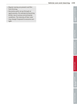 161
161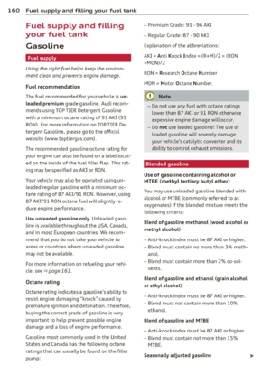 162
162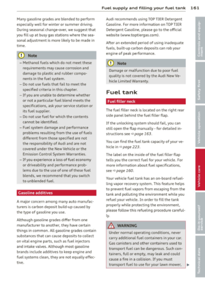 163
163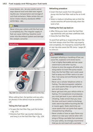 164
164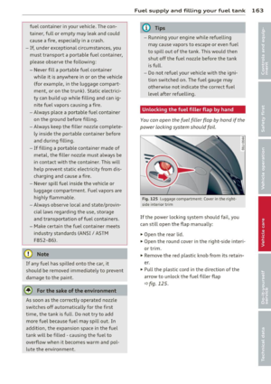 165
165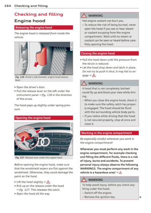 166
166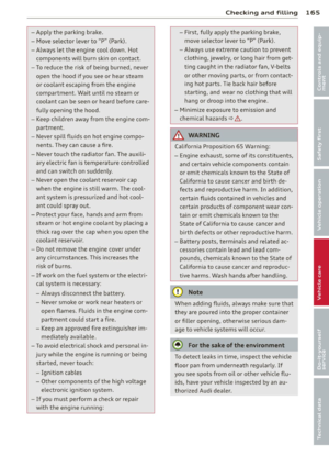 167
167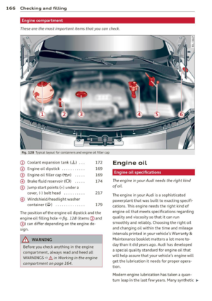 168
168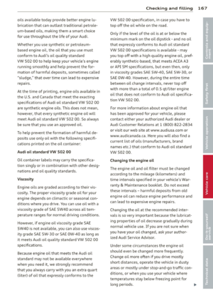 169
169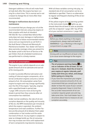 170
170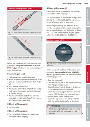 171
171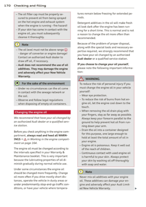 172
172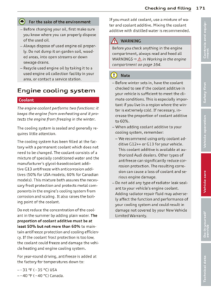 173
173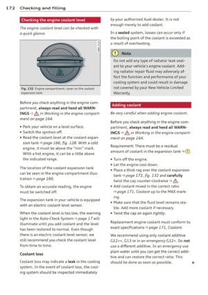 174
174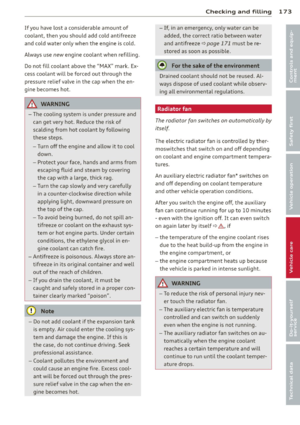 175
175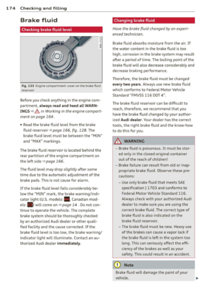 176
176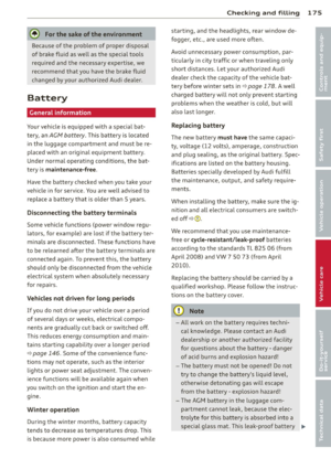 177
177 178
178 179
179 180
180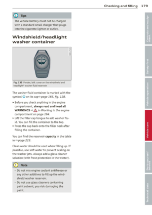 181
181 182
182 183
183 184
184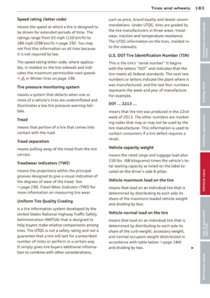 185
185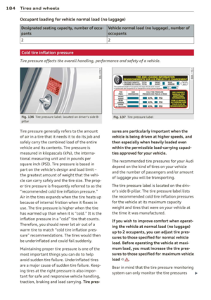 186
186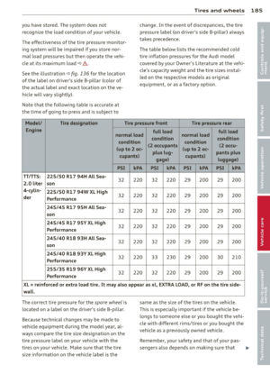 187
187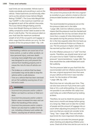 188
188 189
189 190
190 191
191 192
192 193
193 194
194 195
195 196
196 197
197 198
198 199
199 200
200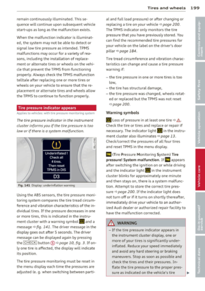 201
201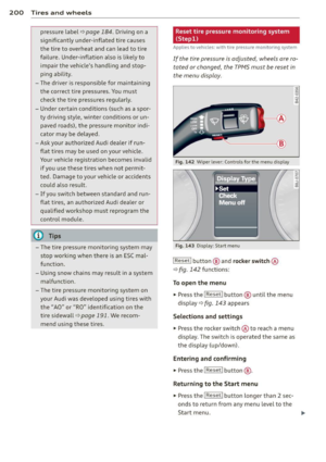 202
202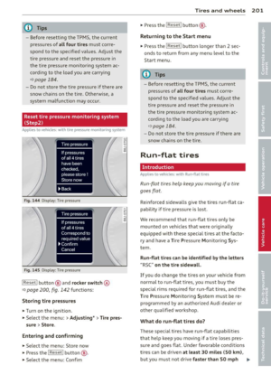 203
203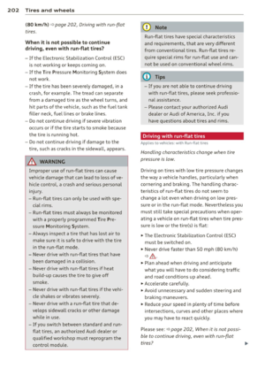 204
204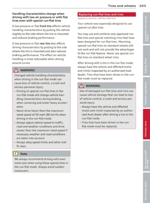 205
205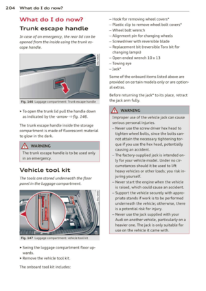 206
206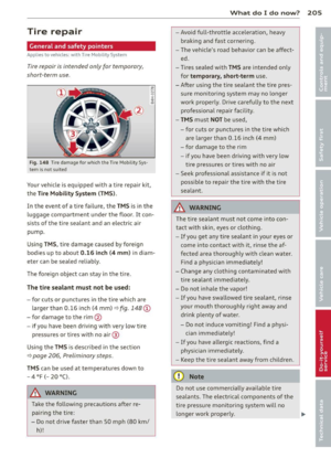 207
207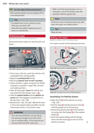 208
208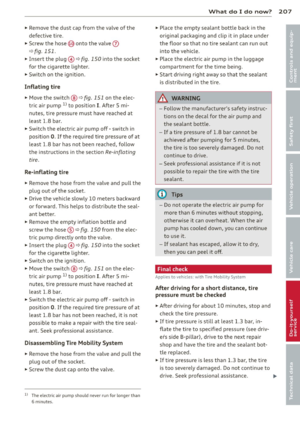 209
209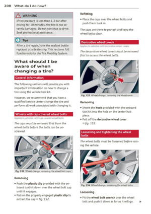 210
210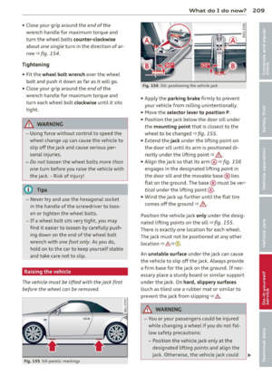 211
211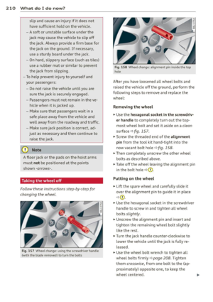 212
212 213
213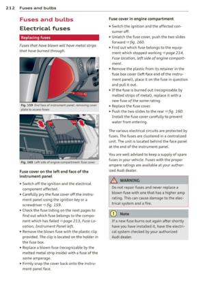 214
214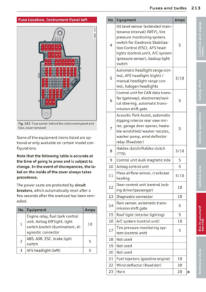 215
215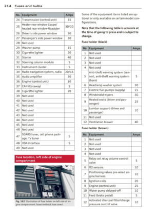 216
216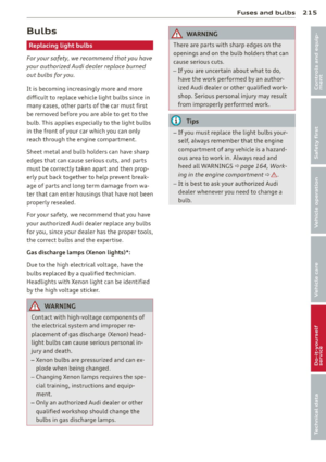 217
217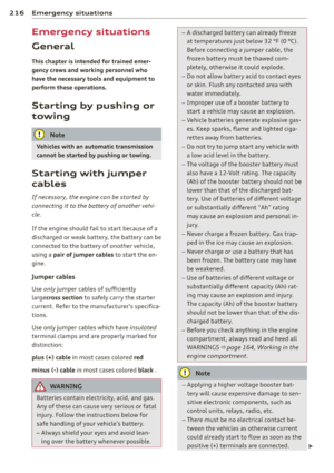 218
218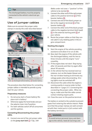 219
219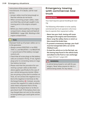 220
220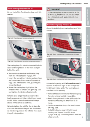 221
221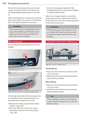 222
222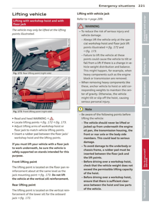 223
223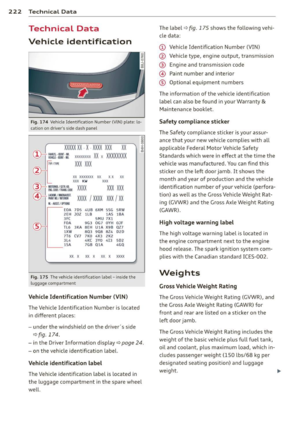 224
224 225
225 226
226 227
227 228
228 229
229 230
230 231
231 232
232 233
233 234
234 235
235 236
236 237
237 238
238 239
239 240
240 241
241 242
242 243
243