Page 209 of 244
 onto the va lve 0
¢ fig . 151.
~ Inser t the plug @¢ fig. 150 into the socket
for the cigarette l")
~ Remove the dust cap from the valve of the
defective tire.
~ Screw the hose@) onto the va lve 0
¢ fig . 151.
~ Inser t the plug @¢ fig. 150 into the socket
for the cigarette lighter.
~ Switch on the ignition.
Inflating t ire
~ Move the switch@¢ fig. 151 on the e lec
tric a ir pump
l ) to posit ion I. After 5 mi
nutes, t ire pressure must have reached at
least 1.8 bar .
~ Switch the electric a ir pump off -switch in
pos ition
0 . If the requ ired tire pressure of at
least 1.8 bar has not been reached, follow
the i nstructions in the sec tion
Re-inflating
tire.
Re -inflating tire
~ Remove the hose from the valve and pull the
plug out of the socket.
~ Drive the vehicle slow ly 10 mete rs bac kward
or forward. This helps to dist ribu te t he sea l
ant better .
~ Remove the empty inflation bott le and
screw the hose®¢
fig. 150 from the elec
tric pump directly onto the valve.
~ I nsert the plug@¢ fig. 150 into the socket
for the ciga rette lighter.
~ Switch on the ignition .
~ Move the switch @¢ fig. 151 on the elec
t ric a ir pump
ll to pos it io n I. After 5 mi
nutes, t ire pressure mus t have reached at
least 1.8 b ar.
~ Switch the electric a ir pump off -switch in
position
0 . If the required tire pressure of at
l east 1.8 bar has not been reached, it is not
poss ib le to make a repa ir with the tire seal
ant. Seek professional ass istance.
Disas sembling Tire Mobility System
~ Remove the hose from the valve and p ull the
plug out of the soc ket .
~ Screw the d ust cap onto the va lve.
l ) The e lectr ic a ir pu m p sho uld never r un for lo ng er than
6 m in utes.
What do I do now? 207
~ Place the empty sea lant bott le back in the
original packaging and clip it in place under
the floor so that no tire sea lant can run out
into the veh icle.
~ Place the electric air pump in the luggage
compartment for the t ime being .
~ Start driv ing right away so that the sealant
is dist ributed in the tire.
.&_ WARNING
- Follow the manufacturer 's safe ty inst ru c
tions on the de cal for the ai r pump and
the sealan t bottle .
- If a tire pressure of 1.8 bar cannot be
achieved after pumping for 5 minutes,
the ti re is too severe ly damaged. Do not
continue to drive .
- Seek pro fessional assistance if it is not
possible to repa ir the tire with the t ire
sealant.
(D Tips
- Do not opera te the elec tric air pump fo r
more than 6 minutes without stopping,
otherwise it can overheat . When the ai r
pump has coo led down, you can continue
to use it.
- If sea lant has escaped, allow it to dry,
then yo u can peel it off.
Final check
App lies to vehicles : wi th Tire Mobility Sys tem
After d riv ing for a short d istance , tir e
pressure must be checked
~ After driving for about 10 mi nutes, stop and
check the tire pressure .
~ If tire pressu re is st ill at least 1.3 bar, in
flate the tire to specified press ure (see dr iv
er's side B-pillar), drive to the next repa ir
shop and have the tire and the sealant bot
tle replaced.
~ If tire pressu re is less than 1.3 bar, the t ire
is too severely damaged. Do not continue to
drive . Seek professional assistance. ..,.
•
•
Page 210 of 244

208 What do I do now ?
A WARNING
If tire pressure is less than 1.3 bar after
driving for 10 m inutes, the tire is too se
verely damaged . Do not continue to d rive .
Seek professional assistance .
@ Tips
After a tire repair, have the sealant bo ttle
replaced at a dealersh ip. This restores full
functionality to t he Tire Mob ility System .
What should I be
aware of when
changing a tire?
General information
The fo llow ing se ctions will prov ide yo u with
importa nt information o n how to change a
tire using the vehicle tool kit .
H oweve r, we recomme nd that you have a
q uali fied servi ce center change t he tire and
perform all work associated with changi ng it.
Wheels with cap-covered wheel bolts
Applies to vehicles: with cap-covered wheel bolts
The caps must be removed first from the
wheel bolts before the bolt s can be un
screwed .
Fig. 152 W hee l chan ge: remo ving th e whee l b o lt c aps
R em oving
.. Push the plastic cl ip provided w it h the on
bo ard tool k it down over the wheel bolt cap
until i t engages .
.,. Pull on the properly engaged
plastic clip to
extract the cap
r:> fig . 152 .
Refitting
.,. Place the caps over the whee l bolts and
push them back in.
T he caps are the re to protect and keep the
whee l bolts clean .
Decorative wheel covers
Applies to vehicles: with decorative wheel covers
The d ecorative wheel covers must be remov ed
first to acc ess the wheel bolts.
Fi g. 1 53 Wheel c hang e: re moving t he wh eel c over
Removing
.. Insert the hook provided with the o n board
too l kit into the hole on the center hub
piece .
.. Pull off the
decor ative wheel cover
r:>fig.153 .
Loosening and tightening the wheel
bolts
T he wheel bolts mus t be loosened before rais
ing the vehicle .
Fig . 1 54 Whee l cha nge: loose ning t he whee l bol ts
Loosening
., Fit t he whe el bolt wren ch over the whee l
bolt an d pus h it down as far a s it will go .
Page 211 of 244

.. Close your grip around the end of the
wrench handle for maximum torque and
turn the wheel bolts
c ounter-clockwis e
about one single turn in the direct ion of ar
row
r:> fig . 154.
Tightening
.. Fit the wheel bol t wrench over the wheel
bolt and push it down as far as it will go .
.. Close your grip around the
end of the
wrenc h handle for maximum torque and
turn each wheel bolt
cl ock wis e unt il it sits
t ight .
A WARNING
-Us ing fo rce without control to speed the
wheel change up can cause the veh icle to
slip off the jack and ca use se rious pe r
sonal in juries.
-Do not loosen the wheel bolts more than
one turn
before you ra ise the veh icle with
the jack. -Risk of inj ury!
(1) Tips
- N ever t ry and use the hexagona l socket
i n the handle of the screwdriver to loos
en or tighte n the wheel bolts .
- If a whee l bolt sits very t ight, you may
find i t easie r to loosen by carefully p ush
i ng down on the end of the whee l bolt
wrench with
one foot only . As you do,
ho ld on to the car to keep yourse lf stable
and ta ke care not to slip .
Raising the vehicle
The vehicle must be lifted with the jack first
before the wheel can be removed .
..
Fig. 155 Sill p ane ls: m arkin gs
What do I do now ? 209
Fig. 1 56 Sill : pos itio ning the ve hicle jac k
.. App ly the pa rkin g brake firmly to prevent
your veh icle from rolling unintentionally .
.. Move the
se lect or lever to p osition P .
.. Posit io n the jack be low the door sill unde r
t he
m ounting point tha t is closest to the
wheel to be changed
r=> fig. 155 .
.. Extend the jack under the lifting point on
the door s ill until its arm is positioned di
rectly under the lifting point
c> ,& .
.. Align the jack so that its arm@¢ fig. 156
engages in the designated lift ing point in
the door s ill and the movable base ® lies
flat on the ground . The base @ must be
ver
tical
under the lifting point @ .
.. Wi nd the jack up fu rther u ntil t he f lat t ire
comes off the ground
c> ,& .
Position t he vehicle jack only under the desig
na ted lifting points on the s ill
r:>fig . 155.
T he re is exactly one locat io n for eac h wheel.
T he jack must not be positioned at any other
location ¢
,&¢(D .
An unstable surfa ce unde r the jack ca n cause
the ve hicl e to slip off the jack. Always provide
a firm base for the jack on the gro und . If nec
essary place a sturdy board or s im ilar support
u nder the jack. On
hard , slippery surf aces
(such as tiles) use a rubber mat or similar to
prevent the jack from slipping ¢
.&.
A WARNING
-You or your passengers cou ld be in jured
while changing a wheel if you do not fo l
low safety precautions:
- Position the veh icle jack on ly at the
designated lifting poi nts and align the
j ack. Otherwise, the vehicle jack co uld
Page 212 of 244

210 What do I do now?
slip and cause an injury if it does not
have sufficient hold on the vehicle.
- A soft or unstable surface under the
jack may cause the vehicle to slip off
the jack. Always provide a firm base for
the jack on the ground . If necessary,
use a sturdy board under the jack.
- On hard, slippery surface (such as tiles)
use a rubber mat or similar to prevent
the jack from slipp ing .
- To help prevent injury to yourself and
your passengers:
- Do not raise the vehicle unti l yo u are
sure the jack is securely engaged.
- Passengers must not remain in the ve
hicle when it is jacked up.
- Make sure that passengers wait in a
safe p lace away from the vehicle and
well away from the roadway and traffic.
- Make sure jack position is correct, ad
just as necessa ry and then continue to
ra ise the jack .
(D Note
A floor jack or the pads on the hoist arms
must
not be posit ioned at the points
shown
-arrows- .
Taking the wheel off
Follow these instructions step-by-step for
changing the wheel.
Fig. 157 Wheel ch an ge: us ing the sc rewdrive r hand le
(w ith the b lade removed) to turn the bolts
Fig. 158 Whee l change : alignmen t pin inside the top
hol e
After you have loosened all wheel bolts and
raised the vehicle off the ground, perform the
following steps to remove and replace the
wheel:
Removing the wheel
.,. Use the hexagonal socket in the screwdriv
er handle
to completely turn out the top
most whee l bolt and set it aside on a
clean
surface c;, fig. 15 7.
.,. Screw the threaded end of the
alignment
pin from the tool kit hand-tight into the
now vacant bolt hole <=>
fig. 158 .
.,. Then completely unscrew the other wheel
bolts as described above.
.,. Take off the whee l leaving the alignment pin
in the bolt hole
c;,(D .
Putting on the wheel
.,. Lift the spare wheel and carefully s lide it
over the alignment p in to guide it in place
c;,(D .
.,. Use the hexagonal socket in the screwdriver
handle to screw in and tighten all whee l
bolts
slightly .
.,. Unscrew the alignment p in and insert and
tighten the remaining wheel bolt slightly like the rest .
.,. Turn the jack handle counter-clockwise to
lower the vehicle until the jack is fully re
leased .
.,. Use the wheel bo lt wrench to tighten all
wheel bolts firmly ,=:,
page 208 . Tighten
t hem
crosswise, from one bolt to the ( ap
proximately) opposite one, to keep the
wheel centered.
Page 213 of 244

(D Note
When removing or installing the wheel,
the rim could hit the bra ke rotor and dam
age the rotor . Wor k carefully and have a
second person help you.
N ever use the hexa gonal s ocket in the ha n
d le of the screwdriver to loosen or t ighten
the wheel bolts.
- Pull the reversib le blade from the screw
drive r before yo u use the hexagonal
socket in t he handle to t urn the whee l
bo lts .
- When mounting tires with
unid irectional
tread design
make s ure the tread pat
te rn is poi nte d the r ight way
¢pag e 211.
- The wheel bolts should be clea n and easy
to tu rn . Ch eck for dirt and corros ion on
the mat ing su rfaces of both the whee l
a nd th e hu b. Remove a ll dir t fro m these
s ur fa ces before remo unting the wheel.
Notes on wheel change
Pl ease rea d the information ¢ page 191, New
tires and replacing tires and wheels,
i f you are
going to use a spare t ire which is different
from the tires on your ve hicle.
Afte r you change a tire:
- Check the tire pressure on the spare imme
diately after mounting .
- Have the wheel bolt tightening torque
che cked with a torque wrench as soon as
possible by your authorized Audi dealer or
a qualified service station.
- With steel and alloy wheel rims, the wheel
bolts are correctly tightened at a torque of
90 ft lb (120 Nm) .
- If you notice while changing a tire that the
wheel bolt s are co rroded and diffi cult to
turn , then they should be replaced before
you check the t ightening torque.
What do I do now? 211
- Replace the flat tire with a new one and
have it installed on your vehicle as soon as
possible. Remount the wheel cover .
Until then , drive with extra care and at re
duced speeds.
A WARNING
-
- If you are go ing to e quip your ve hicl e
wit h tires o r rims which differ from those
which were factory installed, t hen be
sure to read the information¢
page 191,
New tires and replacing tires and
wheels .
-Always sto re the tools secu rely in lug
gage compartment. Othe rwise, in a n ac
cident o r su dd en maneuv er they cou ld fly
forwa rd, causi ng injury to passe ngers in
the vehicle.
Tires with unidirectional tread design
Tires with unidirectional tr ead design must be
mounted with their tread pattern pointed the
right dire ction.
A u nidirectional tire can be identified by ar
rows on the sidewall,
which point in the direc
tion of t he rota tion. Yo u m ust follow the
s p ecifie d direction of rot ation. This i s nece ssa
r y in order fo r these tires to develop t heir op
timum charac ter istics regard ing grip, road
no ise, wear, and hydrop la ning.
•
•
Page 214 of 244

212 Fuses and bulbs
Fuses and bulbs
Electrical fuses
Replacing fuses
Fuses that have blown will have metal strips
that have burned through .
Fig. 159 End face of instrument panel: rem ov ing cover
p la te to access fuses
Fig. 160 Left side of eng ine compart men t: fuse cove r
Fuse cover on the left end face of the
inst rument pane l
.. Switch off the ignition and the electrical
component affected.
.. Carefully pry the fuse cover off the instru
ment panel using the ignition key or a
screwdriver
c;::> fig. 159 .
.. Check the fuse list ing on the next pages to
find out which fuse belongs to the compo
nent which has failed
o page 213, Fuse Lo
cation, Instrument Panel left .
.. Remove the blown fuse with the plastic clip
provided. The cl ip is located on the holder in
the fuse box .
.. Replace a blown fuse (recognizable by the
melted metal str ip ins ide) with a fuse of the
same amperage .
.. Firmly snap the cover back onto the instru
ment pane l face .
Fuse cover in engine compartment
.. Switch the ignit ion and the affected con
sumer off .
.. Unlatch the fuse cover , push the two slides
forward
c;::> fig. 160.
.. Find out which fuse belongs to the equip
ment which stopped working
c;::> page 214,
Fuse location , le~ side of engine compart
ment .
.. Remove the plastic from its retainer in the
fuse box cover (left face end of the instru
ment panel), place it on the fu se in question
and pull it out .
.. If the fuse is burned out (recognizable by
melted strips of metal), replace it with a
new fuse
of the same rating.
.. Replace the fuse cover .
.. Push the two slides to the rear
o fig. 160.
Install the fuse cover carefully to prevent
water from enter ing .
The various electrical circuits are protected by
fuses. The fuses are clustered in a centralized unit. The unit is located behind the face panel
at the end of the instrument panel.
You are well advised to keep a supply of spare
fuses in your vehicle. Fuses with the proper
ampere ratings are available at your author
ized Audi dealer.
A WARNING -
Do not repa ir fuses and never replace a
blown fuse with one that has a higher amp
rating. This can cause damage to the elec
trica l system and a fire.
(D Note
If a new fuse burns out again after shortly
have you have installed it, have the electri
ca l system checked by your authorized
Audi dealer.
Page 215 of 244

Fuse Location, Instrument Panel left
0
Fig. 161 Fuse carrier behind the instrument panel end
face, cover removed
Some of the eq u i prnent items listed a re op
tional or only available on certain model con
f igurations.
Note that the following table is accurate at
the time of going to press and is subject to
change. In the event of d iscrepancies, the la
bel on the in side of the cover always takes
precedence .
The power seats are protected by circuit
breakers ,
which automatically reset after a
few seconds after the overload has been rem
ed ied.
No. Equipment Amps
Engine relay, fuel tank cont ro l
1
unit, A irbag Off light, light
10 switch (sw itch illumi nation), di-
agnostic connector
2
ABS, ASR, ESC, brake light
5 switch
3 AFS headlight (left) 5
No.
4
5
6
7
8
9
10
11
12
13
14
15
16
17
18
19
20
21 22
23
Fuses and bulbs 213
Equipment Amps
Oil level sensor (extended main-
tenance interval)
(WIV), t ir e
press ure monitoring system,
sw itch for Electron ic Stabiliza-
5 tion Control (ESC), AFS head-
lights (control unit), A/C system
(pressure sensor), backup light
sw itch
Automatic headlight range con- trol, AFS headlight (right) /
5/10
manual headlight range con-
trol, halogen headlights
Control unit for CAN data trans-
fer (gateway), electrornechani-
5 cal steering, automatic trans-
miss ion shift gate
Acoustic Park Assist, automatic
d ip ping interior rear
view rnir-
ror, garage door opener, heata-
5 ble windshield washer nozzles,
washer pump, w ind deflector
relay (Roadster)
H aldex clutch/Ha ldex clutch
5/10 (TTS)
Control un it Audi magnetic ride
5
A irbag contro l unit 5
Mass airflow sensor, crankcase 5/10
heating
Door control unit (central lock -
10 ing driver/passenger)
Diagnostic connector
10
Rain sensor, automatic trans-
5 miss ion sh ift gate
Roof light (interior lighting)
5
A/C system (contro l unit) 10
Tire pressure monitoring sys -
5 tern (control un it)
Not used
Not used
Not used
Fuel injectors (gasoline eng ine)
10
Wind deflector (Roadster) 30
Horn 20
Page 216 of 244

25 Heate
r rear window Coupe /
heated rear window Roadster
26 Driver
s side power window
27 Passengers s ide p")
214 Fuses and bulb s
No. Equipment
24 Transmi ssion (contro l un it)
25 Heate
r rear window Coupe /
heated rear window Roadster
26 Driver'
s side power window
27 Passenger's s ide power window
28 No
t used
29 Washer pump
30 Cigarette lighter
31 Start er
32 Steering column module
33 Instrument clust er
34 Radio navigation system , radio
35 Aud io amplifi er
36 Engine (control un it)
37 CAN (Gat
eway)
38 Ciga
rette lighter
39 Not us ed
40 Not used
4 1 Not u sed
42 Not used
43 No t used
44 Not used
45 No
t used
46 Not used
47 SOARS tuner, cell phone pack-
age,
TV tuner
48 VOA interface
49 Not used
Fuse location, left side of engine
compartment Amps
15
30/ 20
30 30
15
20
40 5
5
20/15
30 10
5
20
5 5
Fi g. 162 Ill ustra tion of fus e ho lde r on l eft side o f en·
gi ne compar tment: fuse s (withou t fuse c over)
Some of the equipment items listed are op
tiona l or only avai lable on c ertain mod el con
figurations.
Note tha t the foll owing table i s ac cur ate at
the time of going to pre ss and is subject to
change .
Fus e holder (bla ck )
No . Equipment Amps
1 Not used
2 Not used
3 Not used
4 No t used
Anti- theft warning system (sen -
5 sor), ant
i-theft warn ing system
5
(horn)
6 Headlamp washer system
30
7 Elec
tric fuel pumps (supp ly)
15
8 W
indshield wipers
30
9 H
eat ed seats (dr iver and pas-
25
senger)
10 L
umbar support (d river and
10
passenger)
11 Not u sed
12 Vent ilation blower 40
Fus e holder (brown )
No. Equipment Amps
1 Not used
2 Not used
3 Not used
4 Not used
5 Relay coil
relay volume cont ro l
5
va lve
6 02
sensors
10
7 P
ositioning valves pre-wired en-
10
gine harness
8 Ignition coi ls 20
9 Eng
in e (cont rol unit)
25
10 Water pump de layed-off 10
1 1 F
e e d (brak e pedal)
5
1 2 Activated charcoal filter/charge
10
p ress ure control va lve
 1
1 2
2 3
3 4
4 5
5 6
6 7
7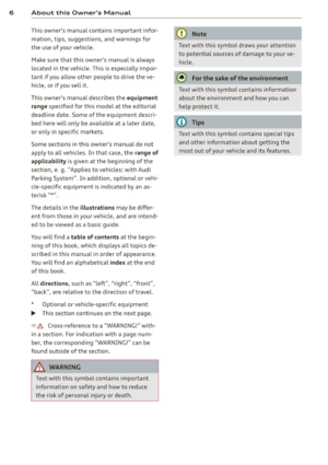 8
8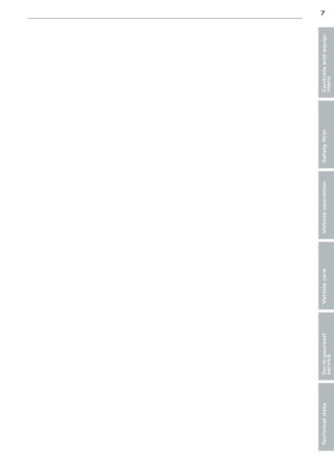 9
9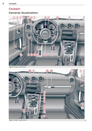 10
10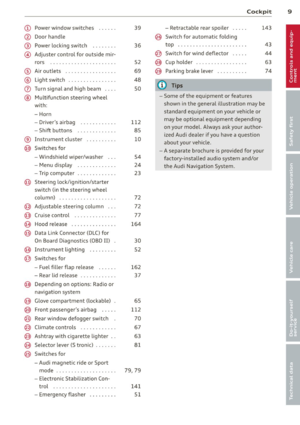 11
11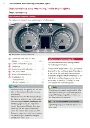 12
12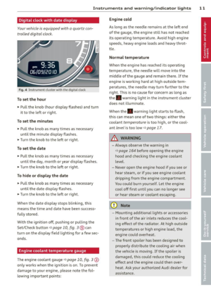 13
13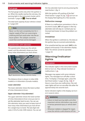 14
14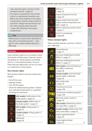 15
15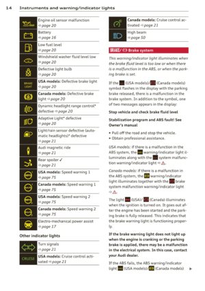 16
16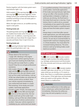 17
17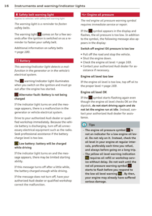 18
18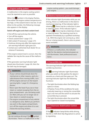 19
19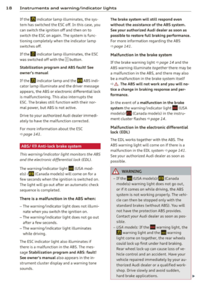 20
20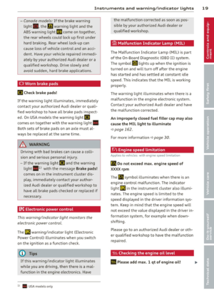 21
21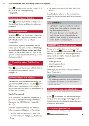 22
22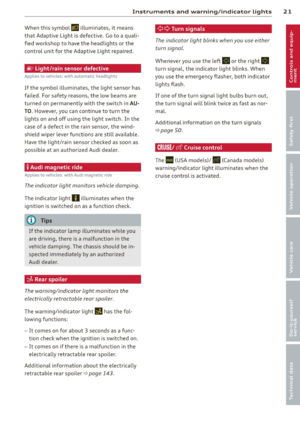 23
23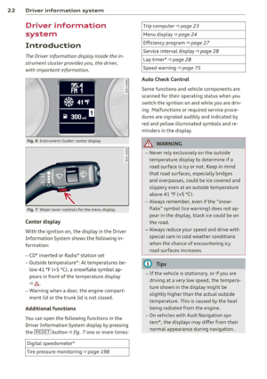 24
24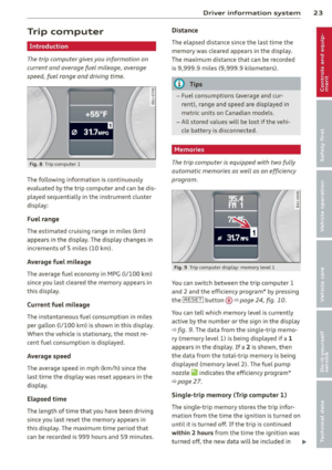 25
25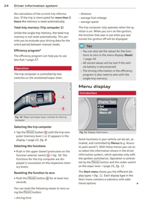 26
26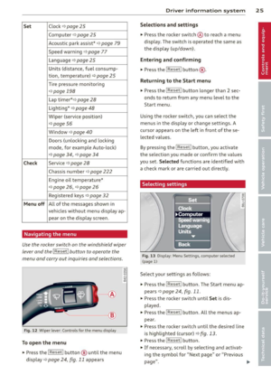 27
27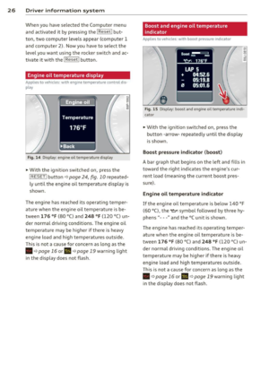 28
28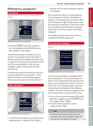 29
29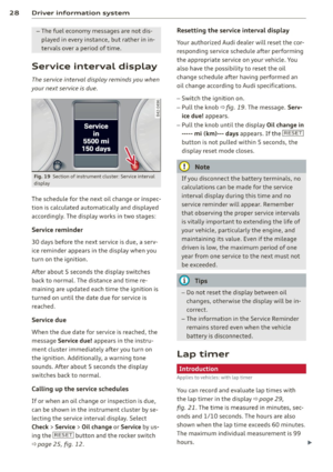 30
30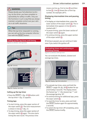 31
31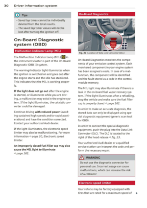 32
32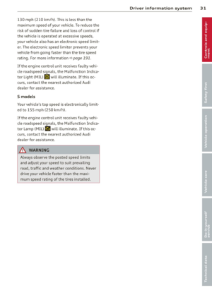 33
33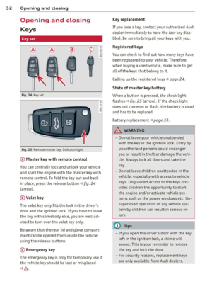 34
34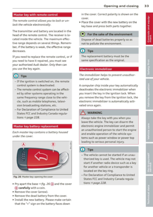 35
35 36
36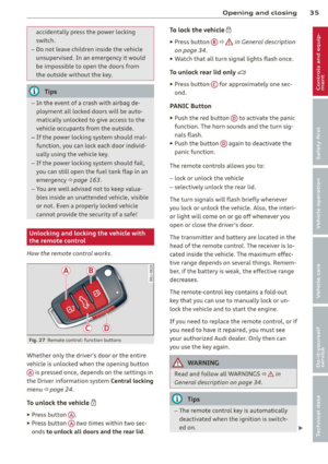 37
37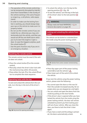 38
38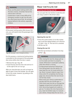 39
39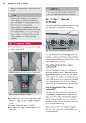 40
40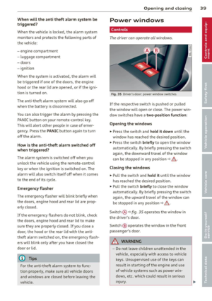 41
41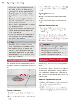 42
42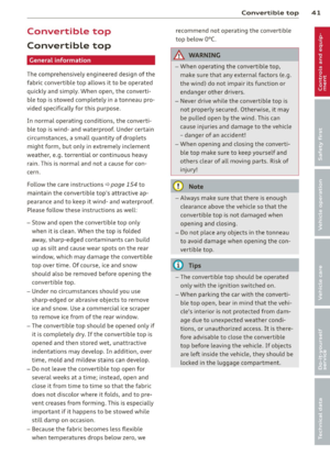 43
43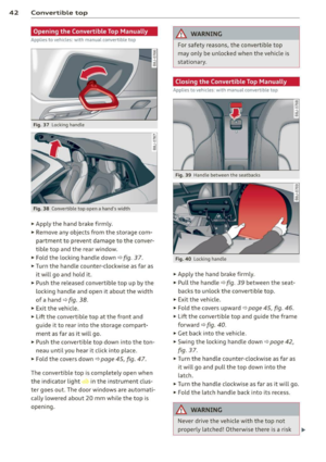 44
44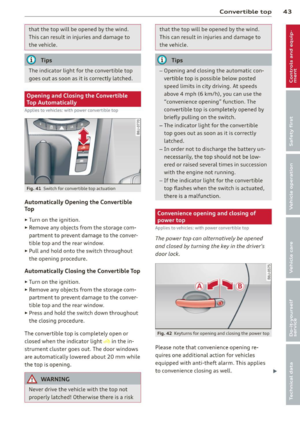 45
45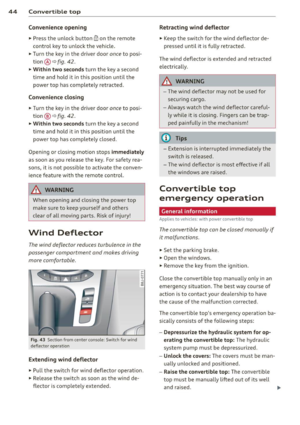 46
46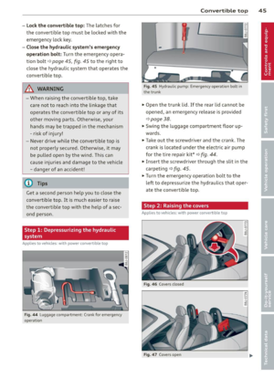 47
47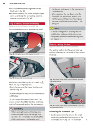 48
48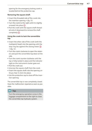 49
49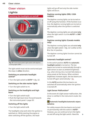 50
50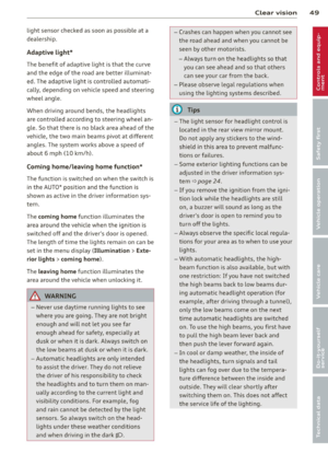 51
51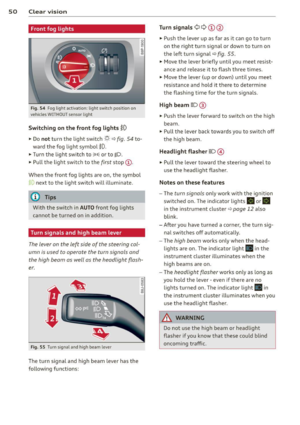 52
52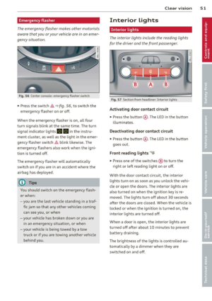 53
53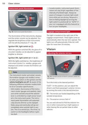 54
54 55
55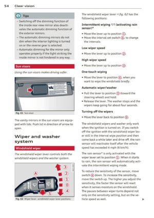 56
56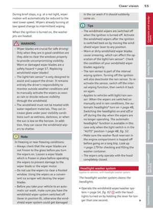 57
57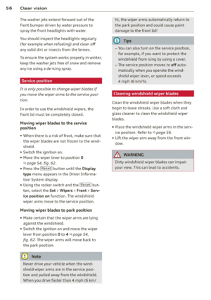 58
58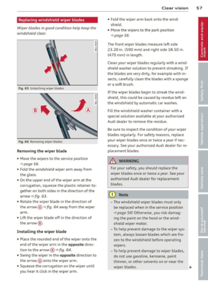 59
59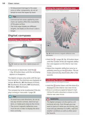 60
60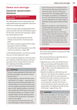 61
61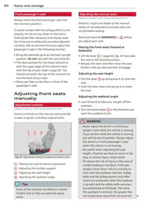 62
62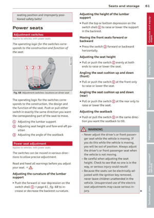 63
63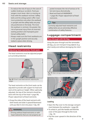 64
64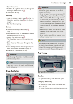 65
65 66
66 67
67 68
68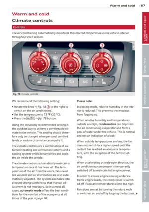 69
69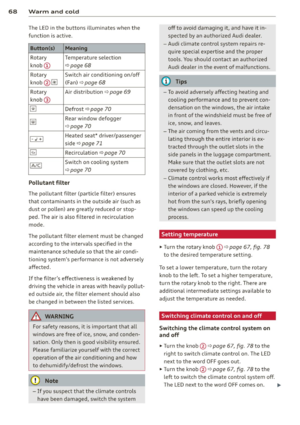 70
70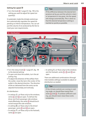 71
71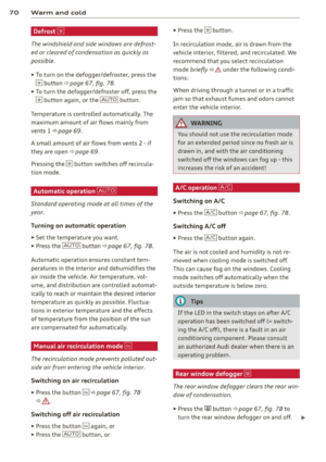 72
72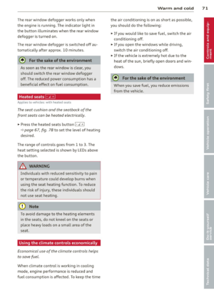 73
73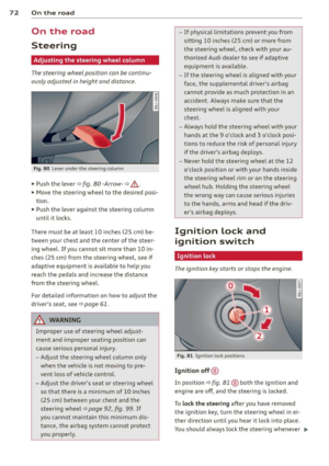 74
74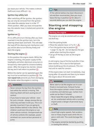 75
75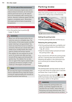 76
76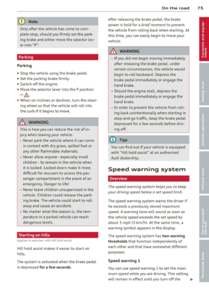 77
77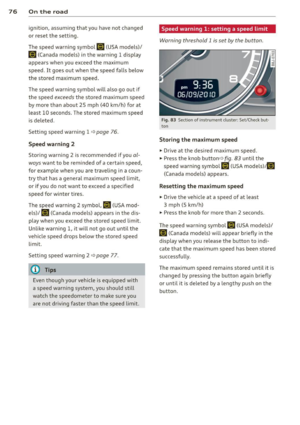 78
78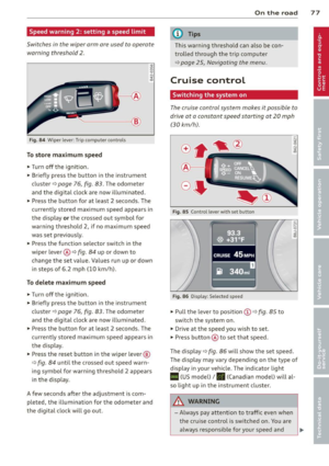 79
79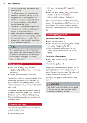 80
80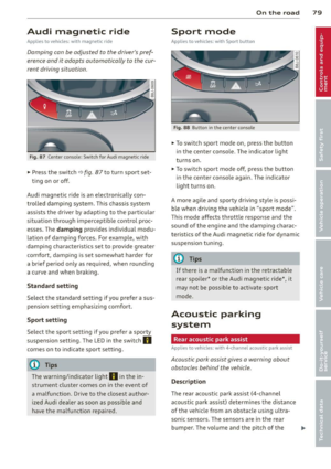 81
81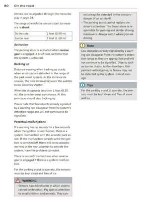 82
82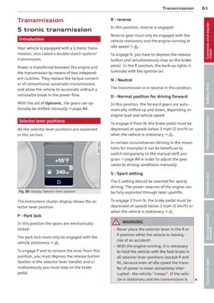 83
83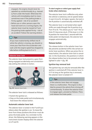 84
84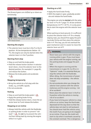 85
85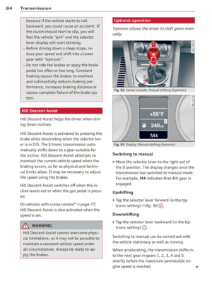 86
86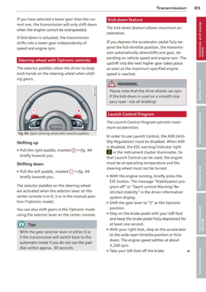 87
87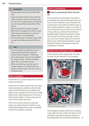 88
88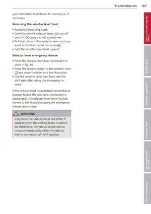 89
89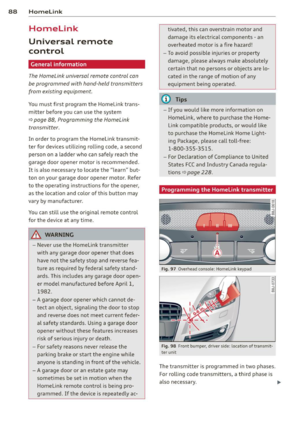 90
90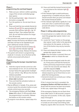 91
91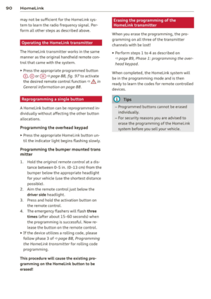 92
92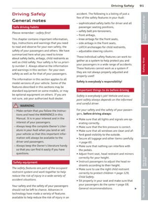 93
93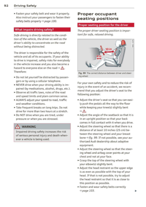 94
94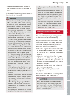 95
95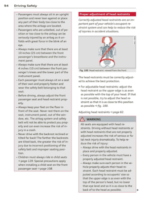 96
96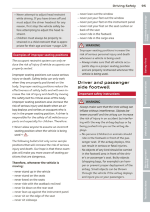 97
97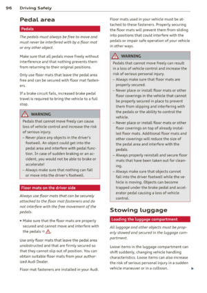 98
98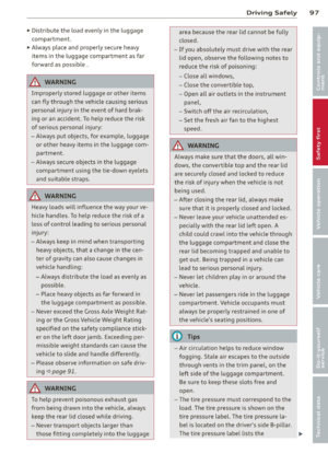 99
99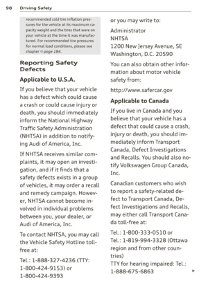 100
100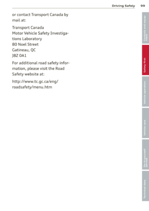 101
101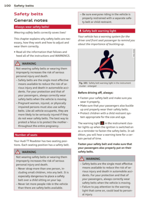 102
102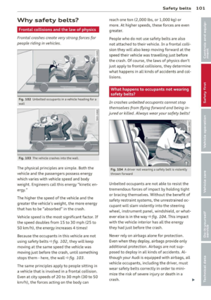 103
103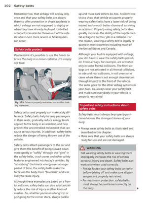 104
104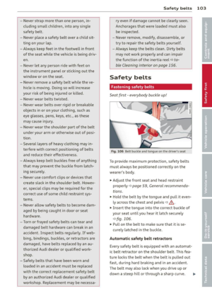 105
105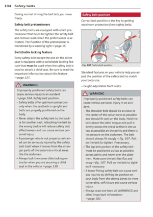 106
106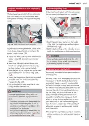 107
107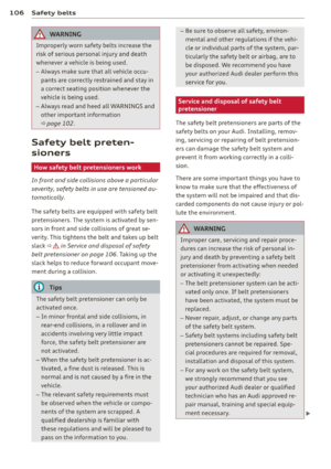 108
108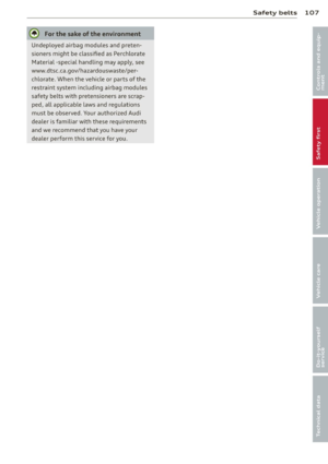 109
109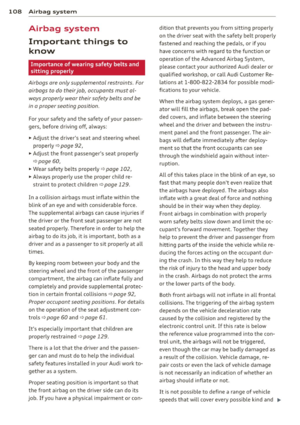 110
110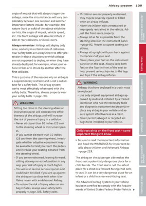 111
111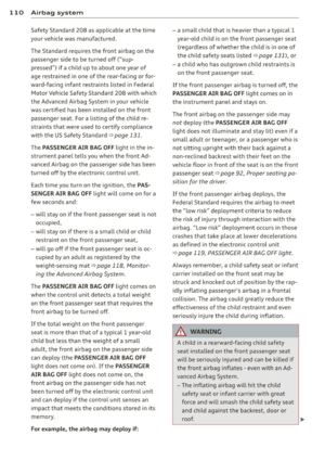 112
112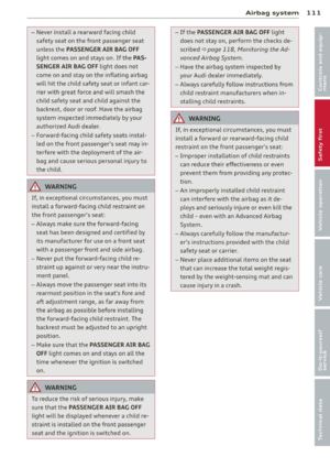 113
113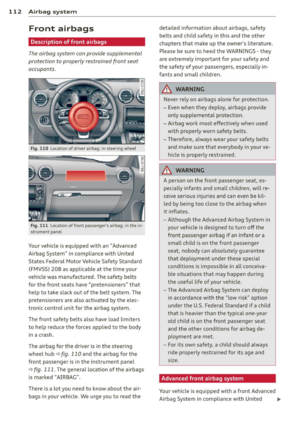 114
114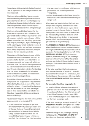 115
115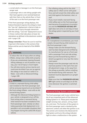 116
116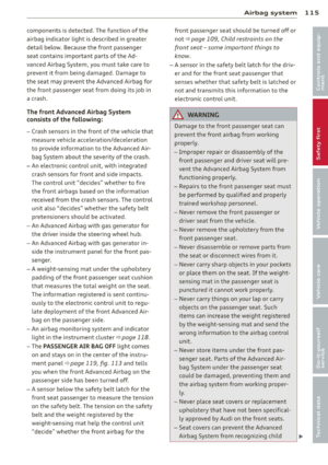 117
117 118
118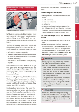 119
119 120
120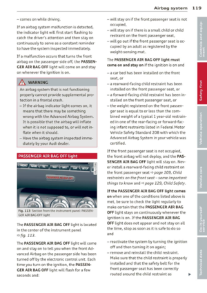 121
121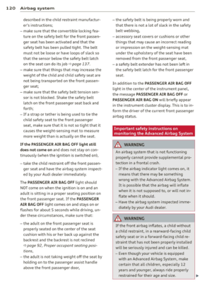 122
122 123
123 124
124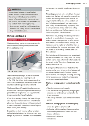 125
125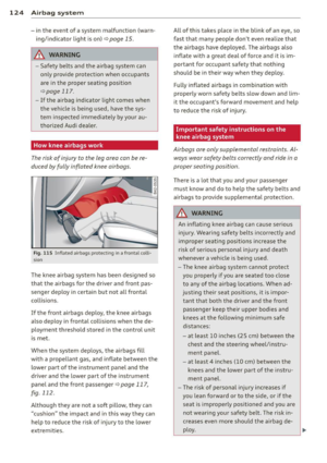 126
126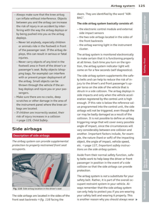 127
127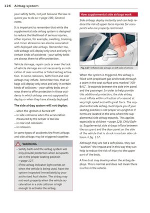 128
128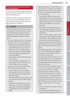 129
129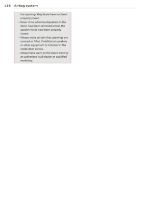 130
130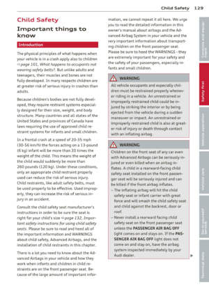 131
131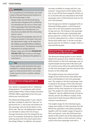 132
132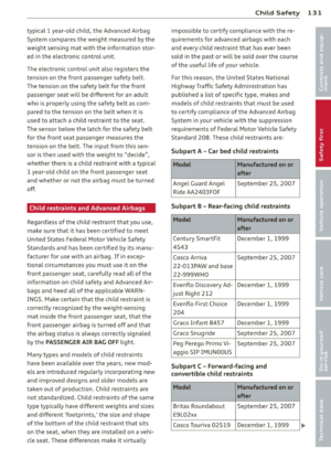 133
133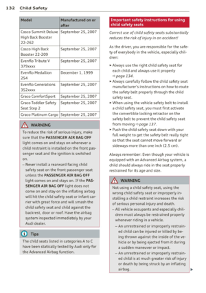 134
134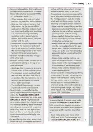 135
135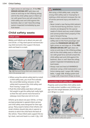 136
136 137
137 138
138 139
139 140
140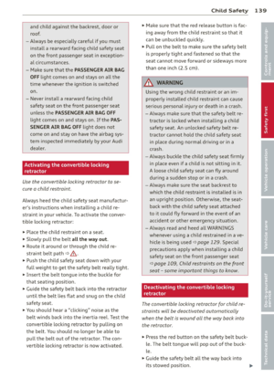 141
141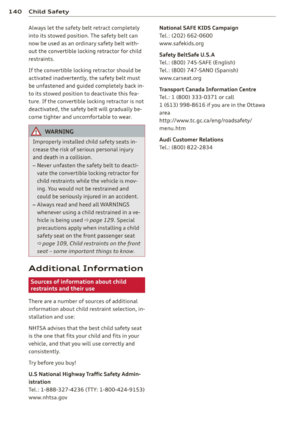 142
142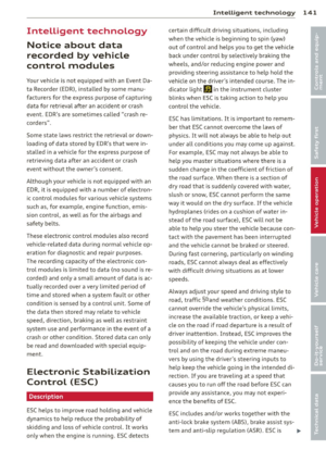 143
143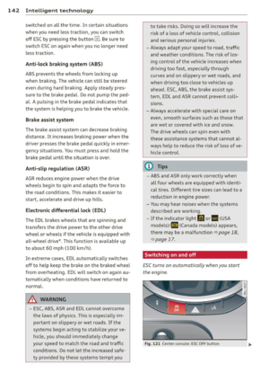 144
144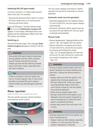 145
145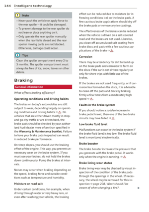 146
146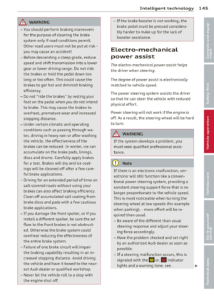 147
147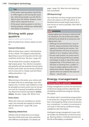 148
148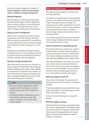 149
149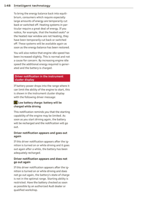 150
150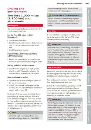 151
151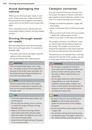 152
152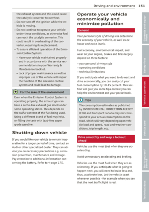 153
153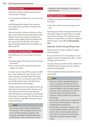 154
154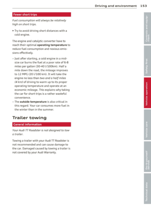 155
155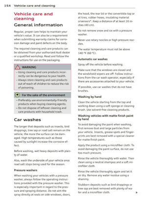 156
156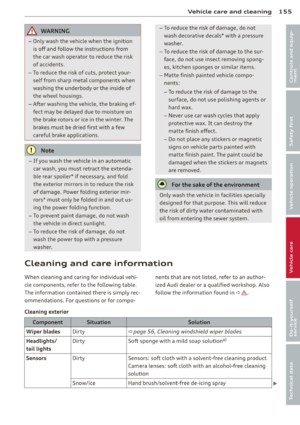 157
157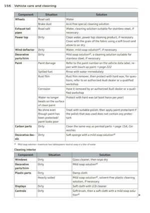 158
158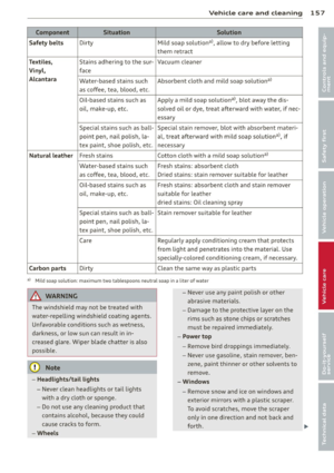 159
159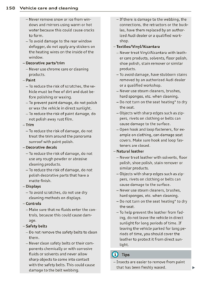 160
160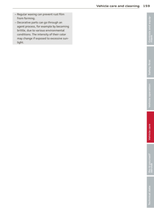 161
161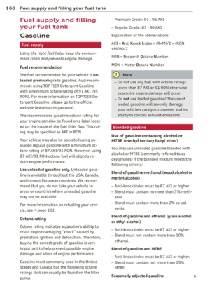 162
162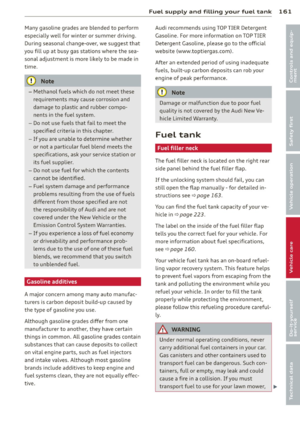 163
163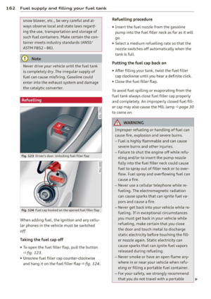 164
164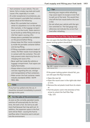 165
165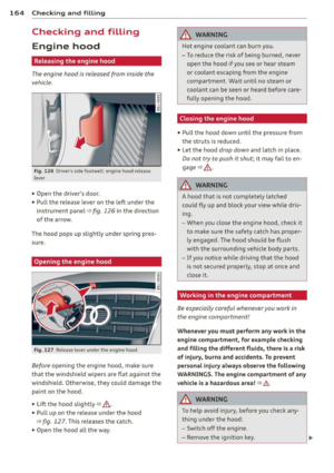 166
166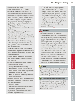 167
167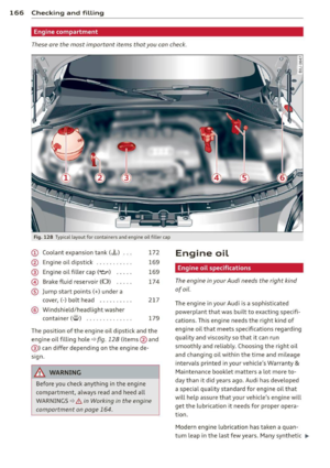 168
168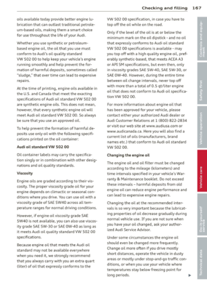 169
169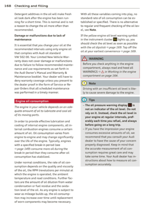 170
170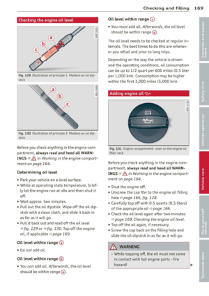 171
171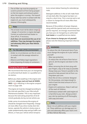 172
172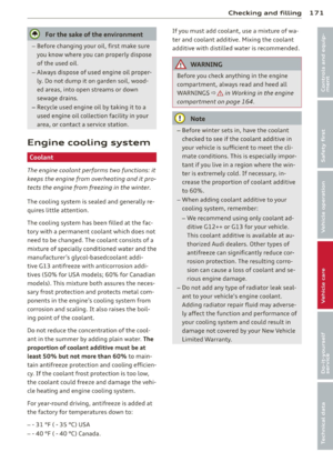 173
173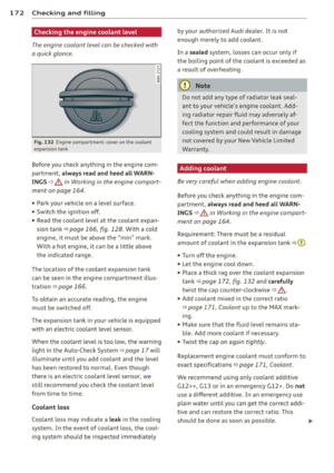 174
174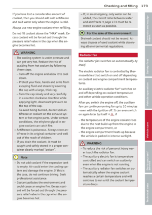 175
175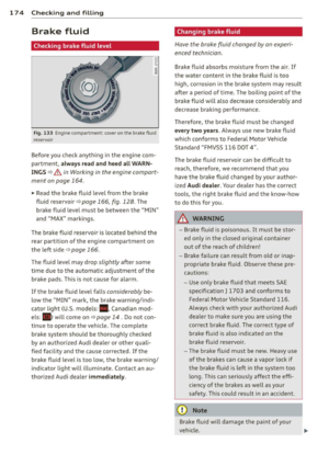 176
176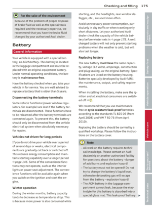 177
177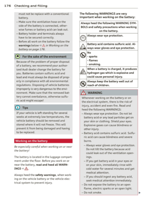 178
178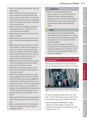 179
179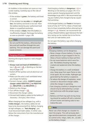 180
180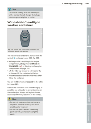 181
181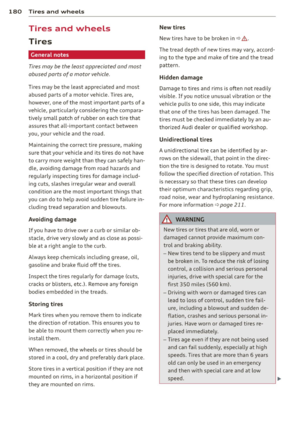 182
182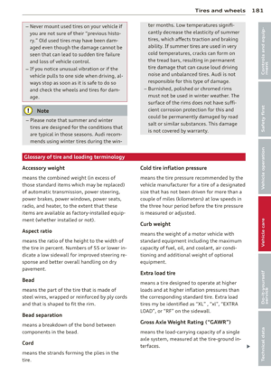 183
183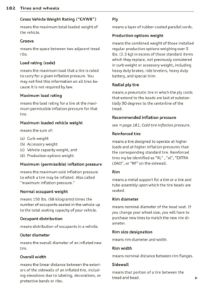 184
184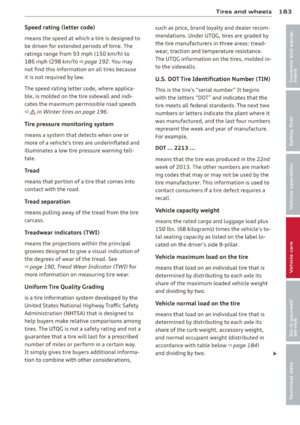 185
185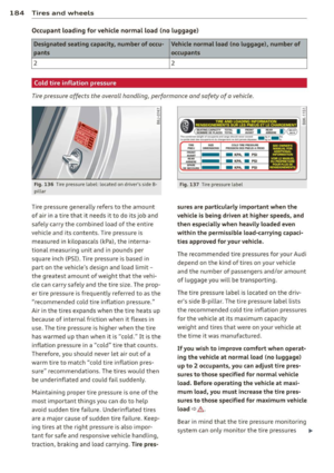 186
186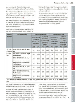 187
187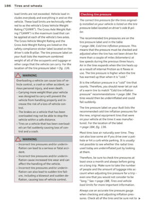 188
188 189
189 190
190 191
191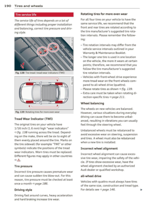 192
192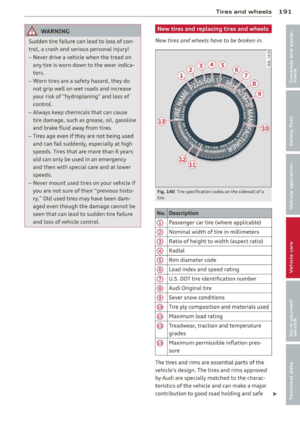 193
193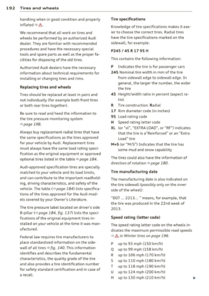 194
194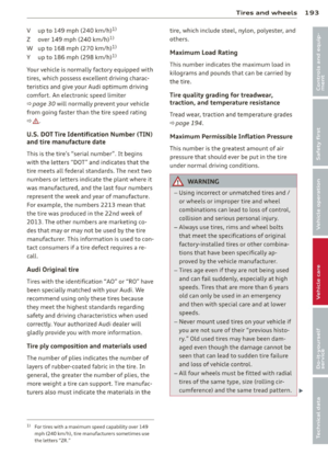 195
195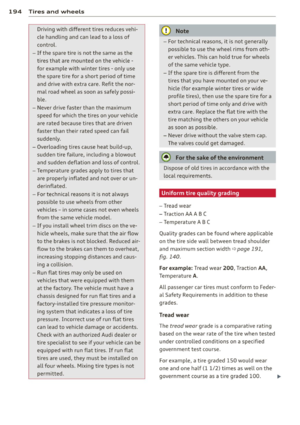 196
196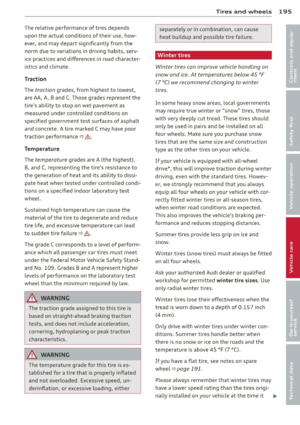 197
197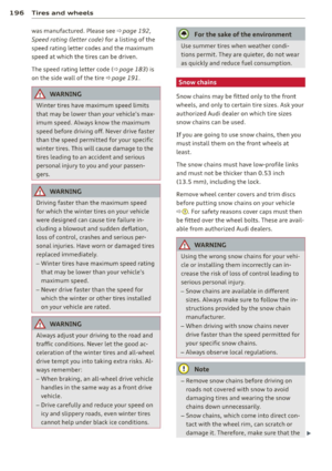 198
198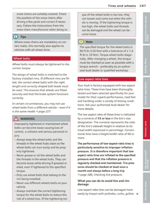 199
199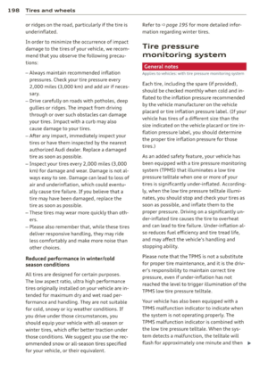 200
200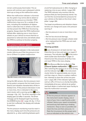 201
201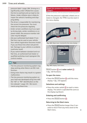 202
202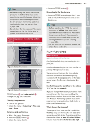 203
203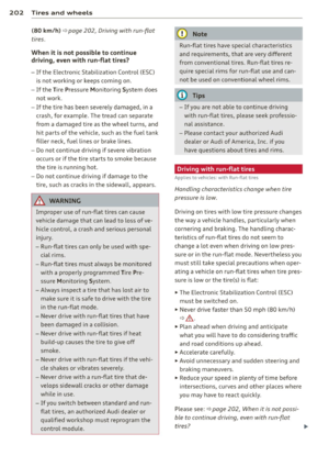 204
204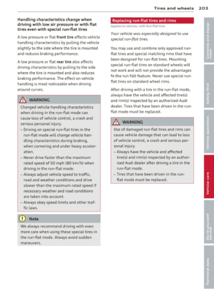 205
205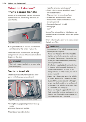 206
206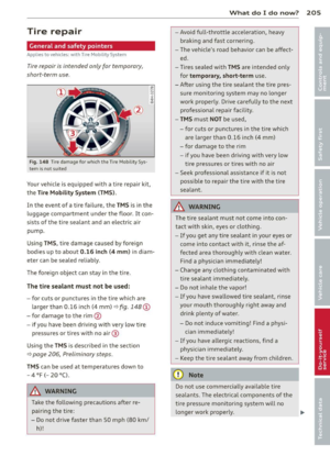 207
207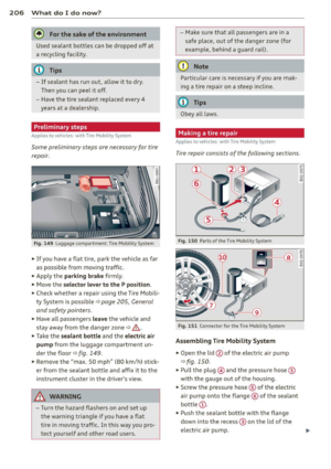 208
208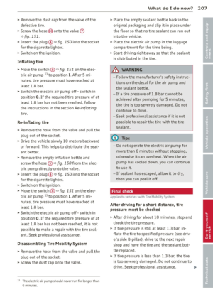 209
209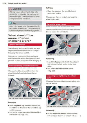 210
210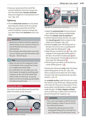 211
211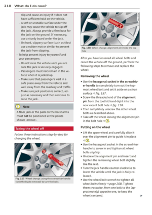 212
212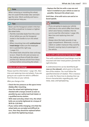 213
213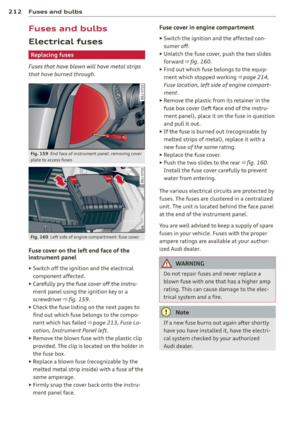 214
214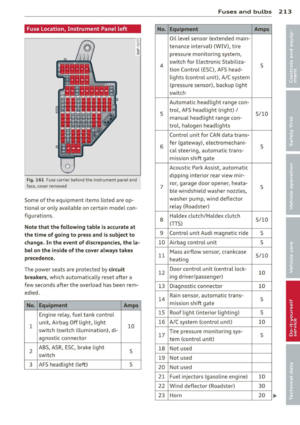 215
215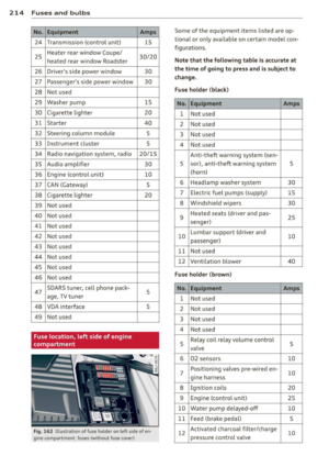 216
216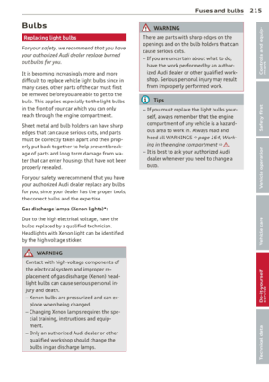 217
217 218
218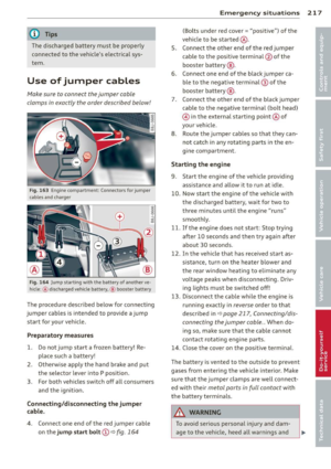 219
219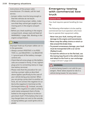 220
220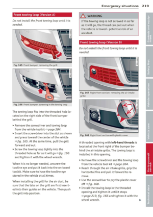 221
221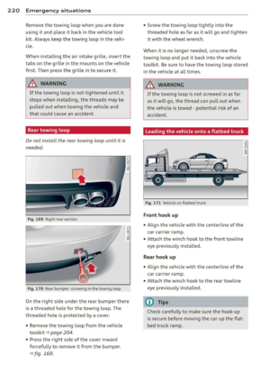 222
222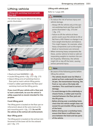 223
223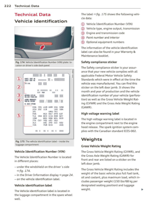 224
224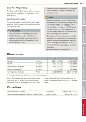 225
225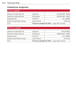 226
226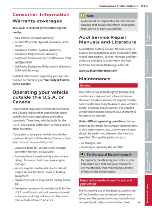 227
227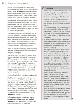 228
228 229
229 230
230 231
231 232
232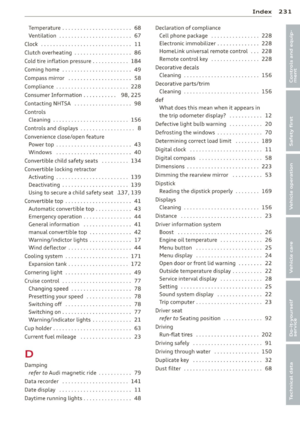 233
233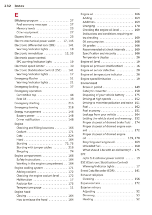 234
234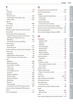 235
235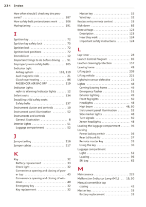 236
236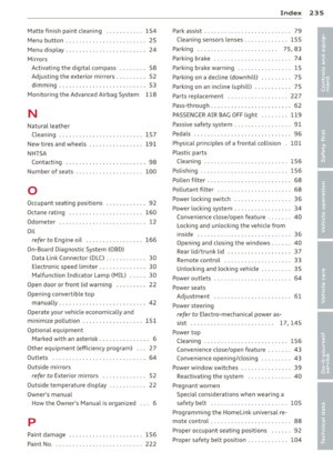 237
237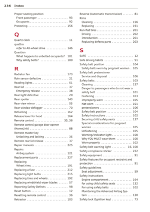 238
238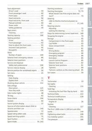 239
239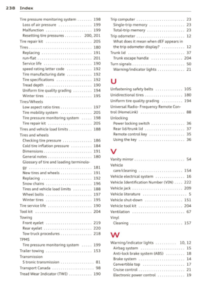 240
240 241
241 242
242 243
243