Page 217 of 244

Bulbs
Replacing light bulbs
For your safety, we recommend that you have
your authorized Audi dealer replace burned
out bulbs for you .
It is becoming increasingly more and more
difficult to replace vehicle light bulbs since in many cases, other parts of the car must first
be removed before you are able to get to the
bu lb. This appl ies especially to the light bu lbs
in the front of your car which you can on ly
reach through the engine compartment .
Sheet metal and bulb ho lde rs can have sharp
edges that can cause ser ious cuts, and parts
must be correctly taken apart and then prop
erly put back together to help prevent break
age of parts and long term damage from wa
ter that can enter housings that have not been
properly resealed.
F or your safety, we recommend that you have
your authorized Audi dealer replace any bulbs
for you, since your dealer has the proper tools,
the correct bu lbs and the expertise.
G as disc harge la mp s (X enon li ght s)*:
Due to the high electrical voltage, have the
bu lbs rep laced by a qualified technician.
H eadlights with Xenon l ight can be ident ified
by the high voltage sticker .
A WARNING
Contact with hig h-voltage components of
the electrica l system and improper re
placement of gas discharge (Xenon) head
light bulbs can cause serious personal in
jury and death .
- Xenon bulbs are pressurized and can ex plode when be ing changed.
- Chang ing Xenon lamps requires the spe
c ial train ing, instructions and equip
ment.
- Only an authorized Aud i dea ler or other
qualified workshop should change the
bulbs in gas discharge lamps .
Fuses and bulb s 215
A WARNING
There are parts with sharp edges on the
openings and on the bulb holders that can
cause ser ious cuts.
- If you are uncertain about what to do,
have the work performed by an author
ized Audi dealer or other qualified work
shop. Ser ious personal i nju ry may result
from imprope rly perfo rmed wo rk.
(D Tips
- If you must replace the light bulbs your
self, always remember that the eng ine
compartment of any vehicle is a hazard
ous area to work in. A lways read and
heed a ll WARN INGS
°* page 164, Work
ing in the engine comportment"*&. .
- It is best to ask your authorized Audi
dealer whenever yo u need to change a
bulb .
• -
•
Page 218 of 244

216 Emergency situations
Emergency situations
General
This chapter is intended for trained emer
gency crews and working personnel who
have the necessary tools and equ ipment to
perform these ope rations.
Starting by pushing or
towing
Q;) Note
Vehicle s with an automati c transmission
cannot be started by pushing or towing .
Starting with jumper
cables
If necessary, the engine can be started by
connecting it to the battery of another vehi
cle.
If the engine should fail to start because of a
discha rged or wea k batte ry, the battery can be
connected to the battery o f
another vehicle,
using a
pair of jumper cables to start the en
g ine .
Jumper cables
Use only jumper cab les of sufficiently
large cross section to safely carry the starter
cur rent. Refer to the manufacturer's specifica
ti ons.
Use on ly jumper cables which have
insulated
termina l clamps and are properly marked for
d istinction :
plus(+) cable in most cases colo red red
minu s(-) cable
in most cases colo red black .
_& WARNING
Batterie s contain elec trici ty, a cid, and ga s.
Any of th ese c an cause ve ry seri ous or f ata l
inju ry . Follow the instructions below fo r
safe han dling of your ve hicle's battery.
- Alw ays s hield yo ur eyes and avoid lean
ing over the batte ry w henever possib le . -
A discharged battery can a lready freeze
at temperatures just be low 32 °F (0 °C).
Before connect ing a jumper cab le, the
frozen battery must be thawed com
p letely, othe rwise it cou ld explode .
- Do not allow batte ry acid to contact eyes
or skin . Fl ush any contacted a rea wi th
water immediat ely .
- Imp roper use of a booster battery to
s tart a vehicle may cause an explosion.
- Vehicle batter ies generate explosive gas
es . Keep sparks, flame and lighted ciga
rettes away from ba tte ries .
- Do not try to jump start a ny ve hicle w ith
a low ac id leve l in the battery .
- The vo ltage of the booster batte ry m ust
a lso have a 12-Vo lt rat ing . The capacity
(A h) of the booster batte ry should not b e
lowe r than that of the discharged bat
tery . U se o f batt erie s of d iffe ren t voltage
or subs tanti ally diffe ren t "Ah" rat ing
may c ause an exp losion and person al in
ju ry .
- N ever ch arge a fr ozen bat te ry. Gas t rap
ped in the ice may ca use an ex plosion .
- N ever ch arge o r use a batt ery th at has
been fro zen. T he battery case may have
be weakened.
- Us e of batt erie s of di ffere nt vo lta ge or
substan tially differen t ca pa city (Ah) rat
i ng may cause an exp losion and injury.
T he capac ity (Ah) of the booster battery
should not be lower than that of the dis
charged batte ry.
- Before you check anything in the engine
compartment, always read and heed a ll
W ARNI NGS
c::;,page 164, Working in the
engine compartment .
@ Note
-App lying a hig her voltage booster ba t
tery will cause expens ive damage to se n
sitive electronic components, such as
cont ro l units , relays, rad io, etc.
- There must be no electrical contact be
twee n the vehicles as otherwise current
cou ld already start to flow as soo n as th e
posi tive (+) term inals are connect ed. ""
Page 219 of 244

@ Tips
The discharged battery must be properly connected to the vehicle's electrical sys
tem.
Use of jumper cables
Make sure to connect the jumper coble
clomps in exactly the order described below!
Fig. 163 Eng ine compartme nt: Co nnecto rs for jumper
cables and charger
F ig . 164 Jump start ing with the battery of another ve
h icle: @discharged ve hicle batte ry, @ booste r battery
The procedure described below for connecting
jumper cables is intended to provide a jump
start for your veh icle.
Preparatory me asures
1. Do not jump start a frozen battery! Re
place such a battery!
2 . Otherwise apply the hand brake and put
the selector leve r into P pos ition.
3. For both vehicles swi tch off all cons umers
and the ignit ion.
Conn ecting /disconnecting the jumper
cable .
4. Con nect one end of the red jumper cable
on the
jump st a rt bo lt @ ¢ fig. 164
Emergenc y situ ation s 21 7
(Bolts under red cover = "positive") o f the
vehicle to be started @.
5 . Connect the other end of the red jumper
cable to the positive terminal @ofthe
booster battery @.
6 . Connect one end of the black jumper ca
ble to the negat ive terminal ® of the
booster battery @.
7. Co nnect the othe r end of the black jumper
c able to the negat ive termina l (bolt head)
@ in the external starting po int @ of
your vehicle.
8 . Route the jumper cables so that they can
not catch in any rotat ing parts in the en
gine compartment.
Sta rting th e engine
9. Sta rt the eng ine of the vehicle providing
assistance and allow it to run at idle.
10. Now start the engine of the vehicle with
the discharged battery, wait for two to
three minutes until the engine "runs"
smooth ly.
11. If the eng ine does not start: Stop try ing
after 10 seconds and then try aga in after
about 30 seconds.
12 . In the vehicle that has received sta rt as
s istance, tur n on the heate r blower and
the rear window hea ting to elim inate a ny
vo ltage peaks when disconnecting . Driv
ing lights must be switched off!
13 . Disconnect the cable while the engine is
runn ing exactly in
reverse order to that
described in<=>
page 217, Connecting/dis
connecting the jumper coble ..
When do
ing so, make sure that the cable cannot
contact rotating eng ine parts.
14 . Close the cove r on the posit ive termina l.
T he battery is vented to the outside to p revent
gases from enter ing the veh icle inter ior. Make
s ur e that the jumper clamps a re well connec t
ed with their
me tal parts in full contact with
the battery terminals.
A WARNING
To avoid serious personal injury and dam
age to the vehicle, heed all warnings and
Page 220 of 244

218 Emergency sit uat ions
instructions of the jumper cable
manufacturer. If in doubt, call for road
service.
- Jumper cables must be long enough so
that the vehicles do not touch.
- When connecting jumper cables, make
sure that they cannot get ca ught in any
moving parts in the eng ine compart
ment.
- Before you check anything in the engine
compartment, always read and heed all
WARNINGS
¢ page 164, Working in the
engine compartment.
@ Note
Improper hook-up of jumper cables can ru
in the generator.
- Always connect POSITIVE(+) to POSI TIVE(+), and NEGATIVE( -) to NEGATIVE
( - ) ground post of the battery manager
control unit.
- Check that all screw plugs on the battery
cells are screwed in firmly . If not, tighten
plugs prior to connecting clamp on nega
tive battery terminal.
- Please note that the procedure for con nect ing a jumper cable as desc ribed
above applies spec ifically to the case of
you r vehicle being j ump s tarted. When
you are giv ing a jump star t to anothe r ve
hicle, do
not connect the negat ive (-) ca
ble to the negative(-) terminal on the
discharged battery ©- Instead, securely
connect the negative(-) cable to either a
solid metal component that is firmly
bo lted to the engine block or to the en
gine block itself. If the battery that is be
i ng charged does not vent to t he outside,
escaping batte ry gas cou ld ig nite and ex
plode!
Emergency towing
with commercial tow
truck
General hints
Your Audi requires special handling for tow
ing.
T he following information is to be used by
commercial tow truck operators who know
how to operate their equipment safely.
- Nev er tow your Audi , towing will cau se
damage to the engine and tr an smi ssion .
- Ne ver wrap th e safet y chain s or winch ca
ble s ar ound the brak e lines.
- To prevent unne ces sary damage , your Audi
must be tran sp o rt ed with a car carrier
(flatbed truck ).
- To load th e vehi cle on t o the flat bed , u se
the t owing loop found in t he vehicle tools
and attach to the front o r rear ancho rage
¢page 219 and ¢page 220 .
A WARNING
-A vehicle being towed is not safe for pas-
sengers. Never allow anyone to ride in a
vehicle be ing towed, for any reason.
-
Page 221 of 244

Do not install the front towing loop until it is
needed.
Fig. 165 Fro nt bumper: removing t he grill
Fi g. 166 Fron t bumper: screw ing in t he tow in")
Front towing loop (Version A)
Do not install the front towing loop until it is
needed.
Fig. 165 Fro nt bumper: removing t he grill
Fi g. 166 Fron t bumper: screw ing in t he tow ing loop
The tow ing loop fits into the threaded hole lo
cated on the righ t side of the fron t bumper
behind the grill.
"' Remove the screwdriver and towing loop
from the vehicle tool kit ¢
page 204.
"'Inse rt the screwdrive r into the slo t as shown
and press toward the center of the vehicle
c;, fig. 165 . At the same time, pull the grill
forward and out.
"' Screw the towing loop tightly into the
threaded hole as far as it will go
c;, fig. 166
and tighten it w ith the wheel wrench .
When it is no longer needed, unscrew the
towline eye and put it back into the on -board
toolkit . Make sure to have the towline eye
stored in the ve hicle at all times .
When insta lling the gr ill for the air duct, be
sure that the tabs on the grill are first insert
ed into their guides on the veh icle. Then push
the gr ill into position .
Emergency situations 219
A WARNING
If the tow ing loop is not screwed in as far
as it will go, the thread can pull out when
the vehicle is towed -potential risk of an
accident .
Front towing loop (Version B)
Do not install the front towing loop until it is
needed.
Fig. 167 Right front sectio n: remov ing the air intake
g ri lle
Fig. 168 Right fro nt sect ion w it h plast ic cove r
A threaded opening w ith left-hand threads is
located at the front right of the bumper be·
hind the air intake grille. The towing loop is
i nstalled in this opening .
"' Remove the screwdr iver and the towing loop
from the vehicle tool kit
c:> page 204.
"'Reach through the air intake grille, grip the
hor izonta l fins and pull it forward to re·
move .
"' Use the screwdrive r to pry the plastic cover
offr=;,fig. 168.
"'Install the towing loop in the threaded
opening and tighten it unt il it stops
c;, page 219, fig . 166 and tighten it with the
wheel wrench.
...
Page 222 of 244

220 Emergency situations
Remove the towing loop when you are done
using it and place it back in the vehicle tool
kit. Always keep the towing loop in the vehi
cle .
When installing the air intake grille, insert the
tabs on the grille in the mounts on the vehicle
f ir st. Then press the grille in to secure it.
A WARNING
If the towing loop is not tightened until it
stops when installing, the threads may be
pulled out when tow ing the vehicle and
that could cause an accident .
Rear towing loop
Do not install the rear towing loop until it is
needed.
Fig. 169 Right rear section
Fig. 170 Rear bum per: screw ing in the towing loop
On the r ight side under the rear bumper there
is a threaded hole for the towing loop. The
threaded hole is protected by a cover.
"' Remove the towing loop from the vehicle
toolkit ~
page 204 .
"'Press the right side of the cover inward
forcefully to remove it from the bumper.
~fig. 169.
"' Screw the towing loop tightly into the
threaded hole as far as it will go and tighten
it with the wheel wrench .
When it is no longer needed, unscrew the
towing loop and put it back into the vehicle
toolkit . Be sure to have the towing loop stored
in the vehicle at all times.
A WARNING
-If the towing loop is not screwed in as far
as it will go, the thread can pull out when
the veh icle is towed -potent ial risk of an
accident.
Loading the vehicle onto a flatbed truck
Fig. 171 Vehicle on flatbed t ruck
Front hook up
"' Align the vehicle with the centerline of the
car carrier ramp .
"' Attach the winch hook to the front towline
eye previously installed.
Rea r hook up
"' Align the vehicle with the centerline of the
car carrier ramp.
"' Attach the winch hook to the rear towline
eye previously installed.
(D Tips
Check carefu lly to make sure the hook-up
is secure before moving the car up the flat
bed truck ramp.
Page 223 of 244
")
Lifting vehicle
lifting with workshop hoist and with
floor jack
The vehicle may only be lift ed at the lifting
poin ts illustra ted.
F ig. 1 72 Rear lift ing point (right side)
Fi g. 1 73 Front lift ing po int fright side)
• Rea d and heed W ARNI NG¢,&. .
• Locate lifting points ¢fig . 172 Qfig . 173 .
• Adjust lifting arms of workshop hoist or
floor jac k to match vehicle lifting points.
• Inse rt a r ubber pad between the floor jack/
workshop hoist a nd the lifting poi nts.
If you must lift your vehicle with a floor jack
to work underneath, be sure the vehicle is safely supported on stands intended for this
purpose.
Front lifting point
The lifting point is locate d on the f loor pan re
inforcement about at the same level as the
jack mounting point¢
fig. 173. Do not lift
the vehicle at the vertical s ill reinforcement .
Rear lifting point
The lifting poi nt is locate d on t he vertical rein
forcement of the lower sill for t he on boa rd
jack
Q fig. 172.
Emergency situations 221
lifting with vehicle jack
Refer to c::> page 2 09.
_&. WARNING
- To reduce t he risk of ser ious injury an d
ve hicl e damage.
- Alwa ys lift the vehicle only at t he spe
c ial w orkshop hoist and floor jack lift
p oin ts ill ust rated ¢
fig. 172 and
¢fig. 173.
-Fa il ure to li ft th e ve hicle a t these
p o ints co uld cau se the ve hi cle t o til t or
f all from a lift if there i s a cha nge in ve
h icl e weigh t distr ibuti on and b alan ce.
This mi ght h appen, fo r ex am ple, whe n
h eavy co mponent s such as the eng ine
b lock o r transmission are remove d.
- Wh en re m oving hea vy components li ke
these, anchor vehicle to hoist or ad d co r
respo nding wei ghts to maintain t he ce n
ter of gravity. Ot herwis e, th e ve hicle
might tilt or slip off the ho ist, caus ing
serio us pe rsonal in jury.
CI) Note
-Be aware of the following points before
lifting the vehicle:
- The vehicle should never be lifted or
jacked up from underneath the engine
oil pan, the transmission housing, the
front or rear axle or the body side
members. This could lead to seriou s
damage.
- To avoid damage to the underbody or
chassis frame, a rubber pad must be inserted between the floor jack and
the lift points.
- Before driving over a workshop hoist ,
check that the vehicle weight does not
exceed the permissible lifting capacity
of the hoist.
- Before driving over a workshop hoist ,
ensure that there is sufficient clear
ance between the hoist and low parts
of the vehicle.
-
Page 224 of 244
 plate: lo·
cat ion on driver s s ide dash panel
XXXXX XX · X -XXXX XXX xx")
222 Technical Data
Technical Data
Vehicle identification
Fig . 174 Vehicle Ident ification Number (VlN) plate: lo·
cat ion on driver 's s ide dash panel
XXXXX XX · X -XXXX XXX xx
r,"\__l f~ -11!111 · NII. ~ V!Hlll -llllll . NO.
IYP IT'fl'E
XXXXXXXX XX X XXXXXXXX
XXX XXX
XX XXXXXXX XX X X XX
XXX
KW XXX
®i ~~:f :l~~ XXXX XXX XXX
@+ ~~r= XXXX I XXXX XXX I XX M ,. AIIISl./ lflllllS
EOA 7D5 4 UB 6XM SSG 5RW
2E H JDZ llB l AS lBA
3FC 5MU 7Xl
FO A
9G3 OG7 O
YH OJF
TL6 3
KA BEH
UlA X9B QZ 7
l XW
8Q3 9Q8 82 4 020
7T6 CV 7 7KO 4X3 2K2
3L4 4 KC 3YO 4I3 502
lS A 7GB Q1A 4GQ
XX X XX X XX X XXXX
Fig. 175 The vehicle identificat ion label - inside the
luggage co mpa rtmen t
Vehicle Identification Number (VlN)
The Vehicl e Identification Number is located
in different p laces:
- under the w indshield on the driver 's side
c::>fig . 174.
-in the Driver Information display c::> page 24.
- on the vehicle identification label.
Vehicle identification label
The Vehicle identification label is located in
the luggage compartment in the spare whee l
well. T
he label
c::> fig. 175 shows the following vehi
cle data:
(D Vehicle Identificat ion Number (V IN)
@ . Vehicle type, engine output, transmission
® Engine and transm iss ion code
@ Paint number and interior
® Optional equipment numbers
The information of the vehicle identification
label can also be found in your Warranty
&
Maintenance booklet.
Safety compliance sticker
The Safety compliance sticker is your assur
ance that your new veh icle complies with all
applicable Federal Motor Vehicle Safety
Standards which were in effect at the time the
vehicle was manufactured. You can find this
sticker on the left door jamb. It shows the
month and year of product ion and the vehicle
identif ication number of your vehicle (perfora
tion) as well as the Gross Veh icle Weight Rat
ing (GVWR) and the Gross Axle Weight Rating
(GAWR).
High voltage warning label
The high voltage warning label is located in
the engine compartment next to the engine
hood re lease . The spark ignition system com
plies with the Canadian standard IC ES-002.
Weights
Gross Vehicle Weight Rating
The Gross Vehicle Weight Rat ing (GVWR), and
the Gross Axle Weight Rating (GAWR) for
front and rear are listed on a sticker on the
left door jamb.
The Gross Vehicle Weight Rat ing includes the
weight of the bas ic vehicle plus fu ll fuel tank,
o il and coolant, plus max imum load, which in
cludes passenger we ight (150 lbs/68 kg per
designated seating position) and luggage
weight. .,.
 1
1 2
2 3
3 4
4 5
5 6
6 7
7 8
8 9
9 10
10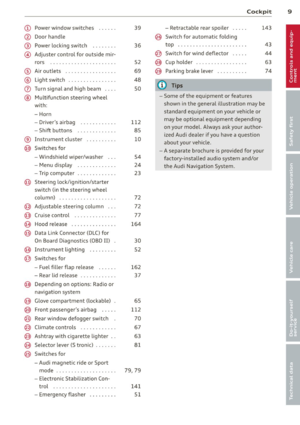 11
11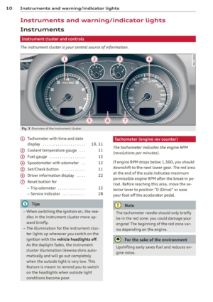 12
12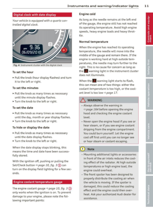 13
13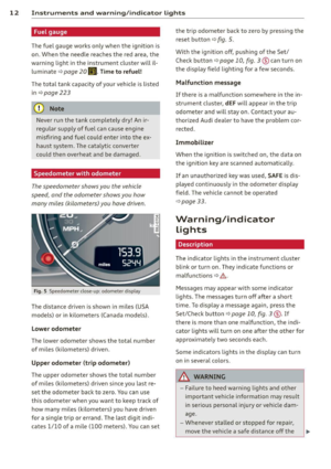 14
14 15
15 16
16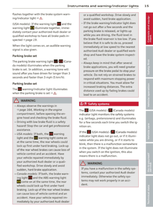 17
17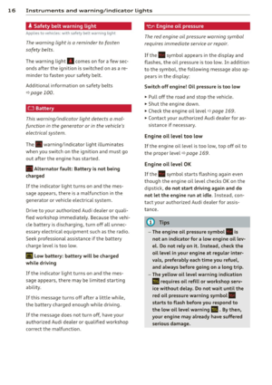 18
18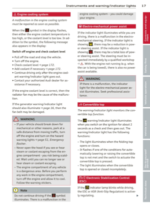 19
19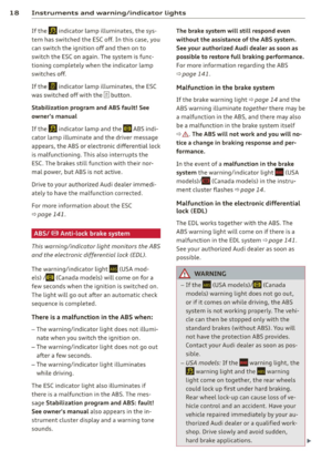 20
20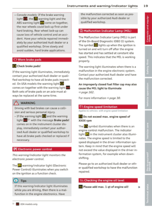 21
21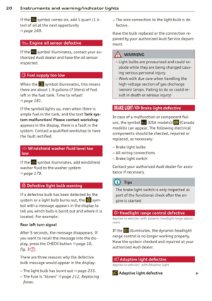 22
22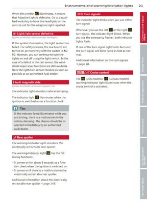 23
23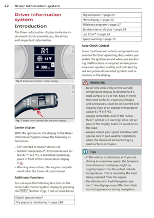 24
24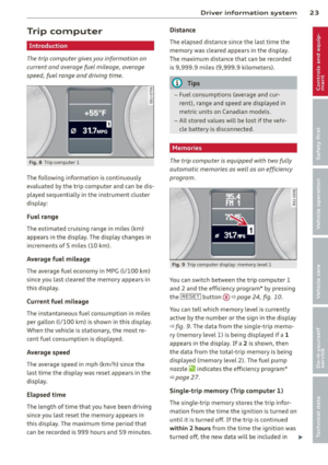 25
25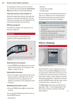 26
26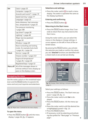 27
27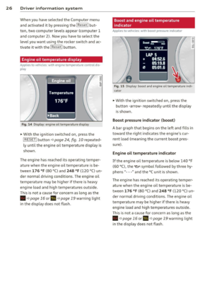 28
28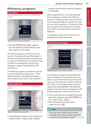 29
29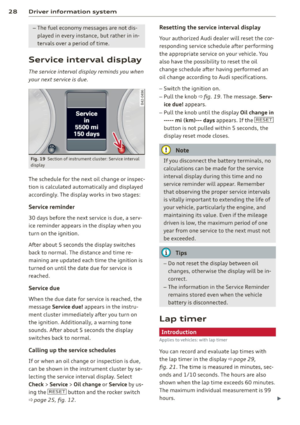 30
30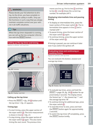 31
31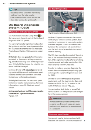 32
32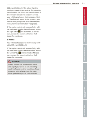 33
33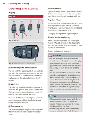 34
34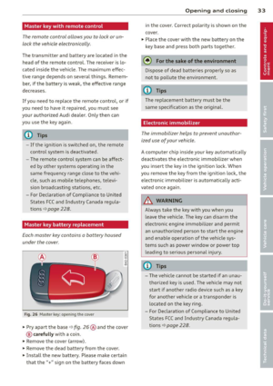 35
35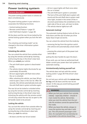 36
36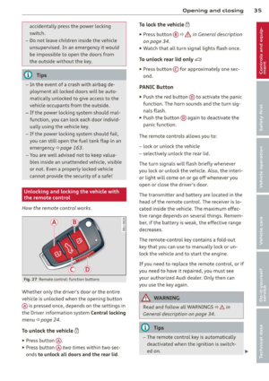 37
37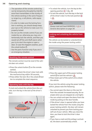 38
38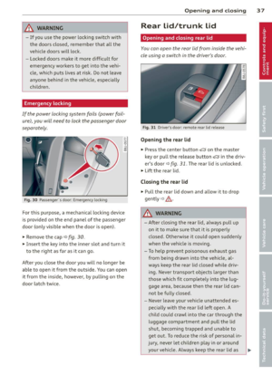 39
39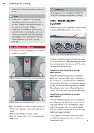 40
40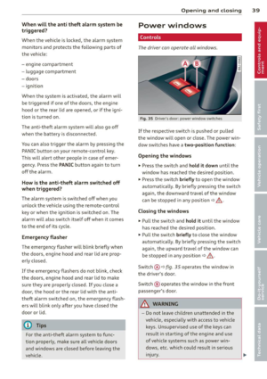 41
41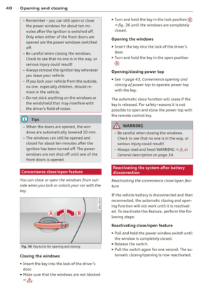 42
42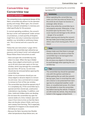 43
43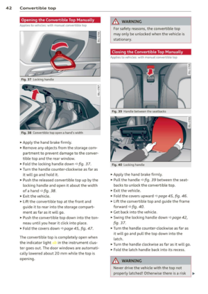 44
44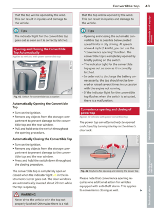 45
45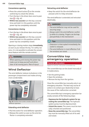 46
46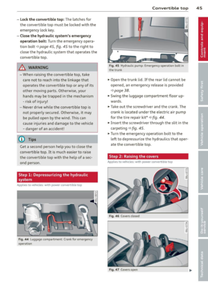 47
47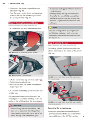 48
48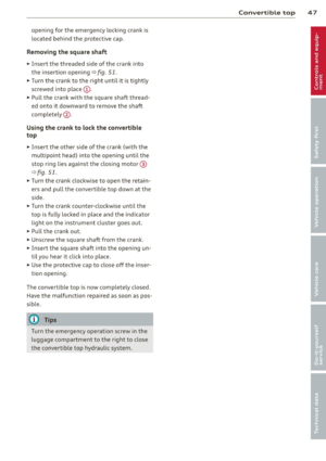 49
49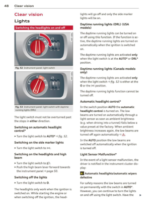 50
50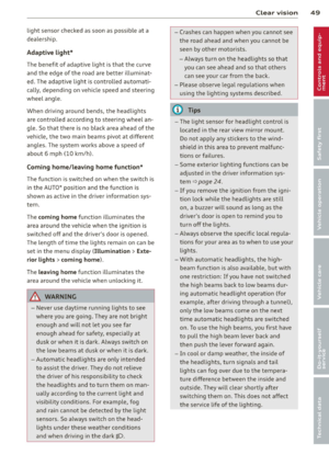 51
51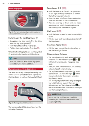 52
52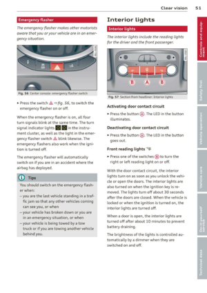 53
53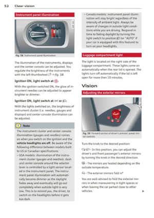 54
54 55
55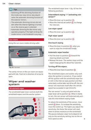 56
56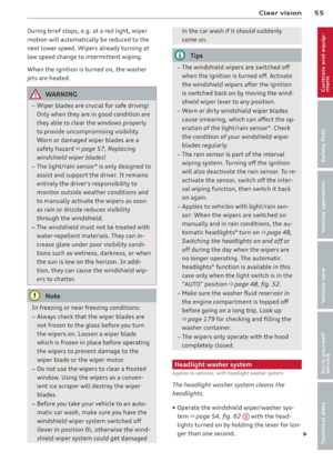 57
57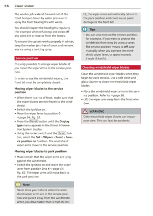 58
58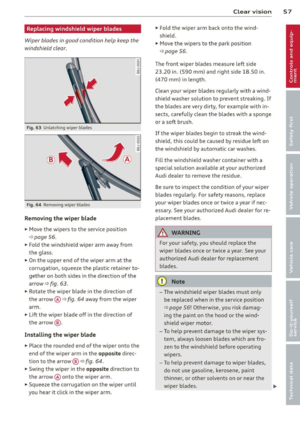 59
59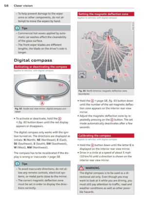 60
60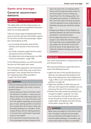 61
61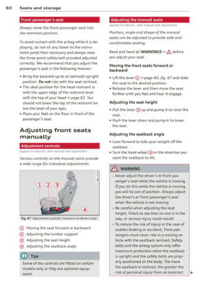 62
62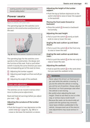 63
63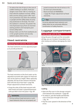 64
64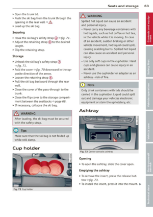 65
65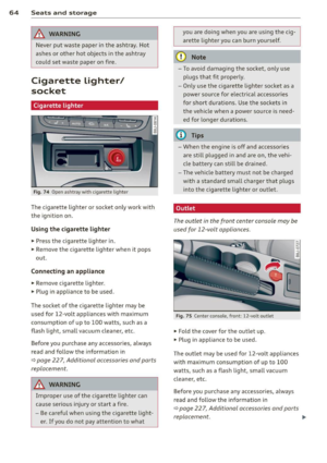 66
66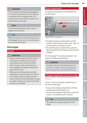 67
67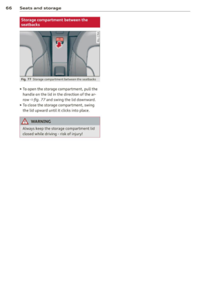 68
68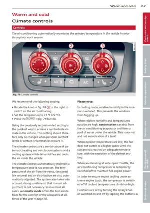 69
69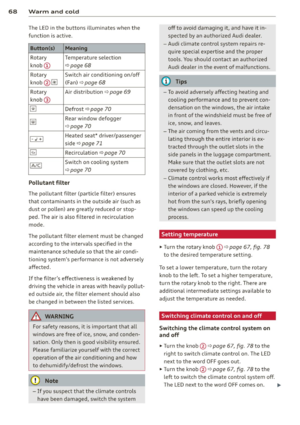 70
70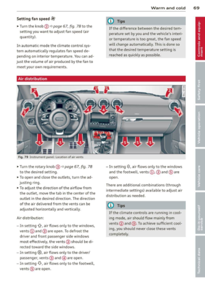 71
71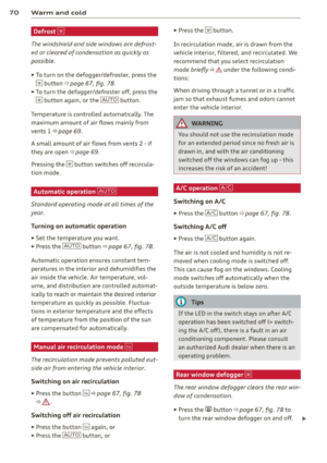 72
72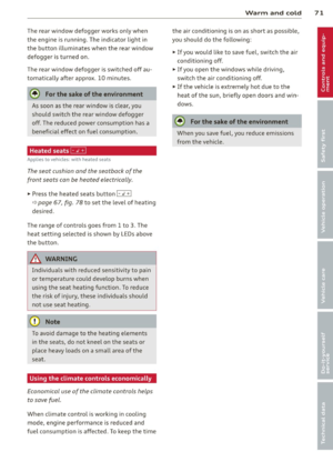 73
73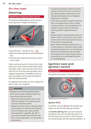 74
74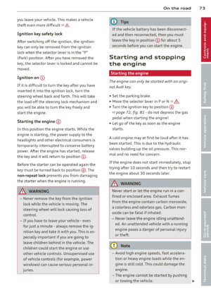 75
75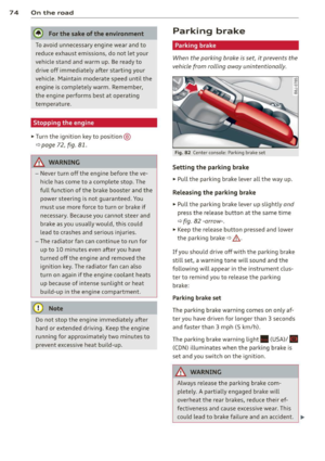 76
76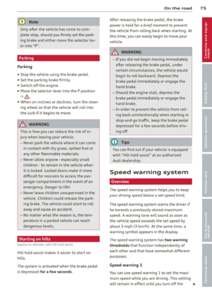 77
77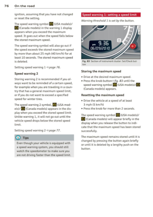 78
78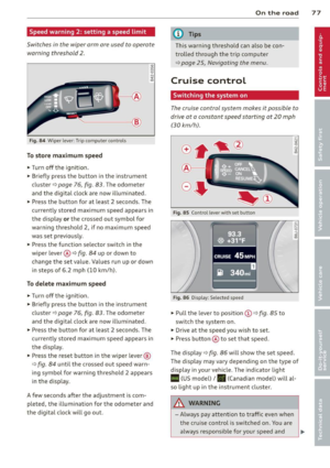 79
79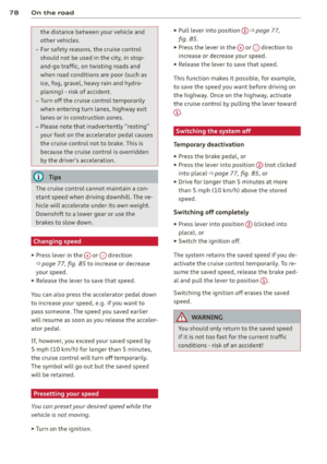 80
80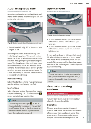 81
81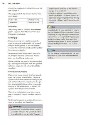 82
82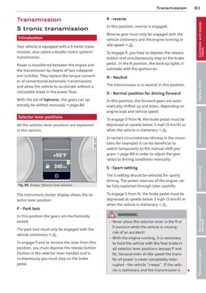 83
83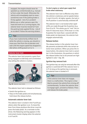 84
84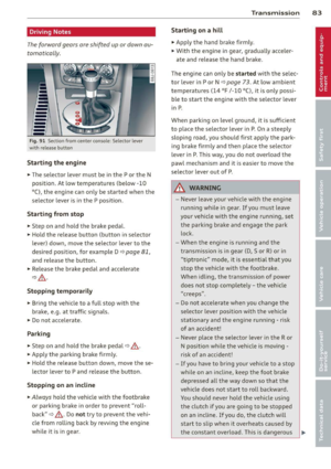 85
85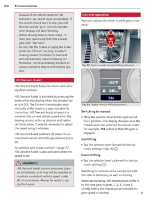 86
86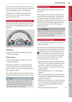 87
87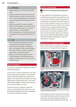 88
88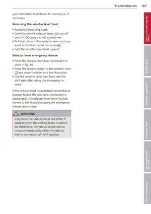 89
89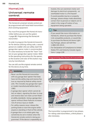 90
90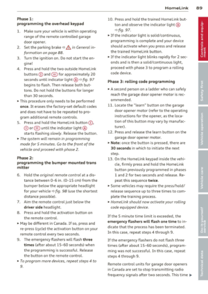 91
91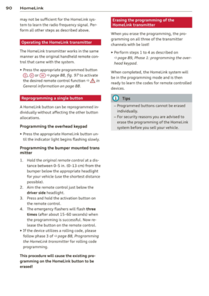 92
92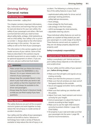 93
93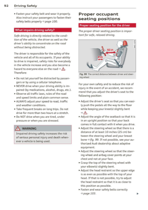 94
94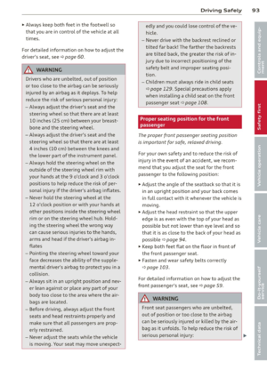 95
95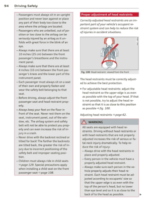 96
96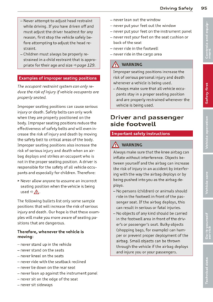 97
97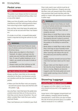 98
98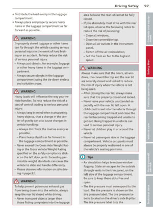 99
99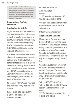 100
100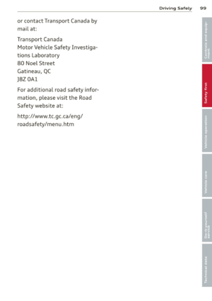 101
101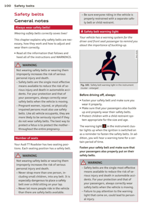 102
102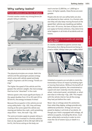 103
103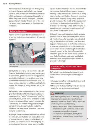 104
104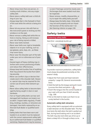 105
105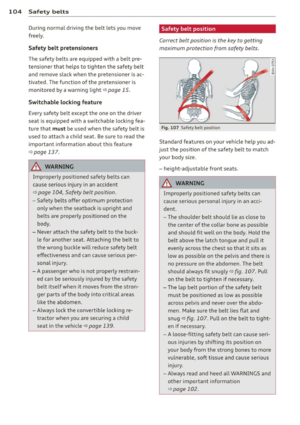 106
106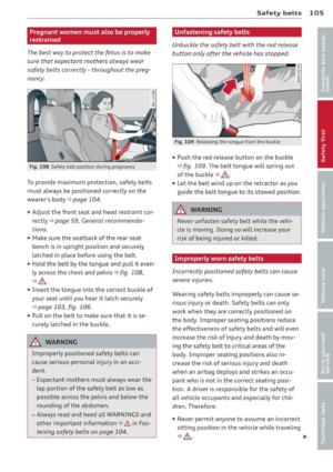 107
107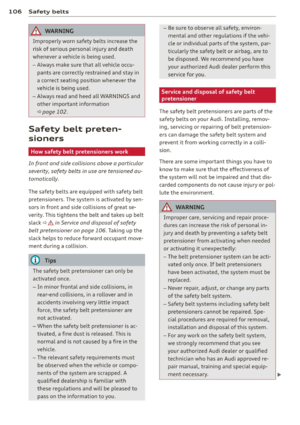 108
108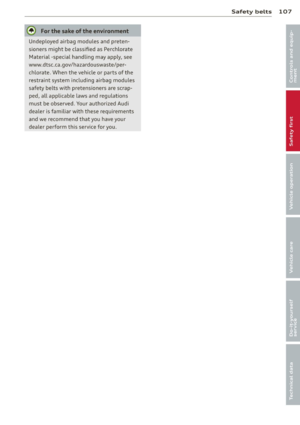 109
109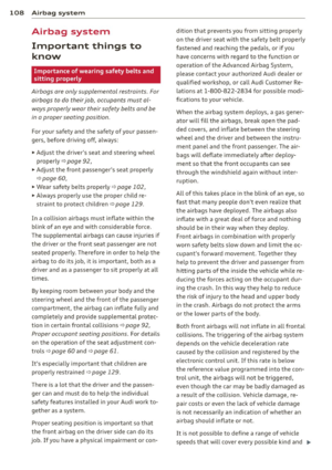 110
110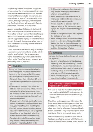 111
111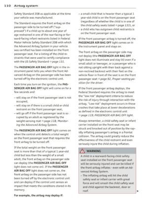 112
112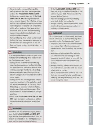 113
113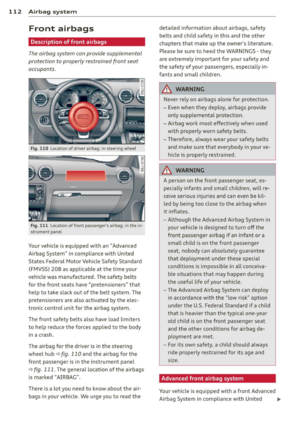 114
114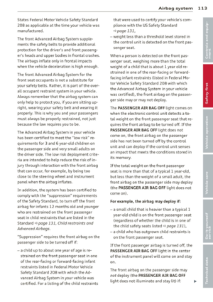 115
115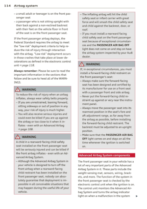 116
116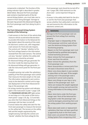 117
117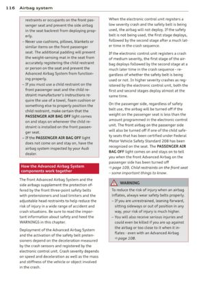 118
118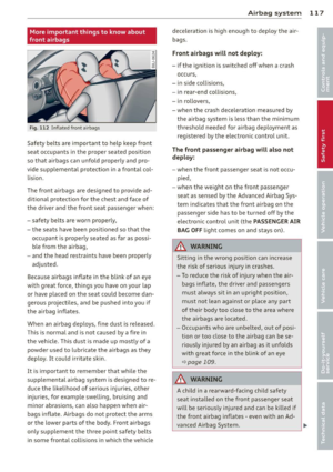 119
119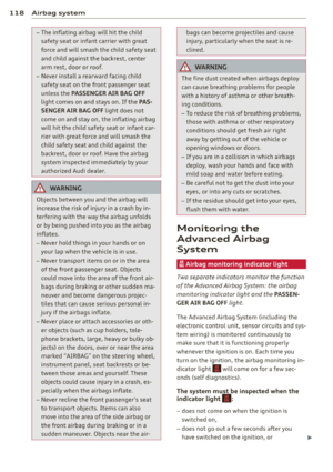 120
120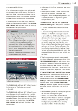 121
121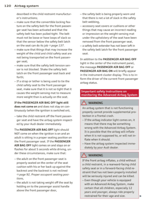 122
122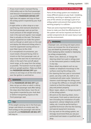 123
123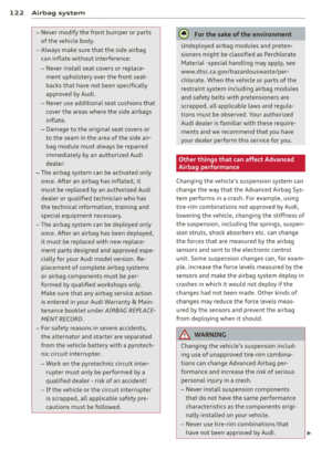 124
124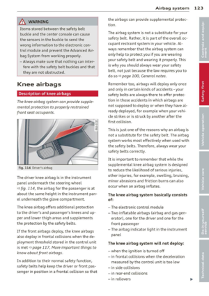 125
125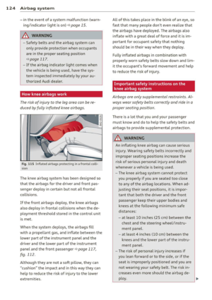 126
126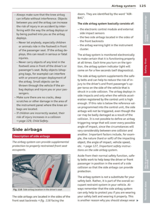 127
127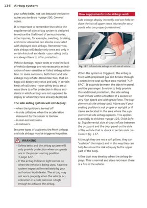 128
128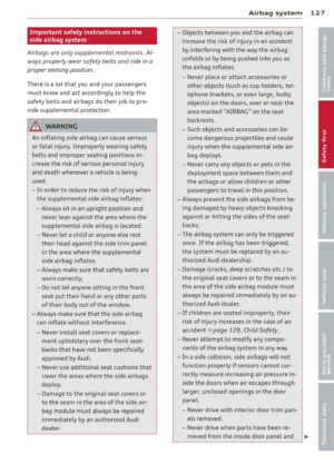 129
129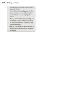 130
130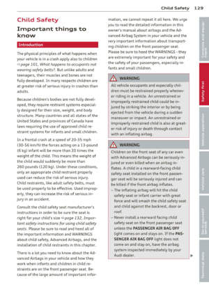 131
131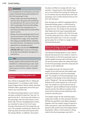 132
132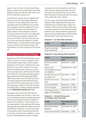 133
133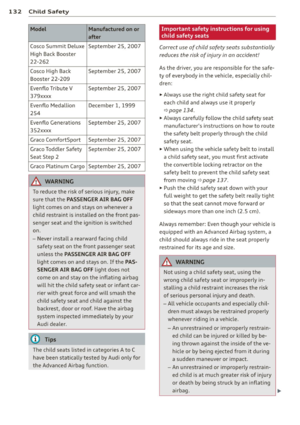 134
134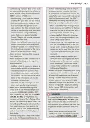 135
135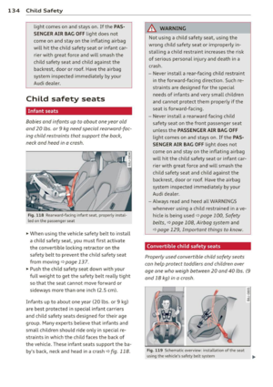 136
136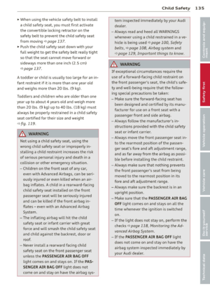 137
137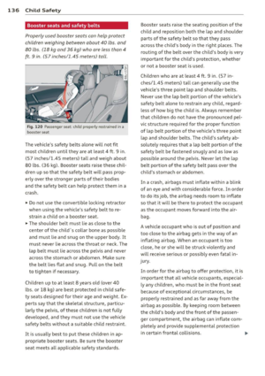 138
138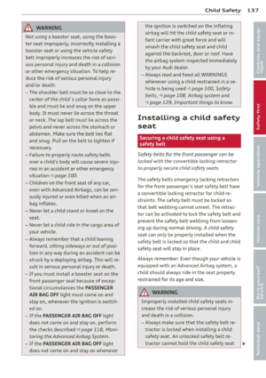 139
139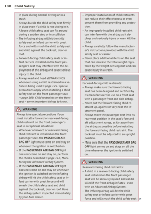 140
140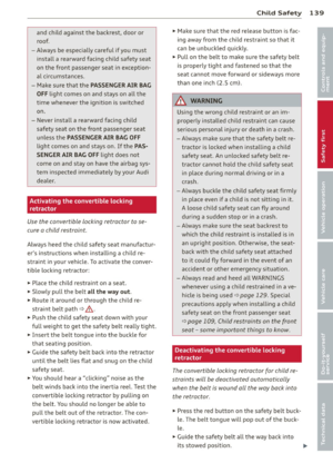 141
141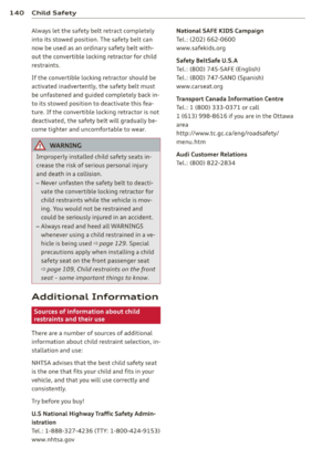 142
142 143
143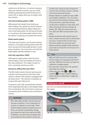 144
144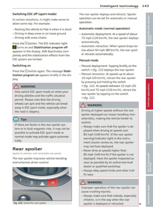 145
145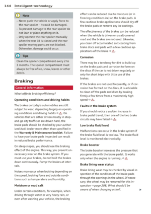 146
146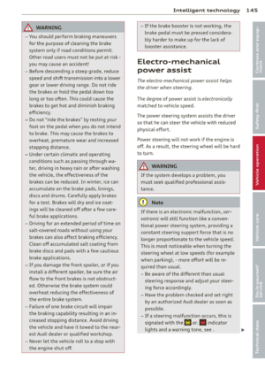 147
147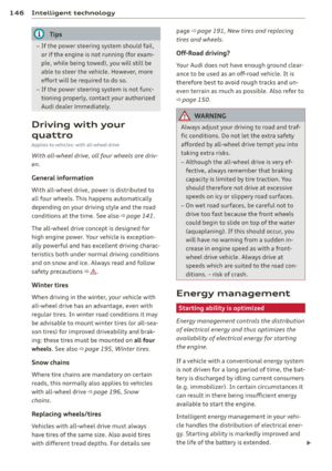 148
148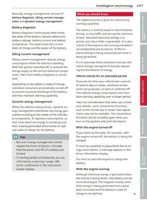 149
149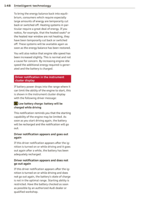 150
150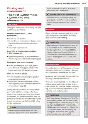 151
151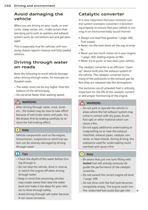 152
152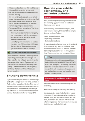 153
153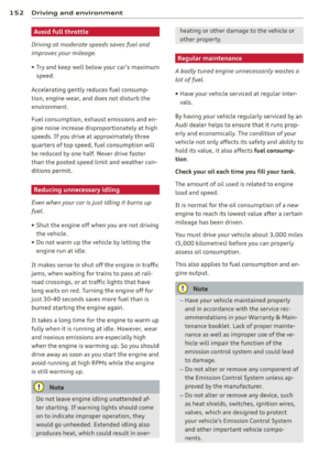 154
154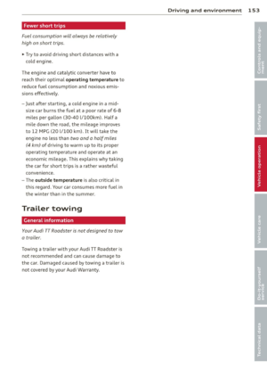 155
155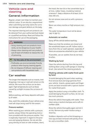 156
156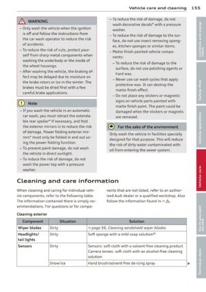 157
157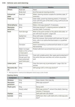 158
158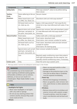 159
159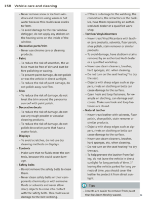 160
160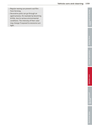 161
161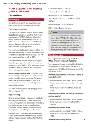 162
162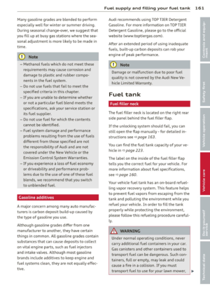 163
163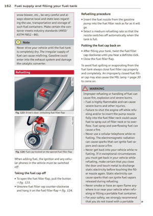 164
164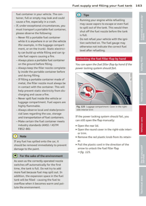 165
165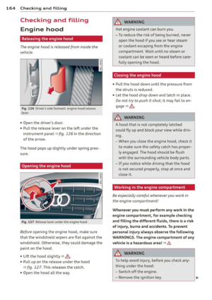 166
166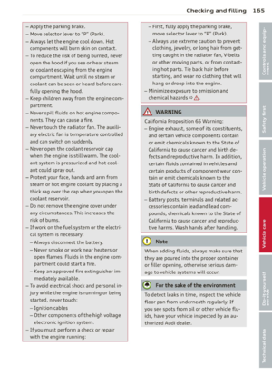 167
167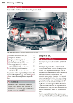 168
168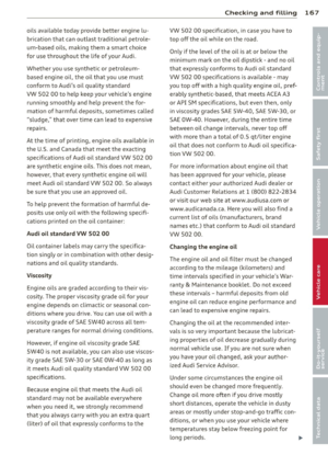 169
169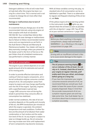 170
170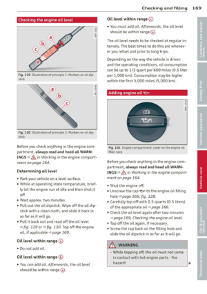 171
171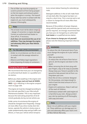 172
172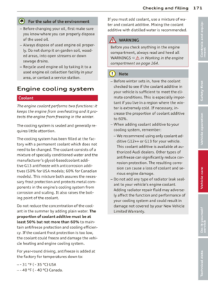 173
173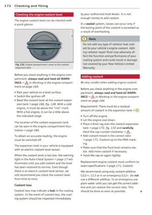 174
174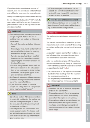 175
175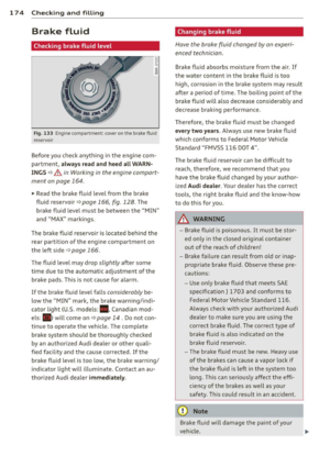 176
176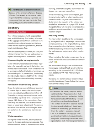 177
177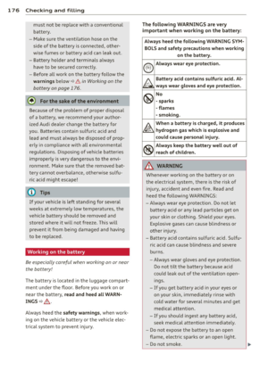 178
178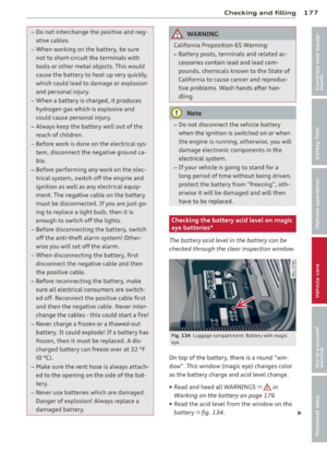 179
179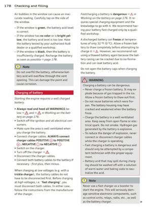 180
180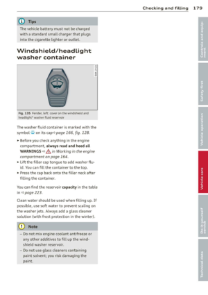 181
181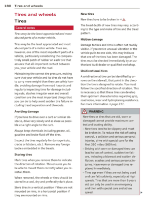 182
182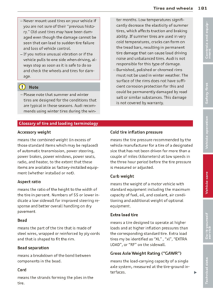 183
183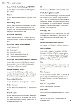 184
184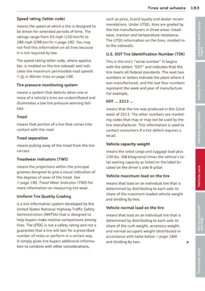 185
185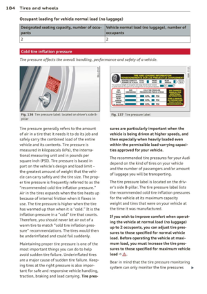 186
186 187
187 188
188 189
189 190
190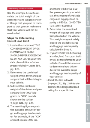 191
191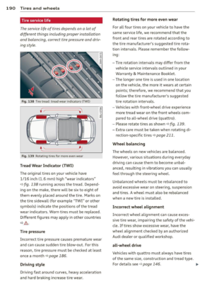 192
192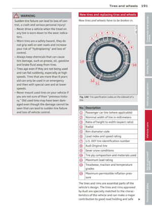 193
193 194
194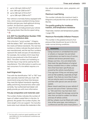 195
195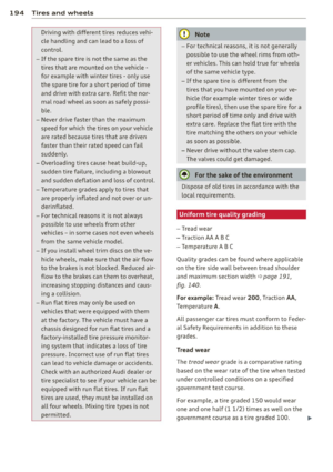 196
196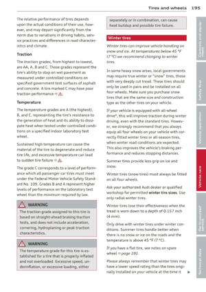 197
197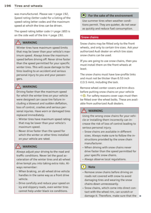 198
198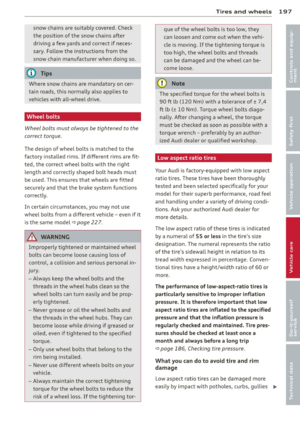 199
199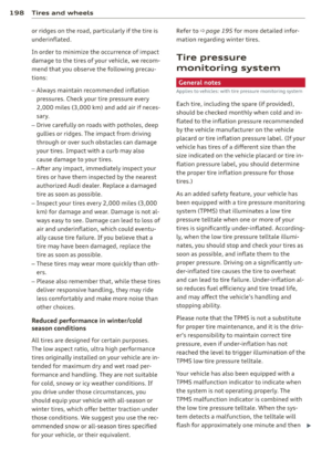 200
200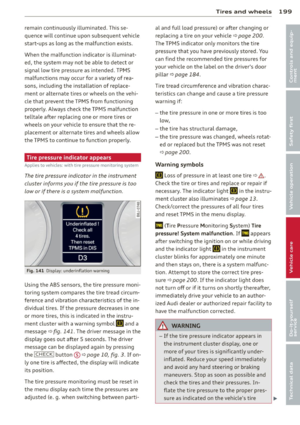 201
201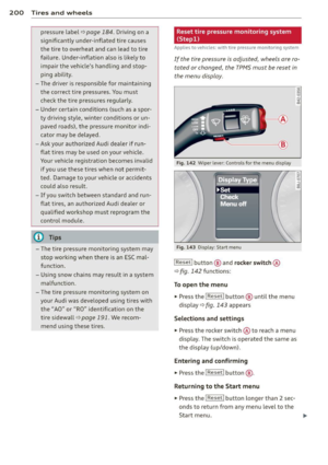 202
202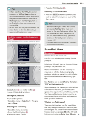 203
203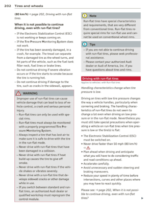 204
204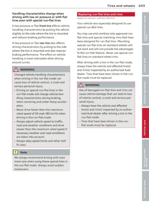 205
205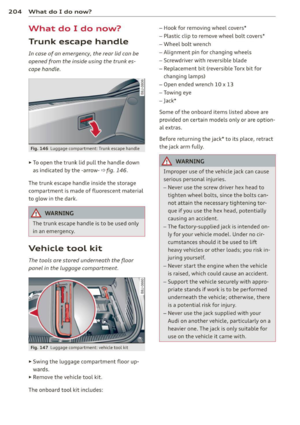 206
206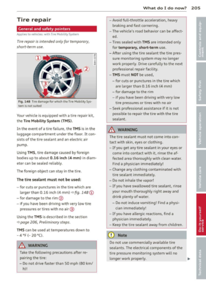 207
207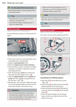 208
208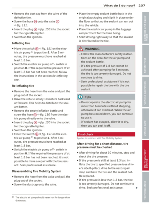 209
209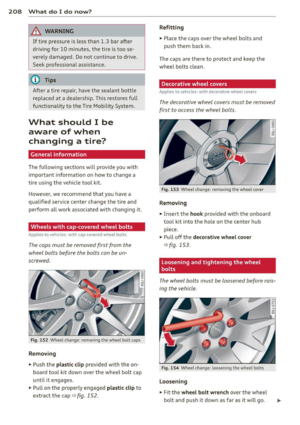 210
210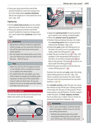 211
211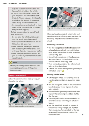 212
212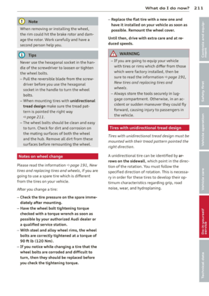 213
213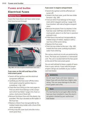 214
214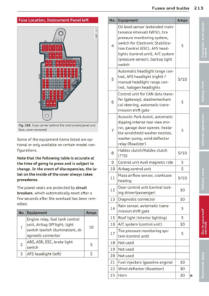 215
215 216
216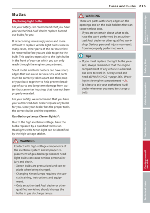 217
217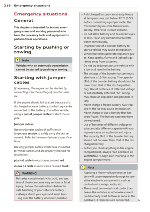 218
218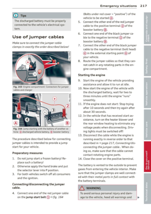 219
219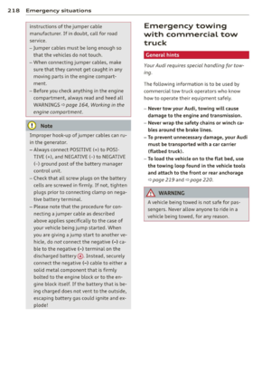 220
220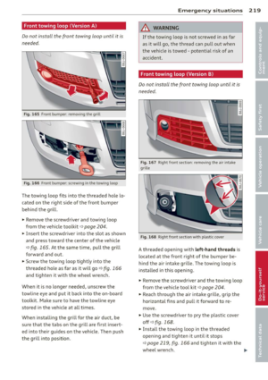 221
221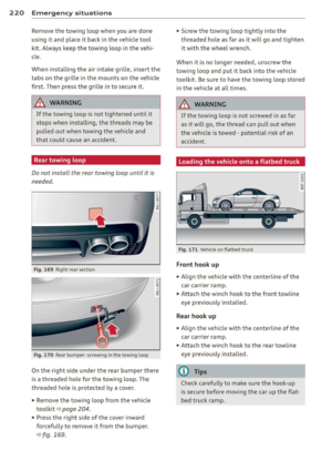 222
222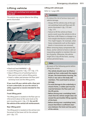 223
223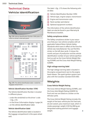 224
224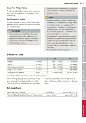 225
225 226
226 227
227 228
228 229
229 230
230 231
231 232
232 233
233 234
234 235
235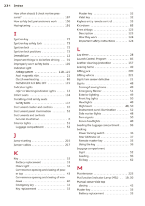 236
236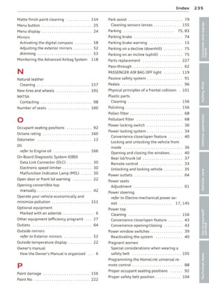 237
237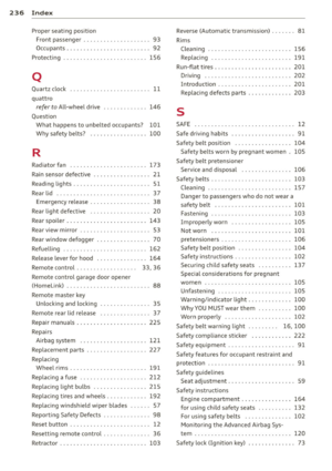 238
238 239
239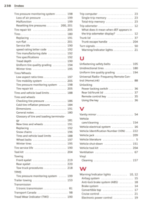 240
240 241
241 242
242 243
243