Page 129 of 216

System conditioned automatic start-upRead and observe
on page 124 first.
When the engine is off, the system can automatically start the engine before
the desired journey continues. The possible reasons for this are, for example:
› The vehicle has begun to roll, e.g. on a slope.
› The brake pedal has been actuated several times.
› The current consumption is too high.
Manually deactivating/activating
Fig. 126
Button for the START-STOP sys-
tem
Read and observe on page 124 first.
Deactivate/activate
›
Press the button
» Fig. 126 .
When start-stop mode is deactivated, the warning light in the button illumi-
nates.
Note
If the system is automatically deactivated when the engine is turned off, then
the automatic start process takes place.
Information messages
Read and observe
on page 124 first.
The warning symbols are shown in the instrument cluster display. Start the engine manually!
START MANUALLY
One of the conditions for automatic engine start is not satisfied or the driver's
seat belt is not fastened. The engine must be started manually.
On vehicles with the starter button the ignition is turned off by the first press
of the start button, only after pressing for the second time is the start process
initiated.
Error: start-stop system
START STOP ERROR
A system error is present. Seek help from a specialist garage.
Fatigue detection (break recommendation)
Introduction
This chapter contains information on the following subjects:
Function
126
Information messages
127
The fatigue detection system (hereinafter referred to only as system) recom-
mends the driver taking a break from driving when, because of the driver's
steering behaviour, driver fatigue can be detected.
WARNING■ For the driving ability is always the driver's responsibility. Never drive if
you feel tired.■
The system may not detect all cases where a break is needed.
■
Therefore, take regular, sufficient breaks during long trips.
■
There will be no system warning during the so-called micro-sleep.
Note
■ In some situations, the system may evaluate the driving incorrectly and thus
mistakenly recommend a break (e.g. sporty driving, adverse weather condi-
tions or poor road conditions).■
The system is designed primarily for use on motorways.
Function
Read and observe
on page 126 first.
From the start of the journey, the system evaluates steering behaviour. If,
while driving, there have been changes in the steering behaviours that are
evaluated by the system as indicating possible fatigue, a break recommenda-
tion is issued.
126Driving
Page 130 of 216

The system evaluates steering behaviour and recommends a break at speeds
of 65 - 200 km/h.
The system detects a break from driving when one of the following condi-
tions is met.
› The vehicle is stopped and the ignition switched off.
› The vehicle is stopped, the seat belt removed and the driver's door opened.
› The vehicle is stopped for more than 15 minutes.
If none of these conditions are met or if the driving style is not changed, the
system recommends a driving break again after 15 minutes.
The system can be activated/deactivated in the Infotainment » operating in-
structions for Infotainment , chapter Vehicle settings (CAR button) .
Information messages
Read and observe
on page 126 first.
The icon appears and the following message for a few seconds in the display
of the instrument cluster .
Fatigue detected. Take a break!
DRIVER ALERT TAKE A BREAK
An audible signal is also emitted.
Tyre pressure monitoring
Introduction
This chapter contains information on the following subjects:
Save tyre pressure values
127
Save tyre pressure values and infotainment display
128
Save tyre pressure values by pressing a button
128
The tyre pressure monitoring function monitors (hereinafter referred to only as
a system) the tyre pressure while driving.
When changing the tyre inflation pressure, the warning light illuminates in
the instrument cluster and an audible signal is heard.
Information on the procedure for the indication of change in tyre pressure val- ues » page 37 .
The system can only function properly if the tyres have the prescribed tyre
pressure and this pressure values are stored in the system.
WARNING■ The correct tyre pressure values is always the driver's responsibility. The
tyre pressure should be checked regularly » page 162.■
The system cannot warn in case of very rapid loss of tyre pressure, e.g. in
the event of a sudden puncture.
Save tyre pressure values
Read and observe
on page 127 first.
The tyre pressure valuesare always stored in the system, if one of the follow-
ing events is present.
› Change of tyre pressure values.
› Change one or more wheels.
› Change in position of a wheel on the vehicle.
› The warning light
in the instrument cluster.
The storage of the tyre pressure values depends on equipment, either in the
infotainment or by pressing a button.
WARNINGBefore storing the tyre pressures they must be inflated to the specified in-
flation pressure » page 162. If incorrect pressure values are storedthe sys-
tem may not warn even with a tyre pressure that is too low.
CAUTION
The tyre pressure values should be stored every 10 000 km or once a year to
ensure proper system function.127Assist systems
Page 131 of 216

Save tyre pressure values and infotainment displayFig. 127
Key for storing the pressure val-
ues / example of the display: the
system indicates a pressure
change in the front left tyre
Read and observe on page 127 first.
›
Inflate all of the tyres to the specified inflation pressure.
›
Switch on the ignition.
›
The Infotainment switches on.
›
Press the button
→
→ to activate vehicle status .
›
By using the function keys
select the menu item
Tyre Press. Loss Indica-
tor .
›
Press the button
SET » Fig. 127 .
In addition, follow the instructions that appear on the display.
A message in the display informs about the storage of the tyre pressure val-
ues.
Note
When a warning light in the instrument cluster appears, the affected tyre
can be displayed on the infotainment » Fig. 127.
Save tyre pressure values by pressing a button
Fig. 128
Button for storing the pressure
values
Read and observe on page 127 first.›
Inflate all of the tyres to the specified inflation pressure.
›
Switch on the ignition.
›
Press the symbol key
» Fig. 128 and keep it depressed.
The warning light
in the instrument cluster illuminates.
An acoustic signal sounds and the warning light extinguishes informs that the
storage of the tyre pressure values has taken place.
›
Press the symbol key
Release the symbol key
128Driving
Page 132 of 216

Hitch and trailer
Hitch
Introduction
This chapter contains information on the following subjects:
Description
129
Adjusting the ready position
130
A correctly set ready position
130
Assembling the bar ball - first step
131
Assembling the bar ball - second step
131
Check proper fitting
132
Removing the bar ball - first step
132
Removing the bar ball - second step
133
Accessories
133
The maximum trailer drawbar load is 50 kg.
WARNING■
Check that the ball head is seated correctly and is secured in the mount-
ing recess before starting any journey.■
Do not use the ball head if it is not correctly inserted in the mounting re-
cess.
■
Do not use the towing equipment if it is damaged or incomplete.
■
Do not modify or adapt the towing equipment in any way.
■
Never release the ball head while the trailer is still coupled.
■
Keep the mounting recess of the towing equipment clean at all times.
Such dirt prevents the ball head from being attached securely.
CAUTION
■ Take care with the tow bar - there is a risk of damaging the paint on the
bumper.■
When the ball rod is removed, always place the cover onto the mounting re-
cess - there is a danger of soiling the mounting recess.
Note
■ Operation and maintenance of towing device » page 145.■Tow the vehicle by means of the detachable ball rod » page 179.DescriptionFig. 129
Carrier for the towing device / tow bar
Read and observe
and on page 129 first.
The ball head can be removed and is kept in the spare wheel well or in a com-
partment for the spare wheel in the luggage compartment.
Carrier for the towing device and ball rod » Fig. 129
Cover for the mounting recess
Mounting recess
Dust cap
Ball head
Operating lever
Lock cap
Release pin
Key
Locking ball
Note
If you lose the key, please get in touch with a specialist garage.123456789129Hitch and trailer
Page 133 of 216

Adjusting the ready positionFig. 130
Remove cap from the lock / insert key into the lock
Fig. 131
Lock unlock / press release bolt and lever and push
Read and observe
and on page 129 first.
The tow bar must be set prior to installation to the standby position
» page 130 , A correctly set ready position .
If this is not in the standby position, then this is set to the standby position as follows.
›
Grip the tow bar below the protective cap.
›
Remove the cover
A
from the lock in the direction of the arrow
1
» Fig. 130 .
›
Insert the key
B
into the lock in the direction of arrow
2
, so that its green
marker points upward.
›
Turn the key
B
in the direction of arrow
3
so that the red marking points
upwards » Fig. 131.
›Push in the release bolt C in the direction of arrow 4 until it stops and si-
multaneously press the operating lever D in the direction of arrow 5 until it
stops.
The operating lever D
remains locked in this position.
A correctly set ready position
Fig. 132
Ready position
Read and observe and on page 129 first.
Correctly adjusted standby position » Fig. 132
The operating lever
A
is locked in the lower position.
The release bolts
B
can be moved.
The red mark on the key
C
is pointing upwards.
The ball bar is thus set ready for installation.
CAUTION
In the ready position, the key cannot be removed nor turned to a different po-
sition.130Driving
Page 134 of 216

Assembling the bar ball - first stepFig. 133
Remove cap: on the rear bumper / for receiving shaft
Fig. 134
Insert ball rod / trigger bolt in the extended state
Read and observe
and on page 129 first.
Preliminary work
Before installing the tow bar the following work must be carried out.
›
Remove the cover cap
A
» Fig. 133 in the direction of arrow
1
using the on-
board tool clamp for pulling off the wheel trims » page 168.
›
Remove cover cap
B
in the direction of arrow
2
» .
The tow bar must be set to the standby position » page 130, A correctly set
ready position . If this is not in the standby position, then it must be set to the
standby position » page 130, Adjusting the ready position .
Fitting
›
Grip the tow bar from underneath » Fig. 134 and insert into the mounting re-
cess in arrow direction
3
until you hear it click into place » .
The operating lever C automatically turns upwards in the direction of arrow4 and the release pin D pops out (both its red and green parts are visible)
» .
If the operating lever
C
does not turn automatically, or if the release pin
D
does not pop out, remove the tow bar from the mounting recess by turning the
operating lever
C
downwards as far as it can go. Clean the contact surfaces
on the tow bar and the mounting recess.
WARNING■ Carefully remove the cap for the mounting recess B - there is a risk of
hand injury.■
Keep your hands outside the operating lever's range of motion when at-
taching the ball head – there is a risk of finger injury.
■
Never attempt to pull the operating lever upwards forcibly to turn the
key. Doing so would mean the ball head is not attached correctly.
CAUTION
Remove the cover A from the rear bumper with care - there is a risk of paint
damage to the bumper and the cap.
Note
Store the caps A and B » Fig. 133 in a suitable place in the luggage compart-
ment after removal.
Assembling the bar ball - second step
Fig. 135
Secure the lock and remove key / place cap on lock
Read and observe
and on page 129 first.
›
To begin with, perform the first step of the ball rod assembly » page 131.
131Hitch and trailer
Page 135 of 216

›Turn the key A in the direction of arrow 1 so that the green marking points
upwards » Fig. 135.›
Remove the key in the direction of the arrow
2
.
›
Fit and press in the cap
B
on the hand-wheel lock in the direction of the ar-
row
3
» .
›
Check the ball head for secure mounting » page 132, Check proper fitting .
CAUTION
After removing the key, always replace the cover on the lock – risk of lock get-
ting dirty.
Check proper fitting
Fig. 136
Correctly secured ball head
Read and observe and on page 129 first.
Check that the ball head is fitted properly each time before use.
Correctly secured ball rod » Fig. 136
The ball head does not come out of the mounting recess even after heavy
“shaking”.
Operating lever
A
is located as far up as possible.
The release pin
B
is completely exposed (both its red and green parts are
visible).
The key is removed.
The cap
B
is on the hand-wheel.
WARNINGDo not use the towing equipment unless the ball head has been properly
locked - risk of accident.Removing the bar ball - first stepFig. 137
Remove the cap from the lock
Fig. 138
Insert the key into the lock / unlock the lock
Read and observe
and on page 129 first.
›
Remove the cover
A
from the lock in the direction of the arrow
1
» Fig. 137 .
›
Insert the key
B
into the lock in the direction of arrow
2
, so that its green
marker points upward » Fig. 138.
›
Turn the key in the direction of arrow
3
so that the red marking points up-
wards.
WARNINGNever remove the tow bar while the trailer is still coupled.
Note
We recommend that you put the protective cap on the ball before removing
the ball head.132Driving
Page 136 of 216

Removing the bar ball - second stepFig. 139
Release tow bar
Read and observe and on page 129 first.
Removing
›
To begin with, perform the first step of the ball end assembly » page 132.
›
Grasp the ball head from underneath » Fig. 139 .
›
Push in the release bolt
A
in the direction of arrow
1
until it stops and si-
multaneously press the operating lever
B
in the direction of arrow
2
until it
stops.
The ball head is released in this position and falls freely into the hand. If it
does not fall freely into the hand, use your other hand to push it upwards.
At the same time, the ball head latches into the ready position and is thus
ready to be built-in »
.
Subsequent steps
After removing the tow bar the following work must be carried out.
›
Insert the cover
B
» Fig. 133 on page 131 in the opposite direction to arrow
2
.
›
Fix the cap
A
» Fig. 133 on page 131 aligning it with “check mark” in the low-
er bumper area.
›
Push the cap in first on the left and right and then at the top.
WARNINGNever allow the ball head to remain unsecured in the boot. This could
cause damage to the boot upon sudden braking, and could put the safety
of the occupants at risk.CAUTION■ If the operating lever B is held firm and not pushed downwards as far as it
can go, it will go back up after the ball head is removed and will not latch into
the ready position. The ball head then needs to be brought into this position
before the next time it is fitted » page 130, Adjusting the ready position .■
Place the tow bar in the standby position, with the key upwards, and store in
the box - otherwise there is a risk of damage to the key!
■
Do not use excessive force when handling the operating lever (e.g. do not
step on it).
Note
Clean any dirt from the ball head before stowing it away in the box with the
vehicle tool kit.
Accessories
Fig. 140
Depiction of the maximum per-
missible protrusion of the ball
head of the towing hitch and of
the permissible total weight of
the accessory including the load,
depending on the load centre of
gravity
Read and observe and on page 129 first.
An accessory can be mounted on the ball head of the towing device (such as a
bike carrier).
If this accessory is used, the maximum permissible protrusion of the towing
device ball head and the permissible gross vehicle weight of the accessory in-
cluding load is to be observed.
The maximum permissible protrusion for the ball head of the towing device is
70 cm » Fig. 140 .
The total allowable weight of the accessory including load, changes with in-
creasing distance of the center of gravity of the load from the ball head of the
towing device.
133Hitch and trailer
 1
1 2
2 3
3 4
4 5
5 6
6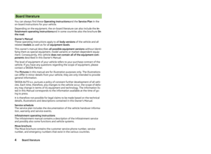 7
7 8
8 9
9 10
10 11
11 12
12 13
13 14
14 15
15 16
16 17
17 18
18 19
19 20
20 21
21 22
22 23
23 24
24 25
25 26
26 27
27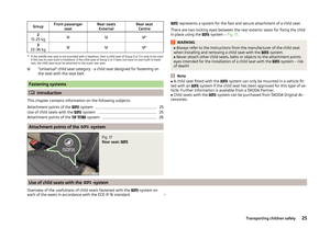 28
28 29
29 30
30 31
31 32
32 33
33 34
34 35
35 36
36 37
37 38
38 39
39 40
40 41
41 42
42 43
43 44
44 45
45 46
46 47
47 48
48 49
49 50
50 51
51 52
52 53
53 54
54 55
55 56
56 57
57 58
58 59
59 60
60 61
61 62
62 63
63 64
64 65
65 66
66 67
67 68
68 69
69 70
70 71
71 72
72 73
73 74
74 75
75 76
76 77
77 78
78 79
79 80
80 81
81 82
82 83
83 84
84 85
85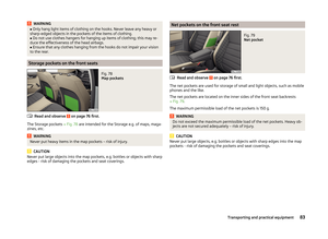 86
86 87
87 88
88 89
89 90
90 91
91 92
92 93
93 94
94 95
95 96
96 97
97 98
98 99
99 100
100 101
101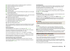 102
102 103
103 104
104 105
105 106
106 107
107 108
108 109
109 110
110 111
111 112
112 113
113 114
114 115
115 116
116 117
117 118
118 119
119 120
120 121
121 122
122 123
123 124
124 125
125 126
126 127
127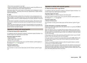 128
128 129
129 130
130 131
131 132
132 133
133 134
134 135
135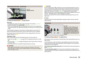 136
136 137
137 138
138 139
139 140
140 141
141 142
142 143
143 144
144 145
145 146
146 147
147 148
148 149
149 150
150 151
151 152
152 153
153 154
154 155
155 156
156 157
157 158
158 159
159 160
160 161
161 162
162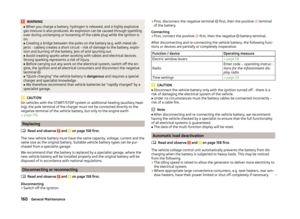 163
163 164
164 165
165 166
166 167
167 168
168 169
169 170
170 171
171 172
172 173
173 174
174 175
175 176
176 177
177 178
178 179
179 180
180 181
181 182
182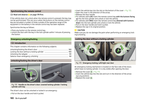 183
183 184
184 185
185 186
186 187
187 188
188 189
189 190
190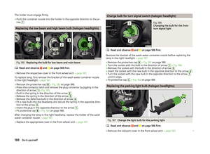 191
191 192
192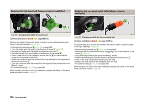 193
193 194
194 195
195 196
196 197
197 198
198 199
199 200
200 201
201 202
202 203
203 204
204 205
205 206
206 207
207 208
208 209
209 210
210 211
211 212
212 213
213 214
214 215
215