Page 177 of 216

WARNING■The sealant is hazardous to heath. Remove immediately if it comes into
contact with the skin.■
Observe the manufacturer's usage instructions for the breakdown kit.
For the sake of the environment
Used sealant or sealant whose expiry date has passed must be disposed of in
accordance with environmental protection regulations.
Note
■ A new bottle of sealant can be purchased from ŠKODA Original Parts.■Immediately replace the wheel that was repaired using the breakdown kit or
consult a specialist garage about repair possibilities.
Components of the puncture repair kit
Fig. 165
Principle sketch: Repair kit components
Read and observe
on page 174 first.
Components of the set » Fig. 165
Sticker with “max. 80 km/h”/“max. 50 mph” speed designation
Valve remover
Inflation hose with plug
Air compressor
Button for releasing the tyre pressure
12 volt cable connector
123456Tyre inflation hose
Tyre pressure indicator
ON and OFF switch
Tyre inflator bottle with sealant
Replacement valve core
The valve remover 2
has a slot at its lower end which fits into the valve core.
The kit is located in a box under the floor covering in the luggage compart-
ment. It contains a sealant and an air compressor.
Note
The declaration of conformity is included with the air compressor or the log
folder.
General information
Read and observe
on page 174 first.
For your own safety and the safety of your passengers, the following instruc-
tions must be observed before carrying out a wheel repair on the road.
Switch on the hazard warning lights system.
The warning triangle must be set up at the prescribed distance - observe
the national legal provisions when doing so.
Park the vehicle as far away as possible from the flow of traffic.
Choose a location with a flat, solid surface.
Have all the passengers get out. The passengers should not stand on the
road (instead they should remain behind a crash barrier, for instance) while
the wheel is being changed.
The national legal requirements must be observed when repairing a tyre.
The breakdown kit must not be used under the following circumstances. › The rim is damaged.
› The outside temperature is below -20 ° C.
› The cut or puncture is larger than 4 mm.
› The tyre wall is damaged.
› The result will be to drive with very low tyre pressure or with a completely
flat tyres.
› After the expiration date (see inflation bottle).
7891011174Do-it-yourself
Page 178 of 216

Preparations for using the breakdown kitRead and observe
on page 174 first.
The following preparatory work must be carried out before using the break-
down kit.
›
Switch off the engine.
›
Engage the first gear or place the selector lever of the automatic transmis-
sion in the P-position.
›
Apply the handbrake firmly.
›
Check that you can carry out the repairs with the breakdown kit » page 174,
General information .
›
Uncouple trailer, if attached.
›
Remove the breakdown kit from the boot.
›
Stick the corresponding sticker
1
» Fig. 165 on page 174 on the dashboard in
the driver's field of view.
›
Unscrew the valve cap.
›
Use the valve remover
2
to unscrew the valve core and place it on a clean
surface (rag, paper, etc.).
Sealing and inflating the tyre
Read and observe
on page 174 first.
Sealing
›
Shake the tyre inflator bottle
10
» Fig. 165 on page 174 vigorously several
times.
›
Firmly screw the inflation hose
3
onto the tyre inflator bottle
10
in a clock-
wise direction. The film on the cap is pierced automatically.
›
Remove the plug from the inflation hose
3
and push the open end fully on-
to the tyre valve.
›
Hold the bottle
10
with the bottom facing upwards and fill all of the sealing
agent from the tyre inflator bottle into the tyre.
›
Remove the empty tyre inflator bottle from the valve.
›
Screw the valve core back into the tyre valve using the valve remover
2
.
Inflating
›
Screw the air compressor tyre inflation hose
7
» Fig. 165 on page 174 firmly
onto the tyre valve.
›
Start the engine and run it in idle.
›
Plug the connector
6
into 12 Volt socket » page 79.
›
Switch on the air compressor with the ON and OFF switch
9
.
›Allow the air compressor to run until a pressure of 2.0 - 2.5 bar is achieved.
Maximum run time of 8 minutes » .›
Switch off the air compressor.
›
If you cannot reach an air pressure of 2.0 – 2.5 bar, unscrew the tyre inflation
hose
7
from the tyre valve.
›
Drive the vehicle 10 metres forwards or backwards to allow the sealing agent
to “distribute” in the tyre.
›
Firmly screw the tyre inflation hose
7
back onto the tyre valve and repeat
the inflation process.
›
If you still cannot reach the required tyre inflation pressure, this means the
tyre has sustained too much damage. You cannot seal with tyre with the
breakdown kit »
.
›
Switch off the air compressor.
›
Remove the tyre inflation hose
7
from the tyre valve.
Once a tyre pressure of 2.0 – 2.5 bar is reached, the journey may be continued
at a maximum speed of 80 km/h (50 mph).
WARNING■ If you cannot inflate the tyre to at least 2.0 bar, this means the damage
sustained was too serious. The sealing agent cannot be used to seal the
tyre.
Do not drive the vehicle! Seek help from a specialist garage.■
The tyre inflation hose and air compressor may get hot while the tyre is
being inflated – there is a risk of injury.
CAUTION
Switch off the air compressor after running 8 minutes at the most – risk of
overheating. Allow the air compressor to cool a few minutes before switching
it on again.
Notes for driving with tyre repaired
Read and observe
on page 174 first.
The filling pressure of the repaired tyre is a 10-minute test drive.
If the tyre pressure is 1.3 bar or less
›
Do not drive the vehicle! You cannot properly seal with tyre with the
breakdown kit.
If the tyre pressure is 1.3 bar or more
›
Correct the tyre pressure back to the correct value.
175Emergency equipment, and self-help
Page 179 of 216
.WARNING■ A tyre filled with sealant has the same driving characteristics as a stand-
ard tyre.�")
›Continue driving carefully to the nearest specialist garage at a maximum
speed of 80 km/h (50 mph).WARNING■ A tyre filled with sealant has the same driving characteristics as a stand-
ard tyre.■
Do not drive faster than 80 km/h (50 mph).
■
Avoid accelerating at full throttle, sharp braking and fast cornering.
Jump-starting
Introduction
This chapter contains information on the following subjects:
Jump-starting using the battery from another vehicle
176
The battery of another vehicle can be used to jump-start your vehicle if the en-
gine will not start because the battery is flat.
WARNING■ Pay attention to the warning instructions relating to working in the en-
gine compartment » page 150.■
A discharged vehicle battery can freeze at temperatures just below 0 °C.
If the battery is frozen, do not jump start with the battery of another vehi-
cle – risk of explosion.
■
Keep any sources of ignition (naked flame, smouldering cigarettes, etc.)
away from the battery – risk of explosion!
■
Never jump-start vehicle batteries with an electrolyte level that is too low
– risk of explosion and caustic burns.
■
The vent screws of the battery cells must be tightened firmly.
Note
We recommend you buy jump-start cables from a car battery specialist.Jump-starting using the battery from another vehicleFig. 166
Jump-starting: A – flat battery, B
– battery providing current
Fig. 167
Engine earth: START-STOP sys-
tem
Read and observe on page 176 first.
The starting process using the battery of another vehicle requires the use of
jumper cables.
The jump-start cables must be attached in the following sequence.
›
Attach clamp
1
to the positive terminal of the discharged battery
A
» Fig. 166 .
›
Attach clamp
2
to the positive terminal of the battery supplying power
B
.
›
Attach clamp
3
to the negative terminal of the battery supplying power
B
.
›
Attach the clamp
4
to a solid metal component firmly connected to the en-
gine block or to the engine block itself.
The jump-start cable must only be connected to the engine earthing point on
vehicles with the START-STOP system » Fig. 167.
Starting engine
›
Start the engine on the vehicle providing the power and allow it to idle.
›
Start the engine of the vehicle with the discharged battery.
176Do-it-yourself
Page 180 of 216

›If the engine does not start, halt the attempt to start the engine after 10 sec-
onds and wait for 30 seconds before repeating the process.›
Detach the jumper cables in the exact reverse order that they were attached.
Both batteries must have a rated voltage of 12 V. The capacity (Ah) of the bat-
tery supplying the power must not be significantly less than the capacity of
the discharged battery in your vehicle.
Jump-start cables
Only use jump-start cables which have an adequately large cross-section and
insulated terminal clamps. Obey the instructions of the jump start cable manu-
facturer.
Positive cable - colour coding in the majority of cases is red.
Negative cable - colour coding in the majority of cases is black.
WARNING■
Do not clamp the jump-start cable to the negative terminal of the dis-
charged battery. There is the risk of detonating gas seeping out the battery
being ignited by the strong spark which results from the engine being star-
ted.■
The non-insulated parts of the terminal clamps must never touch each
other – risk of short circuit.
■
The jump-start cable connected to the positive terminal of the battery
must not come into contact with electrically conducting parts of the vehicle
– risk of short circuit.
■
Route the jump-start cables so that they cannot be caught by any rotat-
ing parts in the engine compartment.
■
There must not be any contact between the two vehicles otherwise cur-
rent may flow as soon as the negative terminals are connected.
Towing the vehicle
Introduction
Fig. 168
Braided tow ropes/spiral tow rope
This chapter contains information on the following subjects:
Front towing eye
178
Rear towing eye
179
Vehicles with a tow hitch
179
A braided tow rope must be used for towing » Fig. 168 -
.
The following guidelines must be observed when towing.
Vehicles with manual transmission may be towed with a tow bar or a tow rope
or with the front or rear wheels raised.
Vehicles with automatic transmission may be towed with a tow bar or a tow
rope or with the front wheels raised. If the vehicle is raised at rear, the auto-
matic gearbox is damaged!
Driver of the tow vehicle
›
Engage the clutch gently when starting off or depress the accelerator partic-
ularly gently if the vehicle is fitted with an automatic gearbox.
›
Only then, approach correctly when the rope is taut.
The maximum towing speed is 50 km/h.
Driver of the towed vehicle
›
Switch on the ignition so that the steering wheel is not locked and so that
the turn signal lights, windscreen wipers and windscreen washer system can
be used.
177Emergency equipment, and self-help
Page 181 of 216

›Take the vehicle out of gear or move the selector lever into position
N if the
vehicle is fitted with an automatic gearbox.
Please note that the brake servo unit and power steering only operate if the
engine is running. If the engine is not running, significantly more physical force
is required to depress the brake pedal and steer the vehicle.
If using a tow rope, ensure that it is always kept taught.
Both drivers should be familiar with the potential issues of towing a vehicle.
Unskilled drivers should not attempt to tow another vehicle or to be towed.
The vehicle must be transported on a special breakdown vehicle or trailer if it
is not possible to tow the vehicle in the way described or if the towing dis-
tance is greater than 50 km.WARNING■ When towing, respect the national legal provisions, especially those
which relate to the identification of the towing vehicle and the vehicle be-
ing towed.■
Exercise increased caution when towing.
■
Spiral tow ropes must not be used for towing » Fig. 168 -
, the towing
eye may unscrew out of the vehicle - risk of accident.
■
The tow rope should not be twisted - risk of accident.
CAUTION
■ Do not tow-start the engine – risk of damaging the engine and the catalytic
converter. The battery from another vehicle can be used as a jump-start aid
» page 176 , Jump-starting .■
If the gearbox no longer contains any oil because of a defect, your vehicle
must only be towed with the drive wheels raised clear of the ground or on a
special breakdown vehicle or trailer.
■
To protect both vehicles when tow-starting or towing, the tow rope should
be elastic. Thus one should only use plastic fibre rope or a rope made out of a
similarly elastic material.
■
There is always a risk of excessive stresses and damage resulting at the
points to which you attach the tow rope or tow bar when you attempt to tow a
vehicle which is not standing on a paved road.
■
Attach the tow rope or the tow bar to the towing eyes » page 178 or
» page 179 to the detachable ball head of the towing equipment » page 129 .
NoteWe recommend using a tow rope from ŠKODA Original Accessories available
from a ŠKODA Partner.
Front towing eye
Fig. 169
Removing the cap / installing the towing eye
Read and observe
and on page 178 first.
Removing/installing the cap
›
Press on the fuel filler flap in the direction of the arrow
1
» Fig. 169 .
›
Remove the cap in the direction of the arrow
2
.
›
After unscrewing the cap of the towing eye, insert the cap in the region of
the arrow
1
and then press the opposite side of the cap.
The cap must engage firmly.
Removing/installing the towing eye
›
Manually screw the towing eye as far as it will go in the direction of the ar-
row
3
» Fig. 169 » .
For tightening purposes, we recommend, for example, using the wheel
wrench, towing eye from another vehicle or a similar object that can be pushed through the eye.
›
Unscrew the towing eye against the direction of the arrow
3
.
WARNINGThe towing eye must always be screwed in fully and firmly tightened, oth-
erwise the towing eye can tear when towing in or tow-starting.178Do-it-yourself
Page 182 of 216

Rear towing eyeFig. 170
Rear towing eye
Read and observe and on page 178 first.
The rear towing eye is located below the rear bumper on the right » Fig. 170.
Vehicles with a tow hitch
Read and observe
and on page 178 first.
The removable towing ball may be fitted and used for towing on vehicles witha factory fitted tow hitch » page 129, Hitch .
Towing the vehicle using the towing device is a viable alternative solution to
using the towing eye.
CAUTION
The detachable ball rod and/or the vehicle can be damaged if an unsuitable
tow bar is used.
Remote control
Introduction
This chapter contains information on the following subjects:
Replacing the battery in the remote control key
179
Synchronising the remote control
180CAUTION■ The replacement battery must have the same specification as the original
battery.■
We recommend having faulty rechargeable batteries replaced by a ŠKODA
service partner.
■
Pay attention to the correct polarity when changing the battery.
For the sake of the environment
Dispose of the used battery in accordance with national legal provisions.
Replacing the battery in the remote control key
Fig. 171
Remove cover/take out battery
Read and observe
on page 179 first.
The battery change is carried out as follows.
›
Flip out the key.
›
Press off the battery cover
A
» Fig. 171 with your thumb or by using a flat
screwdriver in region
B
.
›
Open the battery in the direction of the arrow
1
.
›
Remove the discharged battery in the direction of arrow
2.›
Insert the new battery.
›
Insert the battery cover
A
and press it down until it clicks audibly into place.
The key has to be synchronised if the vehicle cannot be unlocked or locked
with the remote control key after replacing the battery » page 180.
Note
Replacing the battery in the key a glued decorative cover requires the cover to
be destroyed. A replacement cover can be purchased from a ŠKODA Partner.179Emergency equipment, and self-help
Page 183 of 216

Synchronising the remote controlRead and observe
on page 179 first.
If the vehicle does not unlock when the remote control is pressed, the key maynot be synchronised. This can occur when the buttons on the remote control
key are actuated a number of times outside of the operative range of the
equipment or the battery in the remote control key has been replaced.
Synchronise the key as follows.
›
Press any button on the remote control key.
›
Unlock the door with the key in the lock cylinder within 1 minute of pressing the button.
Emergency unlocking/locking
Introduction
This chapter contains information on the following subjects:
Unlocking/locking the driver's door
180
Locking the door without a locking cylinder
180
Unlocking the tailgate
181
Selector lever-emergency unlocking
181
Unlocking/locking the driver's door
Fig. 172
Handle on the driver's door: covered locking cylinder / locking
cylinder with key
The driver's door can be unlocked or locked in an emergency.
›
Pull on the door handle and hold it pulled.
› Insert the vehicle key into the slot on the bottom of the cover
» Fig. 172.›Open the cover in the direction of the arrow.›
Release the door handle.
›
For vehicles with LHD insert the remote control key with the buttons facing
up into the lock cylinder and unlock or lock the vehicle.
›
For vehicles with RHD insert the remote control key directed with buttons
down into the lock cylinder and unlock or lock the vehicle.
›
Pull on the door handle and hold it pulled.
›
Replace the cap in its original position.
CAUTION
Make sure you do not damage the paint when performing an emergency lock-
ing/unlocking.
Locking the door without a locking cylinder
Fig. 173
Emergency locking: Left/right rear door
An emergency locking mechanism is located on the face side of the doors
which have no locking cylinder. It is only visible after opening the door.
›
Remove the cover
A
» Fig. 173 .
›
Insert the vehicle key into the slot and turn in the direction of the arrow
(sprung position).
›
Replace the cover
A
.
180Do-it-yourself
Page 184 of 216

Unlocking the tailgateFig. 174
Emergency unlocking of the boot
lid
The boot lid can be unlocked manually in an emergency.
›
Insert a screwdriver or similar tool into the opening in the trim » Fig. 174 as
far as the stop.
›
Unlock the lid by moving it in the direction of the arrow.
›
Open the tailgate.
Selector lever-emergency unlocking
Fig. 175
Selector lever-emergency unlocking
›
Firmly apply the handbrake.
›
Insert a flathead screwdriver into the gap in the arrow range
1
» Fig. 175
and carefully lift the cover in arrow direction
2
.
›
Likewise lift the cover with your hand as well.
›
With one finger, push the yellow plastic element in the direction of arrow
3
down to the stop.
›
At the same time, press the locking button in the selector lever and move the selector lever to N.
The selector lever will be locked once more if it is moved again to P.
Replacing windscreen wiper blades
Introduction
This chapter contains information on the following subjects:
Replacing the windscreen wiper blades
181
Replacing the rear window wiper blade
182WARNINGReplace the windscreen wiper blades once or twice a year for safety rea-
sons. These can be purchased from a ŠKODA Partner.
Replacing the windscreen wiper blades
Fig. 176
Windscreen wiper blade
Read and observe
on page 181 first.
Adjust the windscreen wiper arms to the service position before replacing the
windscreen wiper blades.
Adjusting service position for changing wiper blades
›
Close the bonnet.
›
Switch the ignition off and on again.
›
Push the windscreen wiper lever to position
4
within 10 seconds » page 68,
Windscreen wipers and washers .
›
Hold the lever in this position for about 2 seconds.
Move the windscreen wiper arms into the service position.
Removing the wiper blade
›
Lift the wiper arm from the window in the direction of arrow
1
» Fig. 176 .
181Emergency equipment, and self-help
 1
1 2
2 3
3 4
4 5
5 6
6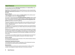 7
7 8
8 9
9 10
10 11
11 12
12 13
13 14
14 15
15 16
16 17
17 18
18 19
19 20
20 21
21 22
22 23
23 24
24 25
25 26
26 27
27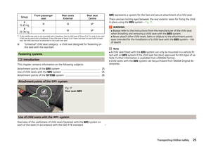 28
28 29
29 30
30 31
31 32
32 33
33 34
34 35
35 36
36 37
37 38
38 39
39 40
40 41
41 42
42 43
43 44
44 45
45 46
46 47
47 48
48 49
49 50
50 51
51 52
52 53
53 54
54 55
55 56
56 57
57 58
58 59
59 60
60 61
61 62
62 63
63 64
64 65
65 66
66 67
67 68
68 69
69 70
70 71
71 72
72 73
73 74
74 75
75 76
76 77
77 78
78 79
79 80
80 81
81 82
82 83
83 84
84 85
85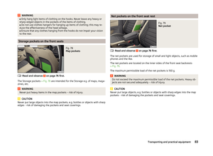 86
86 87
87 88
88 89
89 90
90 91
91 92
92 93
93 94
94 95
95 96
96 97
97 98
98 99
99 100
100 101
101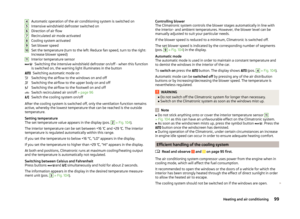 102
102 103
103 104
104 105
105 106
106 107
107 108
108 109
109 110
110 111
111 112
112 113
113 114
114 115
115 116
116 117
117 118
118 119
119 120
120 121
121 122
122 123
123 124
124 125
125 126
126 127
127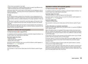 128
128 129
129 130
130 131
131 132
132 133
133 134
134 135
135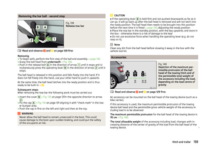 136
136 137
137 138
138 139
139 140
140 141
141 142
142 143
143 144
144 145
145 146
146 147
147 148
148 149
149 150
150 151
151 152
152 153
153 154
154 155
155 156
156 157
157 158
158 159
159 160
160 161
161 162
162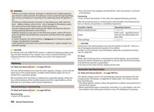 163
163 164
164 165
165 166
166 167
167 168
168 169
169 170
170 171
171 172
172 173
173 174
174 175
175 176
176 177
177 178
178 179
179 180
180 181
181 182
182 183
183 184
184 185
185 186
186 187
187 188
188 189
189 190
190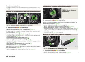 191
191 192
192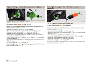 193
193 194
194 195
195 196
196 197
197 198
198 199
199 200
200 201
201 202
202 203
203 204
204 205
205 206
206 207
207 208
208 209
209 210
210 211
211 212
212 213
213 214
214 215
215