Page 185 of 216

›Fold the wiper blade out to the stop in the same direction.›Hold the upper part of the wiper arm and press the securing mechanism A
in the direction of arrow
2
.
›
Remove the wiper blade in the direction of the arrow
3
.
Fitting the wiper blade
›
Push the wiper blade in the opposite direction of the arrow
3
as far as the
stop.
›
Check that the wiper blade is correctly attached.
›
Fold the wiper arm back to the windscreen.
›
Turn on the ignition and press the lever into position
4
» page 68 , Wind-
screen wipers and washers .
Move the windscreen wiper arms into the home position.
Replacing the rear window wiper blade
Fig. 177
Rear window wiper blade
Read and observe
on page 181 first.
Removing the wiper blade
›
Lift the wiper arm from the window in the direction of the arrow
1
» Fig. 177 .
›
Tilt the wiper blade to the stop in the same direction.
›
Hold the upper part of the wiper arm and press the securing mechanism
A
in the direction of arrow
2
.
›
Remove the wiper blade in the direction of the arrow
3
.
Fitting the wiper blade
›
Push the wiper blade in the opposite direction of the arrow
3
until it locks
into place.
›
Check that the wiper blade is correctly attached.
›
Fold the wiper arm back to the windscreen.
Fuses and light bulbs
Fuses
Introduction
This chapter contains information on the following subjects:
Fuses in the dash panel
183
Assignment of the fuses in the dash panel
183
Fuses in the engine compartment
185
Fuse cover / fuse assignment in the engine compartment
185
Individual electrical circuits are protected by fuses.
Switch off the ignition and the corresponding power consuming device before
replacing a fuse.
Find out which fuse belongs to the component that is not operating
» page 183 , Fuses in the dash panel or » page 185 , Fuses in the engine com-
partment .
Fuse colourMaximum amperagelight brown5dark brown7.5red10blue15yellow/blue20white25green/pink30green40red50WARNINGAlways read and observe the warnings before completing any work in the
engine compartment » page 150. 182Do-it-yourself
Page 186 of 216

CAUTION■“Never repair” fuses or replace them with a fuse of a higher amperage – risk
of fire. This may also cause damage at another part of the electrical system.■
A blown fuse is recognisable by the molten metal strip. Replace the faulty
fuse with a new one of the same amperage.
■
If a new fuse burns through again, consult a specialist immediately.
Note
■
We recommend that you always carry replacement fuses in the vehicle. A box
of replacement fuses can be purchased from ŠKODA Original Accessories.■
One fuse may cover several consumers.
■
A single consumer may use several fuses.
Fuses in the dash panel
Fig. 178
Remove the cover
Read and observe and on page 182 first.
The fuses are located on the bottom of the dash panel behind a cover.
Replacing fuses
›
Remove the cover of the fuse box » Fig. 178 in the direction of the arrow.
›
Remove the plastic clip from the holder in the fuse box cover in the dash
panel.
›
Place the clamp on the respective fuse and pull this fuse out.
›
Insert a new fuse.
›
Replace the clamp in the original place.
›
Insert the top edge of the cover into the dash panel first.
›
Push the lower edge of the cover in the region
A
.
Assignment of the fuses in the dash panelFig. 179
Schematic representation of the fuse box for vehicles with left-
hand steering/right-hand steering
Read and observe
and on page 182 first.
No.Power consumer1Left parking light, parking light, high-mounted brake light2Central locking system3Relay for ignition4Right-hand light, rear fog light, license plate light5Power windows - driver6Central control unit, interior lighting7Horn8Towing hitch - left light
9
Operating lever beneath the steering wheel, engine control unit (on-
ly without KESSY), automatic gearbox (only without KESSY), selector
lever of the automatic gearbox (only without KESSY), ESC (only with-
out KESSY), control unit for trailer detection (only without KESSY),
power steering (only without KESSY), airbag (only without KESSY)10Power windows - rear left11Headlight cleaning system12Radio display1312-volt socket in luggage compartment14Operating lever under the steering wheel, light switch, ignition key
removal lock (automatic gearbox), diagnostic connector, headlight
flasher, SmartGate controller, rain sensor, light sensor 183Fuses and light bulbs
Page 187 of 216

No.Power consumer15Control unit for air conditioning system, selector lever of the auto-
matic gearbox16Instrument cluster17Alarm system, horn18Not assigned19Not assigned20Not assigned21Not assigned22Front- and rear windscreen wiper system23Not assigned24Blower fan for air conditioning system, heating, control unit for air
conditioning, heating25Not assigned26Heated front seats27Rear window wiper28Not assigned29Airbag (only with KESSY)
30
Power windows, light switches, reverse light switches, control unit
for air conditioning system, control unit for park assist, exterior mir-
ror, power feed for center button strip, power feed for side button
strip, interior mirror31Fuel pump, control unit for radiator fan, cruise control, coil of the re-
lay for the front and rear windscreen wipers32Diagnostic connector, headlight range adjustment33Coil on starter relay, clutch pedal switch34Heated windscreen washer jets35Not assigned36Heated front seats37Radar38Not assigned39Electrical auxiliary heating system40Not assigned41Rear window heaterNo.Power consumer42Power windows - front passenger43Towing hitch - contact in the socket44Cigarette lighter, 12-volt power socket45Power windows - rear right46Front and rear window washer, operating lever under the steering
wheel47Towing hitch - contact in the socket48Towing hitch - right light49Control unit for fuel pump50Radio51Heating of the external mirror52KESSY control unit53KESSY steering lock54Not assigned55Heated front seats56Not assigned57Not assigned58Not assigned59Not assigned184Do-it-yourself
Page 188 of 216

Fuses in the engine compartmentFig. 180
Remove the cover
Read and observe
and on page 182 first.
Replacing fuses
›
Press the lock button on the cover in direction of arrow
1
» Fig. 180 .
›
Remove the cover in the direction of the arrow
2
.
›
Remove the plastic clip from the holder in the fuse box cover in the dash
panel.
›
Replace the appropriate fuse.
›
Replace the clamp in the original position.
›
Place the cover on top of the fuse box.
›
Push in the locking button on the cover and lock.
The cover must engage securely.
Fuse cover / fuse assignment in the engine compartment
Fig. 181
Fitting and removing fuses / fuses
Read and observe and on page 182 first.
Fitting and removing fuse cover
›
Release the cover of the fuses in the direction of arrow
1
» Fig. 181 with the
screwdriver in the tool kit » page 168.
›
Remove the cap in the direction of the arrow
2
.
›
After the fuse has been replaced, replace the cap in the opposite direction to
the arrow
2
.
The cap must engage firmly.
No.Power consumer1Radiator fan2Control unit for glow plug system3Control unit for ABS/ESC4Electrical auxiliary heating system5Electrical auxiliary heating system6Automatic gearbox7Engine control unit8Windscreen wipers9Central control unit10Control unit for ABS/ESC11Not assigned12Engine components13Brake pedal switch14Engine components, coil of the fuel pump relay15Engine control unit16Starter17Engine control unit18Engine components, coils of the relay for auxiliary electric heater, radi-
ator fan19Lambda probe20Engine components, control unit for glow plug system, heating the
crankcase ventilation185Fuses and light bulbs
Page 189 of 216

Replacing bulbs
Introduction
This chapter contains information on the following subjects:
Bulb arrangement in the headlights
186
Removing and installing the cover in the front wheel arch
187
Fitting and removing the wash water container nozzle
187
Replacing the low beam and high beam bulb (halogen headlights)
188
Change bulb for turn signal switch (halogen headlight)
188
Replacing the parking light bulb (halogen headlights)
188
Changing bulb for daytime running lights switch (halogen headlight)
189
Replacing the high beam bulb (halogen projector headlights)
189
Replacing the high beam bulb (halogen projector headlights)
190
Replacing the turn signal switch bulb (halogen projector headlights)
190
Replacing the bulb for the fog light
191
Changing the licence plate light bulb
191
Rear Light
192
Replacing bulbs in rear light
192
Some manual skills are required to change a bulb. For this reason, if uncertain,
we recommend that bulbs are replaced by a specialist garage or other expert
help is sought.
› Switch off the ignition and all of the lights before replacing a bulb.
› Faulty bulbs must only be replaced with the same type of bulbs. The designa-
tion is located on the light socket or the glass bulb.
› A stowage compartment for replacement bulbs is located in a plastic box in
the spare wheel or underneath the floor covering in the boot.
WARNING■ Always read and observe the warnings before completing any work in the
engine compartment » page 150.■
Accidents can be caused if the road in front of the vehicle is not suffi-
ciently illuminated and the vehicle cannot or can only be seen with difficul-
ty by other road users.
■
Bulbs H8, H7 and H4 are pressurised and may burst when changed - there
is a risk of injury! We therefore recommended wearing gloves and safety
glasses when changing a bulb.
■
Switch off the respective vehicle light when changing the bulb.
CAUTIONDo not take hold of the glass bulb with naked fingers (even the smallest
amount of dirt reduces the working life of the light bulb). Use a clean cloth,
napkin, or similar.
Note
■ This Owner's Manual only describes the replacement of bulbs where it is pos-
sible to replace the bulbs on your own without any complications arising. Other
light bulbs should be changed by your specialist garage.■
We recommend that you always carry a box of replacement bulbs in the vehi-
cle. Replacement bulbs can be purchased from ŠKODAOriginal Accessories.
■
We recommend having the headlight settings checked by a specialist garage
after replacing a bulb in the main beam, low beam or fog lights.
■
Visit a specialist garage if an LED is faulty.
Bulb arrangement in the headlights
Fig. 182
Principle sketch: Halogen headlights/halogen projector head-
lights
Read and observe
and on page 186 first.
The vehicle is equipped with headlights with halogen bulbs.
Bulb arrangement » Fig. 182
Dayl. dri. light
Low beam, high beam and parking light
Flashing
Low beam
High beam and turning signal switch
ABCDE186Do-it-yourself
Page 190 of 216

Removing and installing the cover in the front wheel archFig. 183
Remove the plastic cover
Read and observe and on page 186 first.
The cover in the front wheel must be removed in order to change certain light
bulbs.
Details about removing the cover - if needed - are given in the description of
each lamp change.
Removing
›
Adjust front wheels in the direction of center of the vehicle.
›
Insert the clamp for removing the full wheel covers » page 168, Vehicle tool
kit into the recess in the cover.
›
Remove the cover by pulling the hook in the direction of arrow » Fig. 183.
Fitting
›
Insert and push the cover into the corresponding opening.
The cover must engage securely.
Fitting and removing the wash water container nozzleFig. 184
Remove the holder of the wash water container nozzle
Read and observe
and on page 186 first.
The holder of the wash water container nozzle must be removed in order to
replace some light bulbs. The holder is located in the engine compartment,
front right.
Details about removing the holder - if needed - are given in each lamp replace-
ment description .
Removing
›
Unclip the container nozzle
A
from the holder in the direction of arrow
1
» Fig. 184 .
›
Insert a finger into the recess
B
in the direction of arrow
2
and lift the catch
C
in the direction of arrow
3
.
›
Remove the holder of the container nozzle in the direction of arrow
4
.
Fitting
›
Slide the holder of the container nozzle in the opposite direction to the ar-
row
4
» Fig. 184 .
187Fuses and light bulbs
Page 191 of 216

Fig. 185
Repla")
The holder must engage firmly.›
Push the container nozzle into the holder in the opposite direction to the ar-
row
1
.
Replacing the low beam and high beam bulb (halogen headlights)
Fig. 185
Replacing the bulb for low beam and main beam
Read and observe
and on page 186 first.
›
Remove the respective cover in the front wheel arch » page 187.
To replace lamp, first remove the bracket of the wash water container nozzle
in the right headlight » page 187.
›
Remove the protective cap
B
» Fig. 182 on page 186 .
›
Press the connector latch and remove the plug connector by jiggling in the
direction of arrow
1
» Fig. 185 .
›
Push in the spring in the direction of the arrow
2›
Release the spring in the direction of the arrow
3
.
›
Remove the defective bulb in the direction of arrow
4
.
›
Fit a new bulb into the headlamp and secure the spring in the opposite direc-
tion to the arrow
3
.
›
Insert the plug in the opposite direction to the arrow
1
.
›
Fit protective cap
B
» Fig. 182 on page 186 .
After changing the lamp in the right headlamp, replace the holder of the wash
water container nozzle » page 187.
›
Replace the appropriate cover in the front wheel arch » page 187.
Change bulb for turn signal switch (halogen headlight)Fig. 186
Changing the bulb for the front
turn signal light
Read and observe and on page 186 first.
Remove the bracket of the wash water container nozzle before replacing the
lamp in the right headlight » page 187.
›
Remove the protective cap
B
» Fig. 182 on page 186 .
›
Turn the socket with the bulb in the direction of arrow
1
» Fig. 186 .
›
Remove the socket with the bulb in the direction of arrow
2
.
›
Insert the socket with the new bulb in the opposite direction to the arrow
2
.
›
Turn the socket with the new bulb in the opposite direction to the arrow
1
until it stops.
›
Fit protective cap
C
» Fig. 182 on page 186 .
Replacing the parking light bulb (halogen headlights)
Fig. 187
Change the light bulb for the parking light
Read and observe
and on page 186 first.
›
Remove the relevant cover in the front wheel arch » page 187.
188Do-it-yourself
Page 192 of 216

Remove the holder of the wash water container nozzle before replacing the
lamp in the right headlight » page 187.›
Remove the protective cap
B
» Fig. 182 on page 186 .
›
Remove the bulb holder with the bulb by jiggling it out in the direction of the
arrow
1
» Fig. 187 .
›
Grasp the lamp socket at the places marked by arrows.
›
Remove the faulty bulb from the holder in the direction of the arrow
2
.
›
Push a new bulb into the bulb holder up to the stop.
›
Replace the bulb holder with the bulb in the headlamp.
›
Fit protective cap
B
» Fig. 182 on page 186 .
After changing the lamp in the right headlamp, replace the holder of the wash
water container nozzle » page 187.
›
Replace the appropriate cover in the front wheel arch » page 187.
Changing bulb for daytime running lights switch (halogen
headlight)
Fig. 188
Changing the bulb for the day-
time running light
Read and observe and on page 186 first.
›
Remove the relevant cover in the front wheel arch » page 187.
›
Turn the socket with the bulb in the direction of arrow
1
» Fig. 188 .
›
Remove the socket with the bulb in the direction of arrow
2
.
›
Chenge the bulb in the socket.
›
Insert the socket with the new bulb into the headlight in the opposite direc-
tion to the arrow
2
.
›
Turn the socket with the new bulb in the opposite direction to the arrow
1
until it stops.
›
Replace the appropriate cover in the front wheel arch » page 187.
Replacing the high beam bulb (halogen projector headlights)Fig. 189
Changing the bulb for the low beam
Read and observe
and on page 186 first.
›
Remove the relevant cover in the front wheel arch » page 187.
›
Remove the protective cap
D
» Fig. 182 on page 186 .
›
Turn the holder with the bulb in the direction of arrow
1
» Fig. 189 .
›
Remove the holder with the bulb in the direction of arrow
2
.
›
Remove the bulb from the holder in the direction of the arrow
3
.
›
Insert a new bulb into the connector so that the lug
A
on the connector
snaps into the groove on the bulb.
›
Insert the connector with the new bulb into the headlight in the opposite di-
rection to the arrow
2
.
›
Turn the connector with the new bulb in the opposite direction to the arrow
1
until it stops.
›
Fit protective cap
D
» Fig. 182 on page 186 .
›
Replace the appropriate cover in the front wheel arch » page 187.
189Fuses and light bulbs
 1
1 2
2 3
3 4
4 5
5 6
6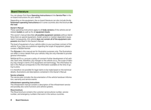 7
7 8
8 9
9 10
10 11
11 12
12 13
13 14
14 15
15 16
16 17
17 18
18 19
19 20
20 21
21 22
22 23
23 24
24 25
25 26
26 27
27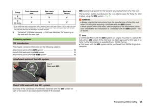 28
28 29
29 30
30 31
31 32
32 33
33 34
34 35
35 36
36 37
37 38
38 39
39 40
40 41
41 42
42 43
43 44
44 45
45 46
46 47
47 48
48 49
49 50
50 51
51 52
52 53
53 54
54 55
55 56
56 57
57 58
58 59
59 60
60 61
61 62
62 63
63 64
64 65
65 66
66 67
67 68
68 69
69 70
70 71
71 72
72 73
73 74
74 75
75 76
76 77
77 78
78 79
79 80
80 81
81 82
82 83
83 84
84 85
85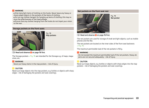 86
86 87
87 88
88 89
89 90
90 91
91 92
92 93
93 94
94 95
95 96
96 97
97 98
98 99
99 100
100 101
101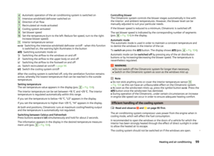 102
102 103
103 104
104 105
105 106
106 107
107 108
108 109
109 110
110 111
111 112
112 113
113 114
114 115
115 116
116 117
117 118
118 119
119 120
120 121
121 122
122 123
123 124
124 125
125 126
126 127
127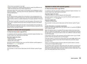 128
128 129
129 130
130 131
131 132
132 133
133 134
134 135
135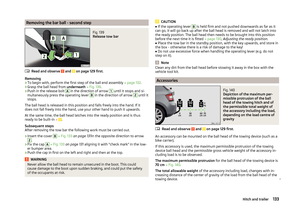 136
136 137
137 138
138 139
139 140
140 141
141 142
142 143
143 144
144 145
145 146
146 147
147 148
148 149
149 150
150 151
151 152
152 153
153 154
154 155
155 156
156 157
157 158
158 159
159 160
160 161
161 162
162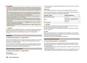 163
163 164
164 165
165 166
166 167
167 168
168 169
169 170
170 171
171 172
172 173
173 174
174 175
175 176
176 177
177 178
178 179
179 180
180 181
181 182
182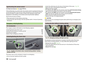 183
183 184
184 185
185 186
186 187
187 188
188 189
189 190
190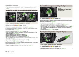 191
191 192
192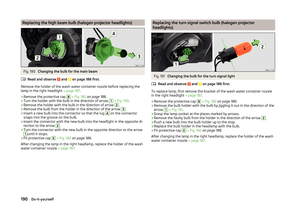 193
193 194
194 195
195 196
196 197
197 198
198 199
199 200
200 201
201 202
202 203
203 204
204 205
205 206
206 207
207 208
208 209
209 210
210 211
211 212
212 213
213 214
214 215
215