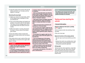
Page 33 of 284

The essentials
Level control Fuel Fig. 42
The flap that covers the tank cap is unlocked
and locked automatically using the central
locking.
Opening the fuel tank cap
●
Open the fuel tank flap by pressing on the
left side.
● Unscrew the cap by turning it to the left.
● Place it in the space on the hinge of the
open flap ››› Fig. 42 .
C lo
sing the fuel tank cap
● Unscrew the cap by turning it to the right as
far as it will go.
● Close the lid.
››› in Filling the tank on page 193
›››
page 193 Oil
Fig. 43
Fig. 44
The level is measured using the dipstick loca-
ted in the engine compartment
››› page 198
.
The oi l
should leave a mark between zones
A and
C . It should never exceed zone
A .
● Zone A : Do not add oil.
● Zone B : You can add oil but keep the level
in that zone.
● Zone C : Add oil up to zone
B .
Topping up engine oil
● Unscrew cap from oil filler opening.
● Add oil slowly.
● At the same time, check the level to ensure
you do not add too much.
● When the oil level reaches at least zone B ,
unscrew the engine oil filler cap carefully.
››› in Changing engine oil on page 202
››› page 200 31
Technical specifications
Advice
Operation
Safety
The essentials
Page 34 of 284
The essentials
Coolant Fig. 45
The coolant tank is located in the engine
compartment
›››
page 198
.
When the en gine i
s cold, replace the coolant
when the level is below .
››› in Engine coolant specifications on
page 203
››› page 203 Brake fluid
Fig. 46
The brake fluid reservoir is located in the en-
gine compartment
›››
page 198.
The level should be between the and
marks. If it is below , please visit a Techni-
cal Service.
››› in Topping up the brake fluid on
page 204
››› page 204 Windscreen washer
Fig. 47
The windscreen washer reservoir is located in
the engine compartment
›››
page 198.
To top up, mix water with a product recom-
mended by SEAT.
In cold temperatures, add anti-freeze.
››› in Checking and topping up the
windscreen washer reservoir with water
on page 205
››› page 204 32
Page 35 of 284

The essentials
Fuses Fig. 48
Fig. 49
Underneath the instrument panel
The fuse box is located behind the storage
compartment
››› Fig. 48 .
In the en gine c
ompartment
Press the locking tabs to release the fuse box
cover ››› Fig. 49
.
››› in Introduction on page 231
›››
page 231 Battery
The battery is located in the engine compart-
ment
›››
page 198. It does not require
m aint
enance. It is checked as part of the In-
spection Service.
››› in Important safety warnings for
handling a vehicle battery on page 206
››› page 205 Action in the event of a
puncture
With anti-puncture kit Fig. 50
The anti-puncture kit is located under the
floor panel in the luggage compartment.
Sealing the tyre
●
Unscrew the tyre valve cap and insert. Use
the ››› Fig. 50 1 tool to remove the insert.
Place it on a clean surface.
● Shake the tyre sealant bottle vigorously
››› Fig. 50 10 .
● Screw the inflator tube ››› Fig. 50 3 into
the sealant bottle. The bottle's seal will break
automatically. » 33
Technical specifications
Advice
Operation
Safety
The essentials
Page 36 of 284

The essentials
● Remove the lid from the filling tube
››› Fig. 50 3 and screw the open end of the
tube into the tyre valve.
● With the tyre sealant bottle upside down,
fill the tyre with the contents of the sealant
bottle.
● Remove the bottle from the valve.
● Place the insert back into the tyre valve us-
ing the tool ››› Fig. 50 1 .
Inflating the tyre
● Screw the compressor tyre inflator tube
››› Fig. 50 5 into the tyre valve.
● Check that the air bleed screw is closed
››› Fig. 50 7 .
● Start the engine and leave it running.
● Insert the connector ››› Fig. 50 9 into the
vehicle's 12-volt socket ›››
page 113.
● Turn the air compressor on with the ON/OFF
switch ››› Fig. 50 8 .
● Keep the air compressor running until it
reaches 2.0 to 2.5 bar
(29-36 psi/200-250 kPa). a maximum of 8
minutes .
● Di s
connect the air compressor.
● If it does not reach the pressure indicated,
unscrew the tyre inflator tube from the valve.
● Move the vehicle 10m so that the sealant is
distributed throughout the tyre. ●
Screw the compressor tyre inflator into the
valve.
● Repeat the inflation process.
● If the indicated pressure still cannot be
reached, the tyre is too badly damaged. Stop
and request assistance from an authorised
technician.
● Disconnect the air compressor. Unscrew
the tyre inflator tube from the tyre valve.
● When the tyre pressure is between 2.5 and
2.0 bars, continue driving without exceeding
80 km/h (50 mph).
● Check the pressure again after 10 minutes
››› page 222.
››› in TMS (Tyre Mobility System)* on
page 221
››› page 221 With spare wheel
Fig. 51
See Fig. for positioning 2 Fig. 52
Jack anchor points An adapter for the anti-theft wheel bolts*
Towline anchorage
Box spanner for wheel bolts*
Crank handle for jack
Jack*
1 2
3
4
5
34
Page 37 of 284

The essentials
Wire hook for pulling off the wheel cov-
ers*/wheel bolt cap clip.
● Take out the spare wheel and the tools that
are located under the floor panel in the lug-
gage compartment.
● Take out the wheel cover or the bolt caps.
● Loosen the bolts with the box spanner (1
turn to the left).
● Mount the jack on the support points de-
signed for this purpose on the strut
››› Fig. 52 .
● Rai
se the vehicle, turning the jack until it is
slightly lifted off the ground.
● Unscrew the bolts completely and remove
the punctured wheel.
● Put the spare wheel in place. Screw on the
bolts and tighten them loosely with the box
spanner.
● Lower the vehicle with the jack. Finish tight-
ening the bolts with the box spanner.
››› in What to do first on page 217
››› page 217 6
Emergency towing of the
vehicle
Towing Fig. 53
Fig. 54
The towline anchorages are located under
the floor panel in the luggage compartment.Switch on the ignition so that the turn sig-
nals, windscreen wipers and windscreen
washer can work. Ensure that the steering
wheel is unlocked and moves freely.
Place the gear lever in neutral on vehicles
with a manual gearbox. With an automatic
gearbox, place the lever in N.
To brake, press the brake pedal firmly. The
brake servo does not work when the engine
is switched off.
The power steering only works when the igni-
tion is switched on and the vehicle is moving,
provided that the battery is sufficiently charg-
ed. Otherwise, it will need more force.
Ensure that the tow rope remains taut at all
times.
Tow rope or tow bar
The tow bar offers increased safety and a
lower risk of damage.
The tow rope is recommended when there is
no tow bar. It must be elastic so that it does
not damage the vehicle.
Towline anchorages
Attach the bar or rope to the towline ancho-
rages.
It is located with the vehicle's tools
››› page 220
.
» 35
Technical specifications
Advice
Operation
Safety
The essentials
Page 38 of 284
The essentials
Screw the towline anchorage into the screw
connection ››› Fig. 53 o
›
›› Fig. 54 and tighten
it with the wheel brace.
››› in General information on page 225
››› page 224 36
Page 39 of 284

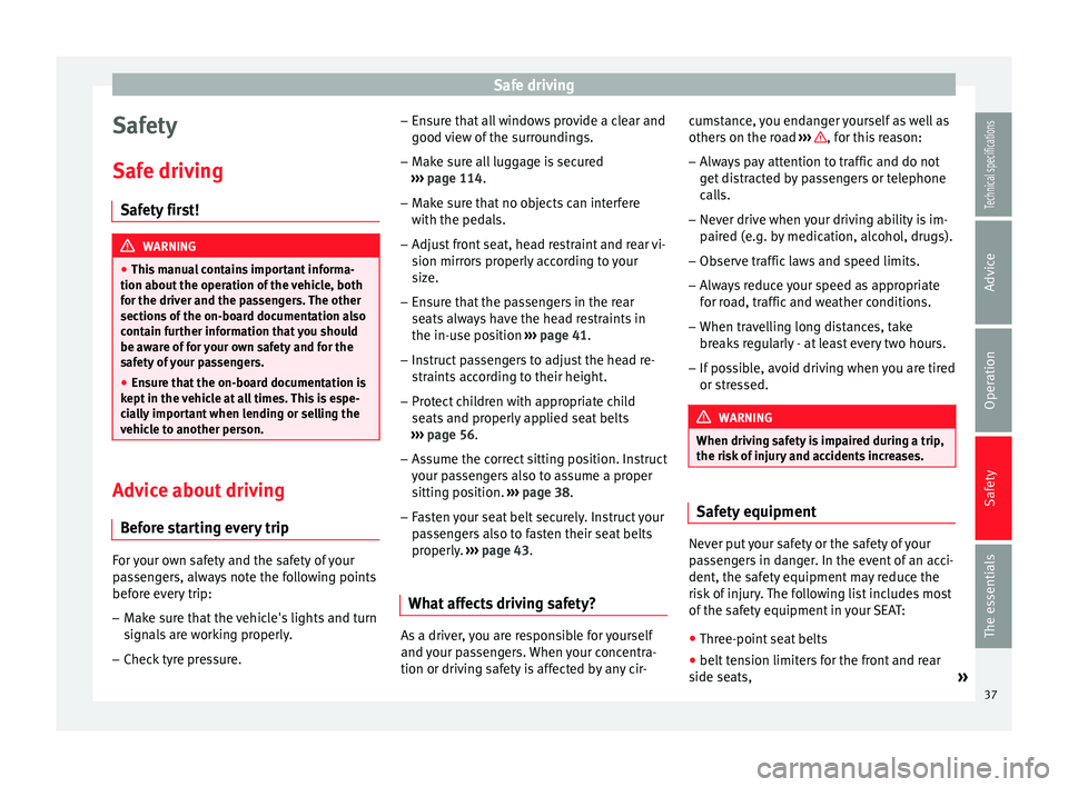
Safe driving
Safety
Safe driving Safety first! WARNING
● This manual contains important informa-
tion about the operation of the vehicle, both
for the driver and the passengers. The other
sections of the on-board documentation also
contain further information that you should
be aware of for your own safety and for the
safety of your passengers.
● Ensure that the on-board documentation is
kept in the vehicle at all times. This is espe-
cially important when lending or selling the
vehicle to another person. Advice about driving
Before starting every trip For your own safety and the safety of your
passengers, always note the following points
before every trip:
– Make sure that the vehicle's lights and turn
signals are working properly.
– Check tyre pressure. –
Ensure that all windows provide a clear and
good view of the surroundings.
– Make sure all luggage is secured
››› page 114 .
– Mak
e sure that no objects can interfere
with the pedals.
– Adjust front seat, head restraint and rear vi-
sion mirrors properly according to your
size.
– Ensure that the passengers in the rear
seats always have the head restraints in
the in-use position ››› page 41.
– Instruct passengers to adjust the head re-
straints according to their height.
– Protect children with appropriate child
seats and properly applied seat belts
››› page 56.
– Ass
ume the correct sitting position. Instruct
your passengers also to assume a proper
sitting position. ››› page 38.
– Fasten your seat belt securely. Instruct your
passengers also to fasten their seat belts
properly. ››› page 43.
What
affects driving safety? As a driver, you are responsible for yourself
and your passengers. When your concentra-
tion or driving safety is affected by any cir-cumstance, you endanger yourself as well as
others on the road
››› , for this reason:
– Always pay attention to traffic and do not
get distracted by passengers or telephone calls.
– Never drive when your driving ability is im-
paired (e.g. by medication, alcohol, drugs).
– Observe traffic laws and speed limits.
– Always reduce your speed as appropriate
for road, traffic and weather conditions.
– When travelling long distances, take
breaks regularly - at least every two hours.
– If possible, avoid driving when you are tired
or stressed. WARNING
When driving safety is impaired during a trip,
the risk of injury and accidents increases. Safety equipment
Never put your safety or the safety of your
passengers in danger. In the event of an acci-
dent, the safety equipment may reduce the
risk of injury. The following list includes most
of the safety equipment in your SEAT:
● Three-point seat belts
● belt tension limiters for the front and rear
side seats, »
37
Technical specifications
Advice
Operation
Safety
The essentials
Page 40 of 284

Safety
● Belt tensioners for the front seats
● Front airbags
● knee airbags,
● Side airbags in the front seat backrests
● Side airbags in the rear seat backrests*
● Head-protection airbags
● “ISOFIX” anchor points for child seats in
the rear side seats with the “ISOFIX” system,
● Height-adjustable front head restraints
● Rear head restraints with in-use position
and non-use position
● Adjustable steering column
The safety equipment mentioned above
works together to provide you and your pas-
sengers with the best possible protection in
the event of an accident. However, these
safety systems can only be effective if you
and your passengers are sitting in a correct
position and use this equipment properly.
Safety is everyone's business! Sitting position for vehicle
occupants
Correct sitting position for driver Fig. 55
The proper distance between driver
and steering wheel Fig. 56
Correct head restraint position for the
driver. For your own safety and to reduce the risk of
injury in the event of an accident, we recom-mend the following adjustments for the driv-
er:
– Adjust the steering wheel so that there is a
distance of at least 25 cm between the
steering wheel and the centre of your chest
››› Fig. 55 .
– Mo v
e the driver seat forwards or backwards
so that you are able to press the accelera-
tor, brake and clutch pedals to the floor
with your knees still slightly angled ››› .
– Ensure that you can reach the highest point
of the steering wheel.
– Adjust the head restraint so that its upper
edge is at the same level as the top of your
head, or as close as possible to the same
level as the top of your head ››› Fig. 56 .
– Mo v
e the seat backrest to an upright posi-
tion so that your back rests completely
against it.
– Fasten your seat belt securely ››› page 43.
– Keep both feet in the footwell so that you
have the vehicle under control at all times.
Adjustment of the driver seat ››› page 106. WARNING
● An incorrect sitting position of the driver
can lead to severe injuries.
● Adjust the driver seat so that there is at
least 25 cm distance between the centre of 38