Page 177 of 284

Driver assistance systems
As you approach the obstacle, the time inter-
val between the audible warnings will be re-
duced.
If you maintain separation from the obstacle,
the volume of the warning begins to reduce
after four seconds (does not affect the tone
of the constant warning).
Activating/Deactivating Fig. 169
Centre console: parking aid button. Fig. 170
Miniature indication of automatic ac-
tivation Switching on
– Engage reverse gear or
– Press the switch in the centre console
››› Fig. 169 . A short confirmation signal will
be he ar
d and the button symbol will light
up yellow.
With certain equipment (Adaptive Cruise Con-
trol - ACC), the system will be activated auto-
matically when the vehicle reverses for a cer-
tain distance (about 10 cm if an obstacle is
detected in the rear area and about 20 cm if
no obstacle is detected in the rear area).
Switching off
– Drive forwards at more than 10 km/h (6
mph), or
– Press the button, or
– switch the ignition off. Segments of the visual indication
The distance of separation from the obstacle
can be estimated using the segments around
the vehicle.
The graphic display of the segments varies
according to the vehicle's equipment:
The yellow trail indi-
cates the vehicle's expected journey
based on the steering wheel angle. A
white
segment is displayed when the
obstacle is not within the vehicle's tra-
jectory or the direction of travel would
avoid it entering the vehicle's trajectory.
If the obstacle is within the vehicle’s tra-
jectory, a yellow segment is displayed
(at
a distance of more than 30 cm) or a
red
segment (at a distance of less than
30 cm) at the same time as the corre-
sponding audible warning sounds.
The
yellow trail indicates the vehicle's ex-
pected journey based on the steering
wheel angle. A white segment is dis-
pl
ayed when the obstacle is not within
the vehicle's trajectory or the direction
of travel would avoid it entering the ve-
hicle's trajectory. If the obstacle is with-
in the vehicle’s trajectory, a red
segment
is displayed at the same time as the cor-
responding audible warning sounds. »
SEAT Navi System Plus:
SEAT Media System Plus/Navi System:
175
Technical specifications
Advice
Operation
Safety
The essentials
Page 178 of 284

Operation
In this
equipment, a visual display of the vehi-
cle’s trajectory is not available. In any
event, a white
segment is displayed if
ther
e is an obstacle at a distance of
more than 30 cm. A
red segment is dis-
played if there is an obstacle at a dis-
tance of less than 30 cm from the vehi-
cle. Whenever the obstacle is located in
the vehicle’s direction of travel, the cor-
responding audible warning will sound.
As the vehicle approaches an obstacle, the
segments are displayed closer to the vehicle.
When the penultimate segment is displayed,
this means that the vehicle has reached the
collision zone. In the collision zone, the ob-
stacles are represented in red, including
those out of the path. Do not continue to
move forward (or backward) ››› in General
information on page 173 ,
›
›› in General in-
formation on page 173 !
Automatic activation
When the parking aid (ParkPilot) is automati-
cally switched on, a miniature image of the
vehicle and segments will appear on the left
side of the display ››› Fig. 170 .
Aut om
atic activation occurs when slowly ap-
proaching an obstacle located in front of the SEAT Media System Touch/Colour: vehicle. It only operates every time the speed
is reduced below approximately 10 km/h (6
mph) for the first time. If the parking aid is
switched off using the
button, the follow-
ing actions must be carried out in order for it
to automatically switch on:
● Switch off the ignition and switch it on
again.
● OR: accelerate above 10 km/h (6 mph) be-
fore reducing speed below this number
again.
● OR: place the selector lever in position P
and then move it from this position.
● OR: switch on and off the automatic activa-
tion in the Easy Connect system menu.
The automatic activation with parking aid
miniature indication can be switched on and
off from the Easy Connect system menu
››› page 17:
● Swit
ch the ignition on.
● Press button .
● Press the Setup function button.
● Press the Parking and Manoeuvring function
button.
● Select the parking aid (ParkPilot) from the
list. ●
Automatic activation.
When the function button check box is activa-
ted
, the f
unction is on.
Adju
sting the display and audible
warnings The settings for the display and audible
warnings are controlled via the Easy Con-
nect*.
– Select: CAR button > Settings > Parking and
manoeuvring ›››
page 17.
Park Pilot activated 1)
on – the parking aid remains activated. off – the parking aid remains deactivated
whilst the ignition is on. Once the ignition
has been switched off, the system will reacti-
vate automatically.
Automatic activation
on
– activates the Automatic activation
op-
tion ›››
page 176 .
off
– de activ
ates the Automatic activation
option ›››
page 176. 1)
Only available with certain equipment: Navi Sys-
tem Plus.
176
Page 179 of 284

Towing bracket device
Front volume
Volume in the front and rear area.
Front sound settings/sharpness
Frequency (tone) of the sound in the front
area.
Rear volume
Volume in the rear area.
Rear sound settings/sharpness
Frequency (tone) of the sound in the rear
area.
Adjust volume
With the parking aid switched on, the active
audio/video source volume will be reduced
to the intensity of the selected setting.
You will hear a short test tone from the corre-
sponding speaker each time you make a new
setting.
Error messages When the parking aid is activated or when
switching it on, if a continuous warning can
be heard over several seconds (additionally,
in the case of Parking system plus the LED of
the
button flashes), there is a fault in the
system. If the fault does not disappear before
switching off the ignition, the next time the parking aid is switched on by engaging re-
verse gear the fault will only be indicated
with the flashing LED on the
b
utton.
P
arking system plus*
If there is a fault in a sensor, the symbol
is
displayed on the Easy Connect display in
front of/behind the vehicle. If a rear sensor is
faulty, only the obstacles in the areas A and
B are displayed
››› Fig. 168 . If a front sensor
i s
faulty, only the obstacles in the areas C and
D are displayed.
Have the fault corrected by a specialised
workshop without delay.
Towing bracket If the trailer power socket is occupied, the
rear parking aid sensors will not activate
when reverse gear is engaged, or when the
button is pressed. This function may not
be covered under warranty if the towing
bracket is not factory-fitted. This causes the
following limitations:
Parking system plus*
There will be no warning about the presence
of obstacles in the rear area. The monitoring
in the front area remains active. The optical
display changes to towing mode. Towing bracket device
Trailer towing What do you need to bear in mind
when towing a trailer? Your vehicle may be used to tow a trailer
when fitted with the correct equipment.
If you wish to
retrofit a towing bracket, con-
s u
lt ››› page 180.
Connect
ors
Your vehicle is fitted with a 13-pin connector
for the electrical connection between the
trailer and the vehicle.
If the trailer has a 7-pin plug you will need to
u se an a
dapter cable. It is available at any
Technical Service.
Trailer weight/drawbar load
Never exceed the authorised trailer weight. If
you do not load the trailer up to the maxi-
mum permitted trailer weight, you can then
climb correspondingly steeper slopes.
The maximum trailer weights listed are only applicable for
altitudes up to 1000 m above
sea level. With increasing altitude the engine
power and therefore the vehicle climbing
ability are impaired because of the reduced
air density. The maximum trailer weight has »
177
Technical specifications
Advice
Operation
Safety
The essentials
Page 180 of 284

Operation
to be reduced accordingly. The weight of the
vehicle and trailer combination must be re-
duced by 10% for every further 1000 m (or
part thereof). The gross combination weight
is the actual weight of the laden vehicle plus
the actual weight of the laden trailer. When
possible, operate the trailer with the maxi-
mum permitted drawbar load on the ball joint
of the t
owing bracket, but do not exceed the
specified limit.
The figures for trailer weights
and drawbar
loads that are given on the data plate of the
to
wing bracket are for certification purposes
only. The correct figures for your specific
model, which may be lower than these fig-
ures for the towing bracket, are given in the
vehicle documentation or in ››› chapter Tech-
nical Data .
Distributing the load
Distribute loads in the trailer so that heavy
objects are as near to the axle as possible.
Loads carried in the trailer must be secured
to prevent them moving.
Tyre pressure
Set tyre pressure to the maximum permissi-
ble pressure shown on the sticker on the in-
side of the fuel tank flap. Set the tyre pres-
sure of the trailer tyres in accordance with the
trailer manufacturer's recommendations. Exterior mirrors
Check whether you can see enough of the
road behind the trailer with the standard rear
vision mirrors. If this is not the case, you
should have additional exterior mirrors fitted.
Both exterior mirrors should be mounted on
hinged extension brackets. Adjust the mirrors
to give sufficient vision to the rear.
Tow rope
Always use a cable between the vehicle and
the trailer
››› page 178.
Tr
ailer rear lights
The trailer's rear lights should comply with
the statutory safety regulations ››› page 178. WARNING
Never transport people in a trailer. This could
result in fatal accidents. Note
● Towing a trailer places additional demands
on the vehicle. We recommend additional
services between the normal inspection inter-
vals if the vehicle is used frequently for tow-
ing a trailer.
● Find out whether special regulations apply
to towing a trailer in your country. Hitching and connecting the trailer
Fig. 171
Schematic diagram: assignment of
the pins of the trailer's electrical socket.
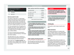
Key of the Schematic diagram ››› Fig. 171:
PinMeaning
1Left turn signal
2Rear fog light
3Earth, pins 1, 2, 4 to 8
4Right turn signal
5Tail light, right
6Brake lights
7Tail light, left
8Reverse lights
9Permanent live
10Cable without positive charge
11Earth, pin 10178
Page 181 of 284

Towing bracket deviceKey of the Schematic diagram
››› Fig. 171:
PinMeaning
12Unassigned
13Earth, pin 9 Electrical socket for trailer
The vehicle is fitted with a 13-pole power
socket for the electrical connection between
the trailer and the vehicle. If the system de-
tects that a trailer has been connected elec-
trically, the electrical equipment on the trailer
will receive voltage through this connection.
Pin 9 has a permanent live. This powers, for
example, the trailer's interior lighting. Pin 10
is only powered when the engine is running.
The charge wire (pin 10) charges, for exam-
ple, a caravan battery.
Pin 9 and 10 should not be connected to
each other to avoid discharging or damaging
the vehicle's battery.
The earth wires, pin 3, pin 11 and pin 13,
should never be connected to each other to
avoid overloading the electrical system.
If the trailer has a
7-contact connector , you
will need to use an adapter cable. In this case
the function corresponding to pin 10 will not
be available. Trailer maximum electricity consumption
Brake lights (total)84 Watts
Turn signal, on each side42 Watts
Side lights (total)100 Watts
Rear lights (total)42 Watts
Rear fog light42 Watts
Never exceed the values indicated!
Note
● If the rear lights of the trailer are not cor-
rectly connected, the vehicle electronics may
be damaged.
● If the trailer absorbs excessive electric cur-
rent, the vehicle electronics may be dam-
aged.
● Never connect the trailer's electric system
directly to the electrical connections of the
tail lights or any other power sources. Only
use the connections intended for providing
electric current to the trailer. Ball coupling of towing bracket*
The ball coupling is provided with instruc-
tions on fitting and removing the ball cou-
pling of the towing bracket. WARNING
The towing bracket ball coupling must be
stored securely in the luggage compartment
to prevent them being flung through the vehi-
cle and causing injury. Note
● By law, the ball coupling must be removed
if a trailer is not being towed if it obscures
the number plate. Driving tips
Driving with a trailer always requires extra
care.
Weight distribution
The weight distribution of a loaded trailer
with an unladen vehicle is very unfavourable.
However, if this cannot be avoided, drive ex-
tra slowly to allow for the unbalanced weight
distribution.
Speed
The stability of the vehicle and trailer is re-
duced with increasing speed. For this reason,
it is advisable not to drive at the maximum
permissible speed in an unfavourable road,
weather or wind conditions. This applies es-
pecially when driving downhill.
»
179
Technical specifications
Advice
Operation
Safety
The essentials
Page 182 of 284

Operation
You should always reduce speed immediately
if the trailer shows the slightest sign of snak-
ing . Never try to stop the “snaking” by in-
c r
easing speed.
Always brake in due course. If the trailer has
an overrun brake, apply the brakes gen
tly at
first and then, firmly. This will prevent the
jerking that can be caused by locking of trail-
er wheels. Select a low gear in due course
before going down a steep downhill. This en-
ables you to use the engine braking to slow
down the vehicle.
Reheating
At very high temperatures and during pro-
longed slopes, driving in a low gear and high
engine speed, always monitor the coolant
temperature gauge ››› page 71.
Electronic stability control*
The ESC* system helps to stabilise the trailer
in case of skidding or rocking. Retrofitting a towing bracket*
Fig. 172
Attachment points for towing brack-
et. If a towing bracket is to be fitted after the ve-
hicle is purchased, this must be completed
according to the instructions of the towing
bracket manufacturer.The attachment points for the towing bracket
A are on the lower part of the vehicle.
The distance between the centre of the ball
coupling and the ground should never be
lower than the indicated value, even with a
fully loaded vehicle and including the maxi-
mum drawbar load.
Elevation values for securing the towing
bracket:
B65 mm (minimum)
C350 mm to 420 mm (fully laden vehicle)
D1040 mm
E317 mm
FLEON/LEON SCLEON ST
319 mm596 mm Fitting a towing bracket
●
Driving with a trailer involves an extra effort
for the vehicle. Therefore, before fitting a
towing bracket, please contact a Technical
Service to check whether your cooling system
needs modification.
● The legal requirements in your country
must be observed (e.g. the fitting of a sepa-
rate control lamp).
● Certain vehicle components, e.g. the rear
bumper, must be removed and reinstalled.
The towing bracket securing bolts must be
180
Page 183 of 284

Towing bracket device
tightened using a torque wrench, and a pow-
er socket must be connected to the vehicle
electrical system. This requires specialised
knowledge and tools.
● Figures in the illustration show the eleva-
tion value and the attachment points which
must be considered if you are retrofitting a
towing bracket. WARNING
The towing brackets should be fitted at a spe-
cialised workshop.
● If the towing bracket is incorrectly instal-
led, there is a serious danger of accident.
● For your own safety, please observe the tow
bracket manufacturer's instructions. CAUTION
● If the power socket is incorrectly installed,
this could cause damage to the vehicle elec-
trical system. Note
● SEAT recommends that the towing hooks
be fitted at a specialised workshop. Consult
your SEAT dealer in case additional modifica-
tions to your vehicle are necessary.
● Due to the specific design of the exhaust,
the fitting of a conventional towing hook is
not recommended for some sportier versions.
Please consult your Technical Service. 181Technical specifications
Advice
Operation
Safety
The essentials
Page 184 of 284

Advice
Advice
Care and maintenance
Accessories and modifications to the vehicle
Accessories, replacement parts and
repairs Always ask your dealer or specialist retailer
for advice before purchasing accessories and
replacement parts.
Your vehicle is designed to offer a high
standard of active and passive safety. For this
reason, we recommend that you ask a SEAT
Official Service for advice before fitting ac-
cessories or replacement parts. Your SEAT Of-
ficial Service has the latest information from
the manufacturer and can recommend acces-
sories and replacement parts which are suita-
ble for your requirements. They can also an-
swer any questions you might have regarding
official regulations.
We recommend you to use only
SEAT acces-
sories and
Genuine SEAT parts ®
. SEAT has
tested these parts and accessories for suita-
bility, reliability and safety. SEAT Official
Services have the necessary experience and
facilities to ensure that the parts are installed
correctly and professionally. Any
retro-fitted equipment which has a direct
effect on the vehicle and/or the way it is driv-
en, such as a cruise control system or elec-
tronically-controlled suspension, must be
approved for use in your vehicle and bear the
e mark (the European Union's authorisation
symbol).
If
any additional electrical devices are fitted
which do not serve to control the vehicle it-
self (for instance a refrigerator box, laptop or
ventilator fan, etc.), they must bear the
sign (manufacturer conformity declaration in
the European Union). WARNING
Accessories, for example telephone holders
or cup holders, should never be fitted on the
covers, or within the working range of the air-
bags. Otherwise, there is a danger of injury if
the airbag is triggered in an accident. Technical modifications
Modifications must always be carried out ac-
cording to our specifications.
Unauthorised modifications to the electronic
components, software, wiring or data transfer
in the vehicle may cause malfunctioning. Due
to the way the electronic components are
linked together in networks, other indirect
systems may be affected by the faults. This
can seriously impair safety, lead to excessivewear of components, and also invalidate your
vehicle registration documents.
You will appreciate that your SEAT dealership
cannot be held liable for any damage caused
by modifications and/or work performed in-
correctly.
We therefore recommend that all work should
be performed by a SEAT Official Service using
genuine SEAT parts
®
. WARNING
Incorrectly performed modifications or other
work on your vehicle can lead to malfunctions
and cause accidents. Two-way radios and office equipment
Radio transmitters (fixed installation)
Any retrofit installations of radio transmitters
in the vehicle require prior approval. SEAT
generally authorises in-vehicle installations
of approved types of radio transmitters provi-
ded that:
●
The aerial is installed correctly.
● The aerial is installed on the exterior of the
vehicle (and shielded cables are used togeth-
er with non-reflective aerial trimming).
● The effective transmitting power does not
exceed 10 Watts at the aerial base.
182