2014 NISSAN TEANA SEC
[x] Cancel search: SECPage 2531 of 4801
HOW TO USE THIS MANUALGI-3
< HOW TO USE THIS MANUAL >
C
D E
F
G H
I
J
K L
M B
GI
N
O PHOW TO USE THIS MANUAL
HOW TO USE THIS MANUAL
DescriptionINFOID:0000000009462967
This volume explains “Removal, Disassembly, Inst allation, Inspection and Adjustment” and “Trouble Diag-
noses”.
Te r m sINFOID:0000000009462968
• The captions WARNING and CAUTION warn you of steps that must be followed to prevent personal injury
and/or damage to some part of the vehicle.
WARNING indicates the possibility of personal injury if instructions are not followed.
CAUTION indicates the possibility of component damage if instructions are not followed.
BOLD TYPED STATEMENTS except WARNING and CAUTION give you helpful information.
Standard value: Tolerance at inspection and adjustment.
Limit value: The maximum or minimum limit val ue that should not be exceeded at inspection and adjust-
ment.
UnitsINFOID:0000000009462969
• The UNITS given in this manual are primarily expressed as the SI UNIT (International System of Unit), and
alternatively expressed in the metric system and in the yard/pound system.
Also with regard to tightening torque of bolts and nuts, there are descriptions both about range and about the
standard tightening torque.
“Example”
Range
Standard
ContentsINFOID:0000000009462970
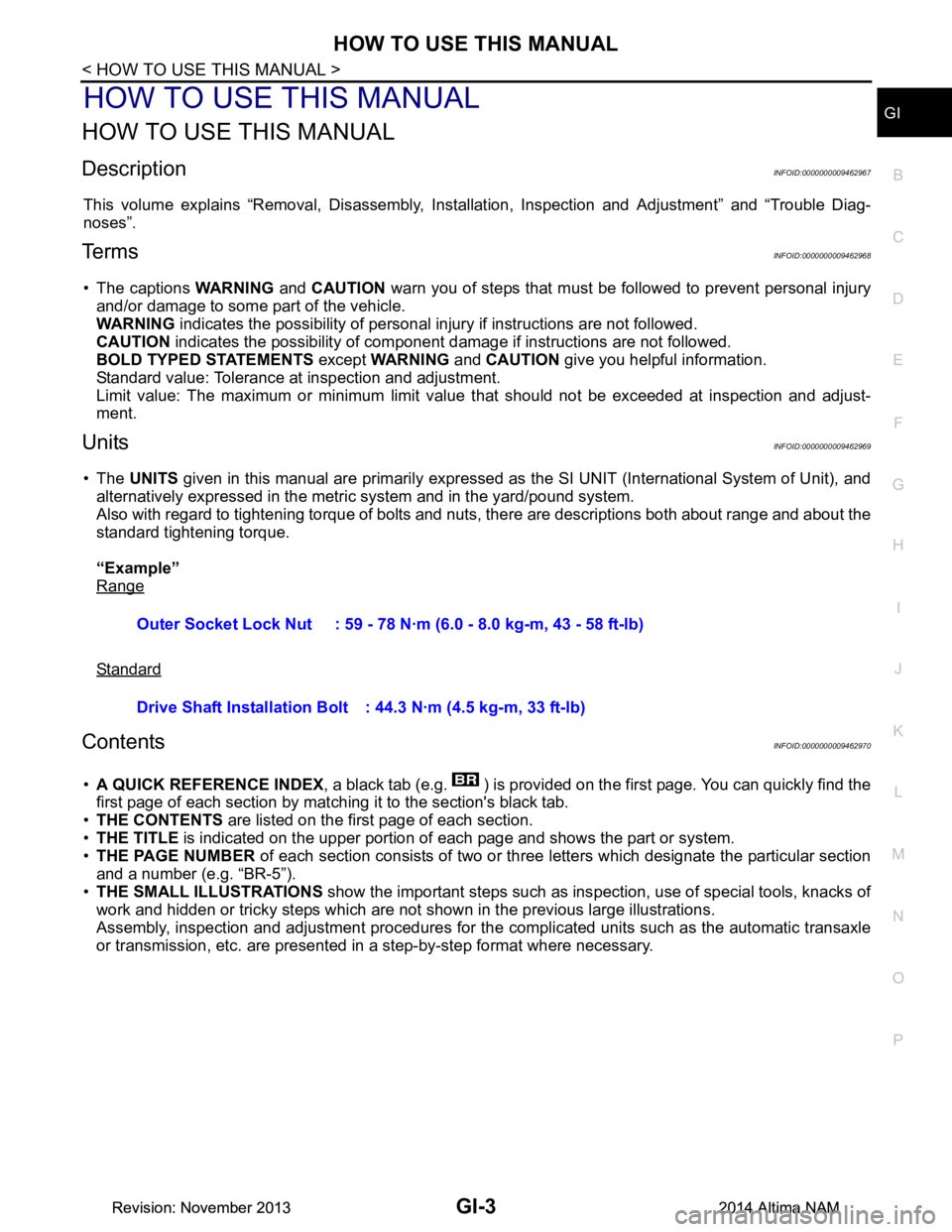
• A QUICK REFERENCE INDEX , a black tab (e.g. ) is provided on the first page. You can quickly find the
first page of each section by matching it to the section's black tab.
• THE CONTENTS are listed on the first page of each section.
• THE TITLE is indicated on the upper portion of each page and shows the part or system.
• THE PAGE NUMBER of each section consists of two or three letters which designate the particular section
and a number (e.g. “BR-5”).
• THE SMALL ILLUSTRATIONS show the important steps such as ins pection, use of special tools, knacks of
work and hidden or tricky steps which are not s hown in the previous large illustrations.
Assembly, inspection and adjustment procedures for the complicated units such as the automatic transaxle
or transmission, etc. are presented in a step-by-step format where necessary.
Outer Socket Lock Nut : 59 - 78 N·m (6.0 - 8.0 kg-m, 43 - 58 ft-lb)
Drive Shaft Installation Bolt : 44.3 N·m (4.5 kg-m, 33 ft-lb)
Revision: November 20132014 Altima NAMRevision: November 20132014 Altima NAM
Page 2532 of 4801
GI-4
< HOW TO USE THIS MANUAL >
HOW TO USE THIS MANUAL
Relation between Illustrations and Descriptions
INFOID:0000000009462971
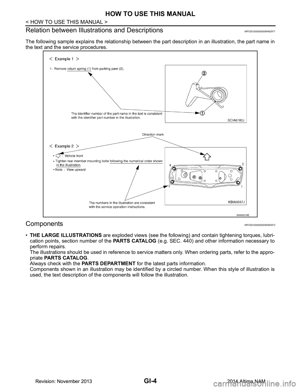
The following sample explains the relationship between t he part description in an illustration, the part name in
the text and the service procedures.
ComponentsINFOID:0000000009462972
• THE LARGE ILLUSTRATIONS are exploded views (see the following) and contain tightening torques, lubri-
cation points, section number of the PARTS CATALOG (e.g. SEC. 440) and other information necessary to
perform repairs.
The illustrations should be used in reference to service matters only. When ordering parts, refer to the appro-
priate PARTS CATALOG .
Always check with the PARTS DEPARTMENT for the latest parts information.
Components shown in an illustration may be identified by a circled number. When this style of illustration is
used, the text description of the components will follow the illustration.
SAIA0519E
Revision: November 20132014 Altima NAMRevision: November 20132014 Altima NAM
Page 2534 of 4801
GI-6
< HOW TO USE THIS MANUAL >
HOW TO FOLLOW TROUBLE DIAGNOSES
HOW TO FOLLOW TROUBLE DIAGNOSES
DescriptionINFOID:0000000009462973
NOTICE:
Trouble diagnoses indicate work procedures required to diagnose problems effectively. Observe the following
instructions before diagnosing.
• Before performing trouble diagnoses, read the “Work Flow” in each section.
• After repairs, re-check that the problem has been completely eliminated.
• Refer to Component Parts and Harness Connector Locat ion for the Systems described in each section for
identification/location of components and harness connectors.
• When checking circuit continuity, ignition switch should be OFF.
• Refer to the Circuit Diagram for quick pinpoint check.
If you need to check circuit continui ty between harness connectors in more detail, such as when a sub-har-
ness is used, refer to Wiring Diagram in each individual section and Harness Layout in PG section for identi-
fication of harness connectors.
• Before checking voltage at connectors, check battery voltage.
• After accomplishing the Diagnosis Procedures and Elec trical Components Inspection, make sure that all
harness connectors are reconnected as they were.
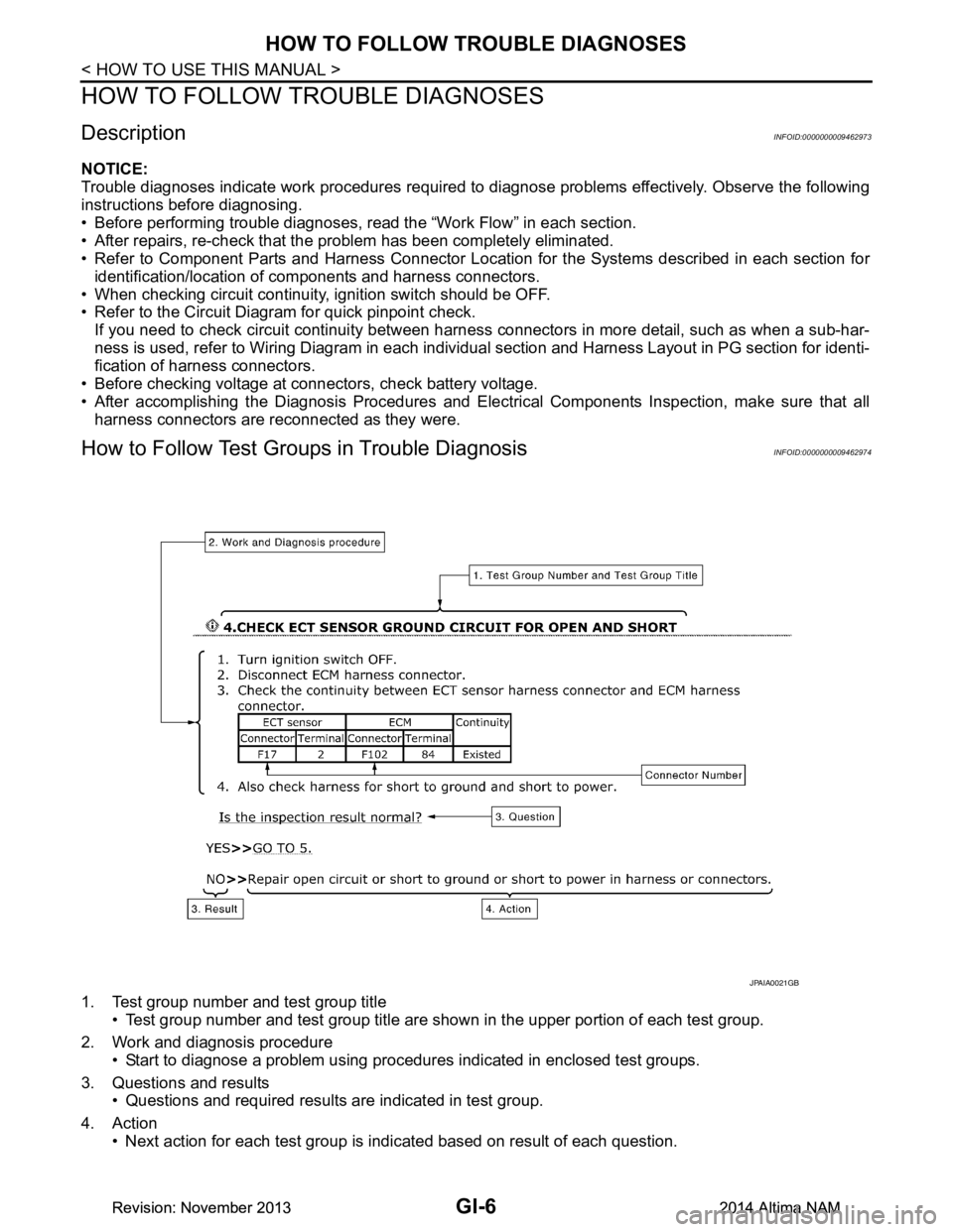
How to Follow Test Grou ps in Trouble DiagnosisINFOID:0000000009462974
1. Test group number and test group title
• Test group number and test group title are s hown in the upper portion of each test group.
2. Work and diagnosis procedure • Start to diagnose a problem using procedur es indicated in enclosed test groups.
3. Questions and results • Questions and required results are indicated in test group.
4. Action • Next action for each test group is indicated based on result of each question.
JPAIA0021GB
Revision: November 20132014 Altima NAMRevision: November 20132014 Altima NAM
Page 2537 of 4801
HOW TO READ WIRING DIAGRAMSGI-9
< HOW TO USE THIS MANUAL >
C
D E
F
G H
I
J
K L
M B
GI
N
O PHOW TO READ WIRING DIAGRAMS
Connector symbolsINFOID:0000000009462976
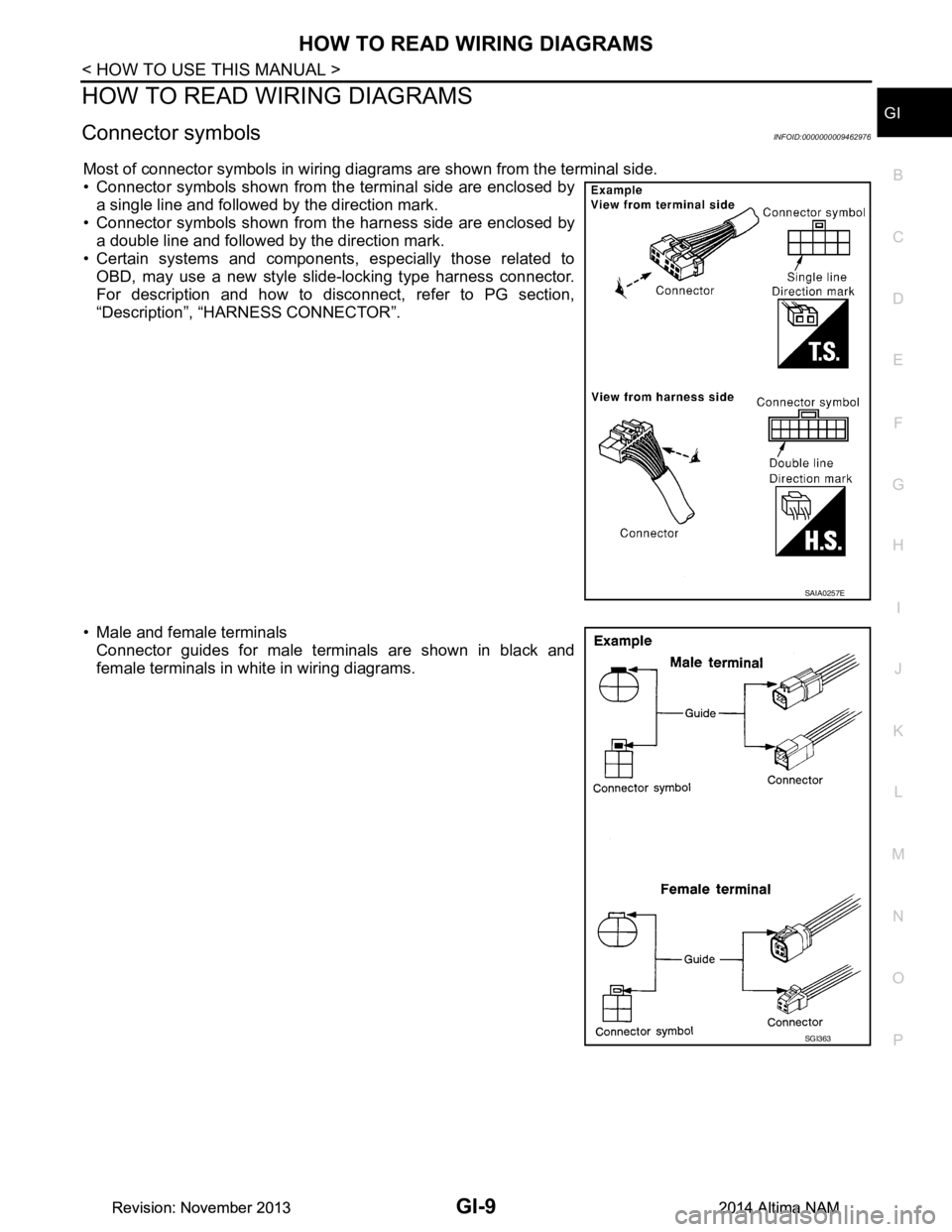
Most of connector symbols in wiring diagrams are shown from the terminal side.
• Connector symbols shown from the terminal side are enclosed by a single line and followed by the direction mark.
• Connector symbols shown from the harness side are enclosed by
a double line and followed by the direction mark.
• Certain systems and components, especially those related to
OBD, may use a new style slide-locking type harness connector.
For description and how to disconnect, refer to PG section,
“Description”, “HARNESS CONNECTOR”.
• Male and female terminals Connector guides for male terminals are shown in black and
female terminals in white in wiring diagrams.
SAIA0257E
SGI363
Revision: November 20132014 Altima NAMRevision: November 20132014 Altima NAM
Page 2541 of 4801

ABBREVIATIONSGI-13
< HOW TO USE THIS MANUAL >
C
D E
F
G H
I
J
K L
M B
GI
N
O PABBREVIATIONS
Abbreviation ListINFOID:0000000009462979
The following ABBREVIATIONS are used:
A
B
C
D
ABBREVIATION DESCRIPTION A/C Air conditioner
A/C Air conditioning
A/F sensor Air fuel ratio sensor A/T Automatic transaxle/transmission
ABS Anti-lock braking system
ACCS Advance climate control system ACL Air cleaner
AP Accelerator pedal
APP Accelerator pedal position AV Audio visual
AVM Around view monitor
AWD All wheel drive
ABBREVIATION DESCRIPTION BARO Barometric pressureBCI Backup collision intervention
BCM Body control module
BLSD Brake limited slip differential BPP Brake pedal positionBSI Blind spot intervention
BSW Blind spot warning
ABBREVIATION DESCRIPTION CKP Crankshaft positionCL Closed loop
CMP Camshaft position CPP Clutch pedal positionCTP Closed throttle position
CVT Continuously variable transaxle/transmission
ABBREVIATION DESCRIPTION D
1Drive range first gear
D
2Drive range second gear
D
3Drive range third gear
D
4Drive range fourth gear
DCA Distance control assist
DDS Downhill drive support DFI Direct fuel injection system
DLC Data link connector
DTC Diagnostic trouble code
Revision: November 20132014 Altima NAMRevision: November 20132014 Altima NAM
Page 2545 of 4801

ABBREVIATIONSGI-17
< HOW TO USE THIS MANUAL >
C
D E
F
G H
I
J
K L
M B
GI
N
O P
W
1
2
3
4
5
6
VIN Vehicle identification number
VSS Vehicle speed sensor
ABBREVIATION DESCRIPTION WOT Wide open throttle
ABBREVIATION DESCRIPTION 1
11st range first gear
1
21st range second gear
1GR First gear
ABBREVIATION DESCRIPTION 2
12nd range first gear
2
22nd range second gear
2GR Second gear
2WD 2-wheel drive
ABBREVIATION DESCRIPTION 3GR Third gear
ABBREVIATION DESCRIPTION 4GR Fourth gear
4WAS Four wheel active steer 4WD Four wheel drive
ABBREVIATION DESCRIPTION 5GR Fifth gear
ABBREVIATION DESCRIPTION 6GR Sixth gear
ABBREVIATION DESCRIPTION
Revision: November 20132014 Altima NAMRevision: November 20132014 Altima NAM
Page 2554 of 4801
GI-26
< PRECAUTION >
PRECAUTIONS
PRECAUTION
PRECAUTIONS
DescriptionINFOID:0000000009462991
Observe the following precautions to ensure safe and proper servicing. These precautions are not
described in each individual section.
Precaution for Supplemental Restraint Syst em (SRS) "AIR BAG" and "SEAT BELT
PRE-TENSIONER"
INFOID:0000000009462992
The Supplemental Restraint System such as “A IR BAG” and “SEAT BELT PRE-TENSIONER”, used along
with a front seat belt, helps to reduce the risk or severi ty of injury to the driver and front passenger for certain
types of collision. Information necessary to service the system safely is included in the SR and SB section of
this Service Manual.
WARNING:
• To avoid rendering the SRS inopera tive, which could increase the risk of personal injury or death in
the event of a collision which would result in air bag inflation, all maintenance must be performed by
an authorized NISS AN/INFINITI dealer.
• Improper maintenance, including in correct removal and installation of the SRS, can lead to personal
injury caused by unintent ional activation of the system. For re moval of Spiral Cable and Air Bag
Module, see the SR section.
• Do not use electrical test equipmen t on any circuit related to the SRS unless instructed to in this
Service Manual. SRS wiring harn esses can be identified by yellow and/or orange harnesses or har-
ness connectors.
PRECAUTIONS WHEN USING POWER TOOLS (AIR OR ELECTRIC) AND HAMMERS
WARNING:
• When working near the Airbag Diagnosis Sensor Unit or other Airbag System sensors with the Igni-
tion ON or engine running, DO NOT use air or electri c power tools or strike near the sensor(s) with a
hammer. Heavy vibration could activate the sensor( s) and deploy the air bag(s), possibly causing
serious injury.
• When using air or electric power tools or hammers , always switch the Ignition OFF, disconnect the
battery and wait at least 3 minutes before performing any service.
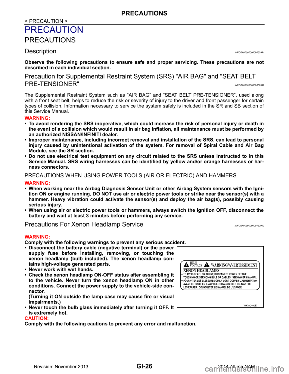
Precautions For Xeno n Headlamp ServiceINFOID:0000000009462993
WARNING:
Comply with the following warnings to prevent any serious accident.
• Disconnect the battery cable (n egative terminal) or the power
supply fuse before in stalling, removing, or touching the
xenon headlamp (bulb included) . The xenon headlamp con-
tains high-voltage generated parts.
• Never work with wet hands.
• Check the xenon headlamp ON-OFF status after assembling it to the vehicle. Never turn the xenon headlamp ON in other
conditions. Connect the power supply to the vehicle-side con-
nector.
(Turning it ON outside the la mp case may cause fire or visual
impairments.)
• Never touch the bulb glass immediately after turning it OFF. It is extremely hot.
CAUTION:
Comply with the following cautions to prevent any error and malfunction.
WKIA0460E
Revision: November 20132014 Altima NAMRevision: November 20132014 Altima NAM
Page 2555 of 4801
PRECAUTIONSGI-27
< PRECAUTION >
C
D E
F
G H
I
J
K L
M B
GI
N
O P
• Install the xenon bulb secure ly. (Insufficient bulb socket
installation may melt the bu lb, the connector, the housing,
etc, by high-voltage leakage or corona discharge.)
• Never perform HID circuit inspection with a tester.
• Never touch the xenon bulb gl ass with hands. Never put oil
and grease on it.
• Dispose of the used xenon bulb after packing it in thick vinyl
without breaking it.
• Never wipe out dirt and contam ination with organic solvent
(thinner, gasoline, etc.).
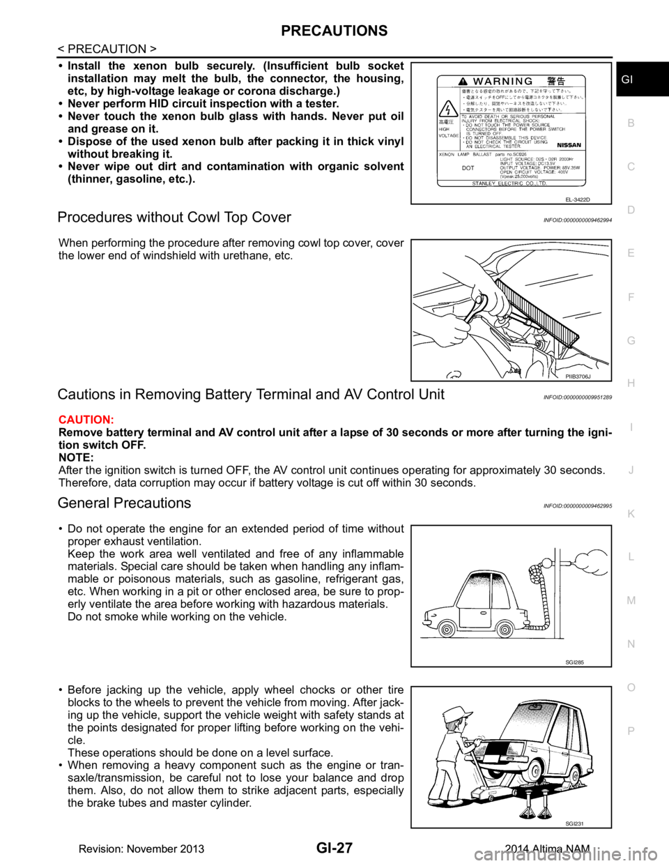
Procedures without Cowl Top CoverINFOID:0000000009462994
When performing the procedure after removing cowl top cover, cover
the lower end of windshield with urethane, etc.
Cautions in Removing Battery Terminal and AV Control UnitINFOID:0000000009951289
CAUTION:
Remove battery terminal and AV control unit after a lapse of 30 seconds or more after turning the igni-
tion switch OFF.
NOTE:
After the ignition switch is turned OFF, the AV cont rol unit continues operating for approximately 30 seconds.
Therefore, data corruption may occur if battery voltage is cut off within 30 seconds.
General PrecautionsINFOID:0000000009462995
• Do not operate the engine for an extended period of time without proper exhaust ventilation.
Keep the work area well ventilated and free of any inflammable
materials. Special care should be taken when handling any inflam-
mable or poisonous materials, such as gasoline, refrigerant gas,
etc. When working in a pit or ot her enclosed area, be sure to prop-
erly ventilate the area before working with hazardous materials.
Do not smoke while working on the vehicle.
• Before jacking up the vehicle, apply wheel chocks or other tire blocks to the wheels to prevent t he vehicle from moving. After jack-
ing up the vehicle, support the vehicle weight with safety stands at
the points designated for proper lifting before working on the vehi-
cle.
These operations should be done on a level surface.
• When removing a heavy component such as the engine or tran-
saxle/transmission, be careful not to lose your balance and drop
them. Also, do not allow them to strike adjacent parts, especially
the brake tubes and master cylinder.
EL-3422D
PIIB3706J
SGI285
SGI231
Revision: November 20132014 Altima NAMRevision: November 20132014 Altima NAM