2014 NISSAN TEANA SEC
[x] Cancel search: SECPage 2454 of 4801
FAX-2
< PRECAUTION >
PRECAUTIONS
PRECAUTION
PRECAUTIONS
Precaution for Supplemental Restraint System (SRS) "AIR BAG" and "SEAT BELT
PRE-TENSIONER"
INFOID:0000000009951700
The Supplemental Restraint System such as “A IR BAG” and “SEAT BELT PRE-TENSIONER”, used along
with a front seat belt, helps to reduce the risk or severi ty of injury to the driver and front passenger for certain
types of collision. Information necessary to service the system safely is included in the SR and SB section of
this Service Manual.
WARNING:
• To avoid rendering the SRS inopera tive, which could increase the risk of personal injury or death in
the event of a collision which would result in air bag inflation, all maintenance must be performed by
an authorized NISS AN/INFINITI dealer.
• Improper maintenance, including in correct removal and installation of the SRS, can lead to personal
injury caused by unintent ional activation of the system. For re moval of Spiral Cable and Air Bag
Module, see the SR section.
• Do not use electrical test equipmen t on any circuit related to the SRS unless instructed to in this
Service Manual. SRS wiring harn esses can be identified by yellow and/or orange harnesses or har-
ness connectors.
PRECAUTIONS WHEN USING POWER TOOLS (AIR OR ELECTRIC) AND HAMMERS
WARNING:
• When working near the Airbag Diagnosis Sensor Unit or other Airbag System sensors with the Igni-
tion ON or engine running, DO NOT use air or electri c power tools or strike near the sensor(s) with a
hammer. Heavy vibration could activate the sensor( s) and deploy the air bag(s), possibly causing
serious injury.
• When using air or electric power tools or hammers , always switch the Ignition OFF, disconnect the
battery and wait at least three minutes before performing any service.
Precautions for Drive ShaftINFOID:0000000009464432
Observe the following precautions when disassembling and assembling drive shaft.
• Joint sub-assembly does not disass emble because it is non-overhaul parts.
• Perform work in a location which is as dust-free as possible.
• Before disassembling and assembling, clean the outside of parts.
• Prevention of the entry of foreign objects must be tak en into account during disassembly of the service loca-
tion.
• Disassembled parts must be carefully reassembled in the correct order. If work is interrupted, a clean cover must be placed over parts.
• Paper shop cloths must be used. Fabric shop cloths must not be used because of the danger of lint adhering
to parts.
• Disassembled parts (except for rubber parts) should be cleaned with kerosene which shall be removed by
blowing with air or wiping with paper shop cloths.
Revision: November 20132014 Altima NAM
Page 2463 of 4801
FRONT DRIVE SHAFTFAX-11
< REMOVAL AND INSTALLATION >
CEF
G H
I
J
K L
M A
B
FA X
N
O P
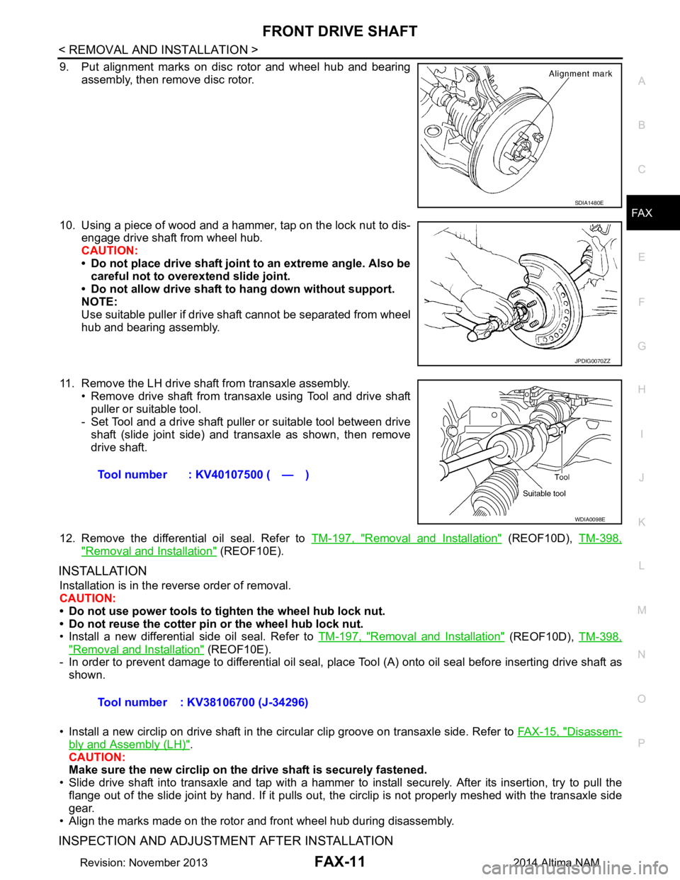
9. Put alignment marks on disc rotor and wheel hub and bearing assembly, then remove disc rotor.
10. Using a piece of wood and a hammer, tap on the lock nut to dis- engage drive shaft from wheel hub.
CAUTION:
• Do not place drive shaft joint to an extreme angle. Also be careful not to over extend slide joint.
• Do not allow drive shaft to hang down without support.
NOTE:
Use suitable puller if drive shaft cannot be separated from wheel
hub and bearing assembly.
11. Remove the LH drive shaf t from transaxle assembly.
• Remove drive shaft from transaxle using Tool and drive shaft puller or suitable tool.
- Set Tool and a drive shaft puller or suitable tool between drive
shaft (slide joint side) and transaxle as shown, then remove
drive shaft.
12. Remove the differential oil seal. Refer to TM-197, "Removal and Installation"
(REOF10D), TM-398,
"Removal and Installation" (REOF10E).
INSTALLATION
Installation is in the reverse order of removal.
CAUTION:
• Do not use power tools to ti ghten the wheel hub lock nut.
• Do not reuse the cotter pin or the wheel hub lock nut.
• Install a new differential side oil seal. Refer to TM-197, "Removal and Installation"
(REOF10D), TM-398,
"Removal and Installation" (REOF10E).
- In order to prevent damage to differential oil seal, plac e Tool (A) onto oil seal before inserting drive shaft as
shown.
• Install a new circlip on drive shaft in the circular clip groove on transaxle side. Refer to FAX-15, "Disassem-
bly and Assembly (LH)".
CAUTION:
Make sure the new circlip on the drive shaft is securely fastened.
• Slide drive shaft into transaxle and tap with a hammer to install securely. After its insertion, try to pull the
flange out of the slide joint by hand. If it pulls out, t he circlip is not properly meshed with the transaxle side
gear.
• Align the marks made on the rotor and front wheel hub during disassembly.
INSPECTION AND ADJUSTMENT AFTER INSTALLATION
SDIA1480E
JPDIG0070ZZ
Tool number : KV40107500 ( — )
WDIA0098E
Tool number : KV38106700 (J-34296)
Revision: November 20132014 Altima NAM
Page 2466 of 4801
FAX-14
< REMOVAL AND INSTALLATION >
FRONT DRIVE SHAFT
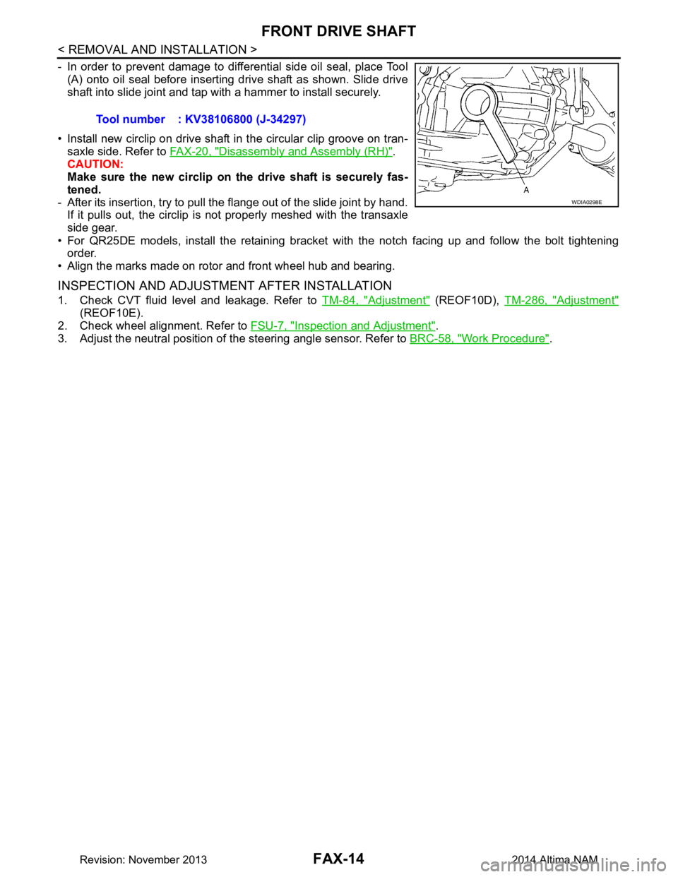
- In order to prevent damage to differential side oil seal, place Tool(A) onto oil seal before inserting drive shaft as shown. Slide drive
shaft into slide joint and tap with a hammer to install securely.
• Install new circlip on drive shaft in the circular clip groove on tran- saxle side. Refer to FAX-20, "Disassembly and Assembly (RH)"
.
CAUTION:
Make sure the new circlip on the drive shaft is securely fas-
tened.
- After its insertion, try to pull the flange out of the slide joint by hand. If it pulls out, the circlip is not properly meshed with the transaxle
side gear.
• For QR25DE models, install the retaining bracket with the notch facing up and follow the bolt tightening
order.
• Align the marks made on rotor and front wheel hub and bearing.
INSPECTION AND ADJUSTMENT AFTER INSTALLATION
1. Check CVT fluid level and leakage. Refer to TM-84, "Adjustment" (REOF10D), TM-286, "Adjustment"
(REOF10E).
2. Check wheel alignment. Refer to FSU-7, "Inspection and Adjustment"
.
3. Adjust the neutral position of the steering angle sensor. Refer to BRC-58, "Work Procedure"
.
Tool number : KV38106800 (J-34297)
WDIA0298E
Revision: November 20132014 Altima NAM
Page 2469 of 4801
FRONT DRIVE SHAFTFAX-17
< UNIT DISASSEMBLY AND ASSEMBLY >
CEF
G H
I
J
K L
M A
B
FA X
N
O P
Slide Joint Housing
• Make sure there are no compression scars, cracks or
fractures or unusual wear of ball rolling surface.
• Make sure there is no damage to shaft screws.
• Make sure there is no deformation of boot installation parts.
Ball Cage
• Make sure there are no compression scars, cracks, fractures of sliding surface.
Steel Ball
• Make sure there are no compression scars , cracks, fractures or unusual wear.
Inner Race
• Check ball sliding surface for compression scars, cracks or fractures.
• Make sure there is no damage to serrated part.
CAUTION:
If there are any irregular condit ions in the component, replace with a new set of joint sub-assembly,
ball cage, steel ball and inner race.
Damper
• Check damper for cracks or wear. Install damper with new damper bands.
ASSEMBLY
Transaxle Side
1. Install new boot and new small boot band on shaft.
CAUTION:
• Cover drive shaft serration with tape to prevent damage to boot during installation.
• Do not reuse boot band and boot.
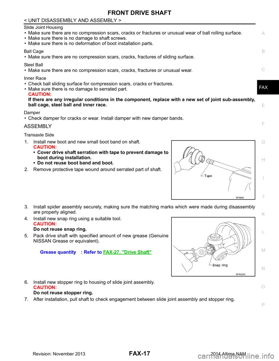
2. Remove protective tape wound around serrated part of shaft.
3. Install spider assembly securely, making sure the matching marks which were made during disassembly are properly aligned.
4. Install new snap ring using a suitable tool. CAUTION:
Do not reuse snap ring.
5. Pack drive shaft with specified amount of new grease (Genuine NISSAN Grease or equivalent).
6. Install new stopper ring to housing of slide joint assembly. CAUTION:
Do not reuse stopper ring.
7. After installation, pull shaft to check engagement between slide joint assembly and stopper ring.
SFA800
Grease quantity : Refer to FAX-27, "Drive Shaft"
SFA023A
Revision: November 20132014 Altima NAM
Page 2470 of 4801
FAX-18
< UNIT DISASSEMBLY AND ASSEMBLY >
FRONT DRIVE SHAFT
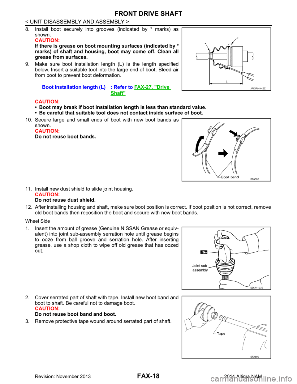
8. Install boot securely into grooves (indicated by * marks) asshown.
CAUTION:
If there is grease on boot mounting surfaces (indicated by *
marks) of shaft and housing, boot may come off. Clean all
grease from surfaces.
9. Make sure boot installation length (L) is the length specified below. Insert a suitable tool into the large end of boot. Bleed air
from boot to prevent boot deformation.
CAUTION:
• Boot may break if boot installation length is less than standard value.
• Be careful that suitable tool does not contact inside surface of boot.
10. Secure large and small ends of boot with new boot bands as shown.
CAUTION:
Do not reuse boot bands.
11. Install new dust shield to slide joint housing. CAUTION:
Do not reuse dust shield.
12. After installing housing and shaft, make sure boot posit ion is correct. If boot position is not correct, remove
old boot bands then reposition the boot and secure with new boot bands.
Wheel Side
1. Insert the amount of grease (Genuine NISSAN Grease or equiv-
alent) into joint sub-assembly serration hole until grease begins
to ooze from ball groove and serration hole. After inserting
grease, use a shop cloth to wipe off old grease that has oozed
out.
2. Cover serrated part of shaft with tape. Install new boot band and boot to shaft. Be careful not to damage boot.
CAUTION:
Do not reuse boot band and boot.
3. Remove protective tape wound around serrated part of shaft. Boot installation length (L) : Refer to
FAX-27, "Drive
Shaft"
JPDIF0144ZZ
SFA395
SDIA1127E
SFA800
Revision: November 20132014 Altima NAM
Page 2471 of 4801
FRONT DRIVE SHAFTFAX-19
< UNIT DISASSEMBLY AND ASSEMBLY >
CEF
G H
I
J
K L
M A
B
FA X
N
O P
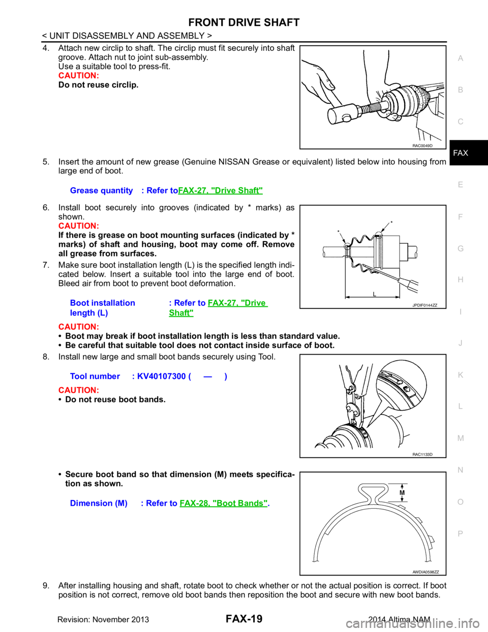
4. Attach new circlip to shaft. The circlip must fit securely into shaft groove. Attach nut to joint sub-assembly.
Use a suitable tool to press-fit.
CAUTION:
Do not reuse circlip.
5. Insert the amount of new grease (Genuine NISSAN Grease or equivalent) listed below into housing from
large end of boot.
6. Install boot securely into grooves (indicated by * marks) as shown.
CAUTION:
If there is grease on boot mounting surfaces (indicated by *
marks) of shaft and housing, boot may come off. Remove
all grease from surfaces.
7. Make sure boot installation length (L) is the specified length indi- cated below. Insert a suitable tool into the large end of boot.
Bleed air from boot to prevent boot deformation.
CAUTION:
• Boot may break if boot installation le ngth is less than standard value.
• Be careful that suitable tool does not contact inside surface of boot.
8. Install new large and small boot bands securely using Tool.
CAUTION:
• Do not reuse boot bands.
• Secure boot band so that dimension (M) meets specifica- tion as shown.
9. After installing housing and shaft, rotate boot to check whether or not the actual position is correct. If boot
position is not correct, remove old boot bands t hen reposition the boot and secure with new boot bands.
RAC0049D
Grease quantity : Refer toFAX-27, "Drive Shaft"
Boot installation
length (L) : Refer to
FAX-27, "Drive
Shaft"
Tool number : KV40107300 ( — )
JPDIF0144ZZ
RAC1133D
Dimension (M) : Refer to FAX-28, "Boot Bands".
AWDIA0598ZZ
Revision: November 20132014 Altima NAM
Page 2472 of 4801
FAX-20
< UNIT DISASSEMBLY AND ASSEMBLY >
FRONT DRIVE SHAFT
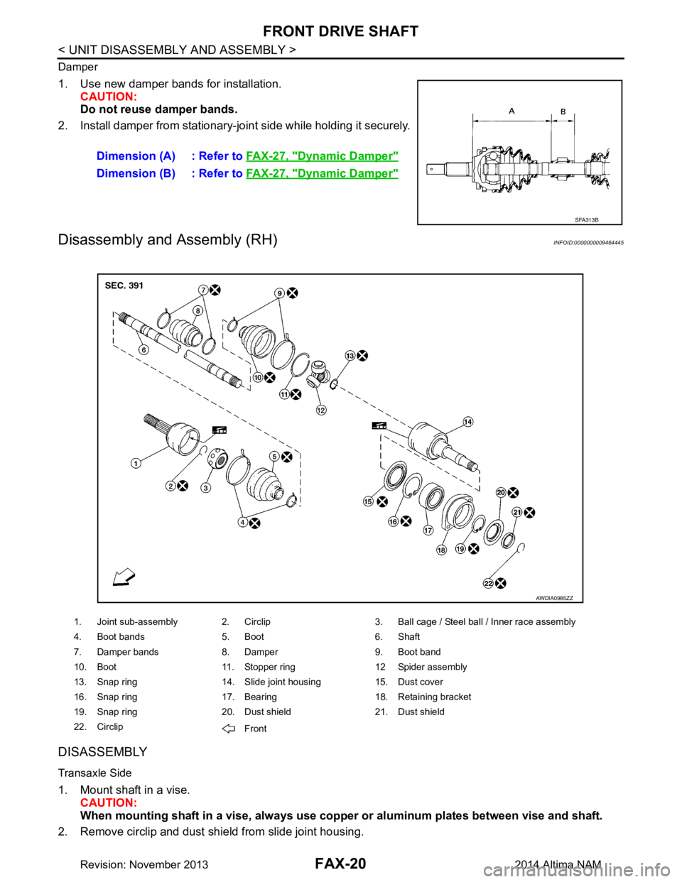
Damper
1. Use new damper bands for installation.CAUTION:
Do not reuse damper bands.
2. Install damper from stationary-joint side while holding it securely.
Disassembly and Assembly (RH)INFOID:0000000009464445
DISASSEMBLY
Transaxle Side
1. Mount shaft in a vise. CAUTION:
When mounting shaf t in a vise, always use copper or al uminum plates between vise and shaft.
2. Remove circlip and dust shield from slide joint housing. Dimension (A) : Refer to
FAX-27, "Dynamic Damper"
Dimension (B) : Refer to FAX-27, "Dynamic Damper"
SFA313B
1. Joint sub-assembly 2. Circlip 3. Ball cage / Steel ball / Inner race assembly
4. Boot bands 5. Boot 6. Shaft
7. Damper bands 8. Damper 9. Boot band
10. Boot 11. Stopper ring 12 Spider assembly
13. Snap ring 14. Slide joint housing 15. Dust cover
16. Snap ring 17. Bearing 18. Retaining bracket
19. Snap ring 20. Dust shield 21. Dust shield
22. Circlip Front
AWDIA0985ZZ
Revision: November 20132014 Altima NAM
Page 2475 of 4801
FRONT DRIVE SHAFTFAX-23
< UNIT DISASSEMBLY AND ASSEMBLY >
CEF
G H
I
J
K L
M A
B
FA X
N
O P
• Check damper for cracks or wear. Install damper with new damper bands.
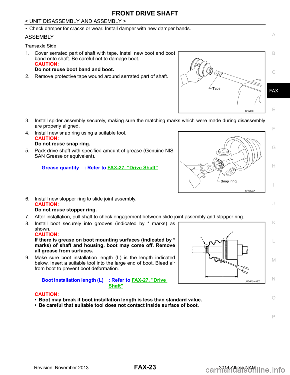
ASSEMBLY
Transaxle Side
1. Cover serrated part of shaft with tape. Install new boot and boot band onto shaft. Be careful not to damage boot.
CAUTION:
Do not reuse boot band and boot.
2. Remove protective tape wound around serrated part of shaft.
3. Install spider assembly securely, making sure the matching marks which were made during disassembly are properly aligned.
4. Install new snap ring using a suitable tool. CAUTION:
Do not reuse snap ring.
5. Pack drive shaft with specifi ed amount of grease (Genuine NIS-
SAN Grease or equivalent).
6. Install new stopper ring to slide joint assembly. CAUTION:
Do not reuse stopper ring.
7. After installation, pull shaft to check engagement between slide joint assembly and stopper ring.
8. Install boot securely into grooves (indicated by * marks) as shown.
CAUTION:
If there is grease on boot mounting surfaces (indicated by *
marks) of shaft and housing, boot may come off. Remove
all grease from surfaces.
9. Make sure boot installation length (L) is the length indicated below. Insert a suitable tool into the large end of boot. Bleed air
from boot to prevent boot deformation.
CAUTION:
• Boot may break if boot installation le ngth is less than standard value.
• Be careful that suitable tool does not contact inside surface of boot.
SFA800
Grease quantity : Refer to FAX-27, "Drive Shaft"
SFA023A
Boot installation length (L) : Refer to FAX-27, "Drive
Shaft"
JPDIF0144ZZ
Revision: November 20132014 Altima NAM