2014 NISSAN TEANA SEC
[x] Cancel search: SECPage 2476 of 4801
FAX-24
< UNIT DISASSEMBLY AND ASSEMBLY >
FRONT DRIVE SHAFT
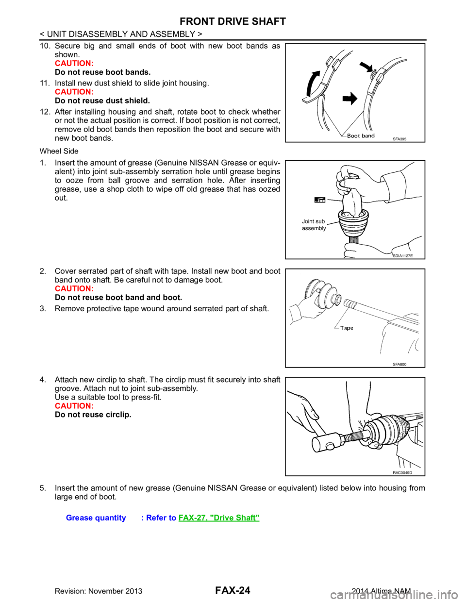
10. Secure big and small ends of boot with new boot bands asshown.
CAUTION:
Do not reuse boot bands.
11. Install new dust shield to slide joint housing. CAUTION:
Do not reuse dust shield.
12. After installing housing and shaft, rotate boot to check whether or not the actual position is corre ct. If boot position is not correct,
remove old boot bands then reposition the boot and secure with
new boot bands.
Wheel Side
1. Insert the amount of grease (Genuine NISSAN Grease or equiv-
alent) into joint sub-assembly serration hole until grease begins
to ooze from ball groove and serration hole. After inserting
grease, use a shop cloth to wipe off old grease that has oozed
out.
2. Cover serrated part of shaft with tape. Install new boot and boot band onto shaft. Be careful not to damage boot.
CAUTION:
Do not reuse boot band and boot.
3. Remove protective tape wound around serrated part of shaft.
4. Attach new circlip to shaft. The circlip must fit securely into shaft groove. Attach nut to joint sub-assembly.
Use a suitable tool to press-fit.
CAUTION:
Do not reuse circlip.
5. Insert the amount of new grease (Genuine NISSAN Grease or equivalent) listed below into housing from
large end of boot.
SFA395
SDIA1127E
SFA800
RAC0049D
Grease quantity : Refer to FAX-27, "Drive Shaft"
Revision: November 20132014 Altima NAM
Page 2477 of 4801
FRONT DRIVE SHAFTFAX-25
< UNIT DISASSEMBLY AND ASSEMBLY >
CEF
G H
I
J
K L
M A
B
FA X
N
O P
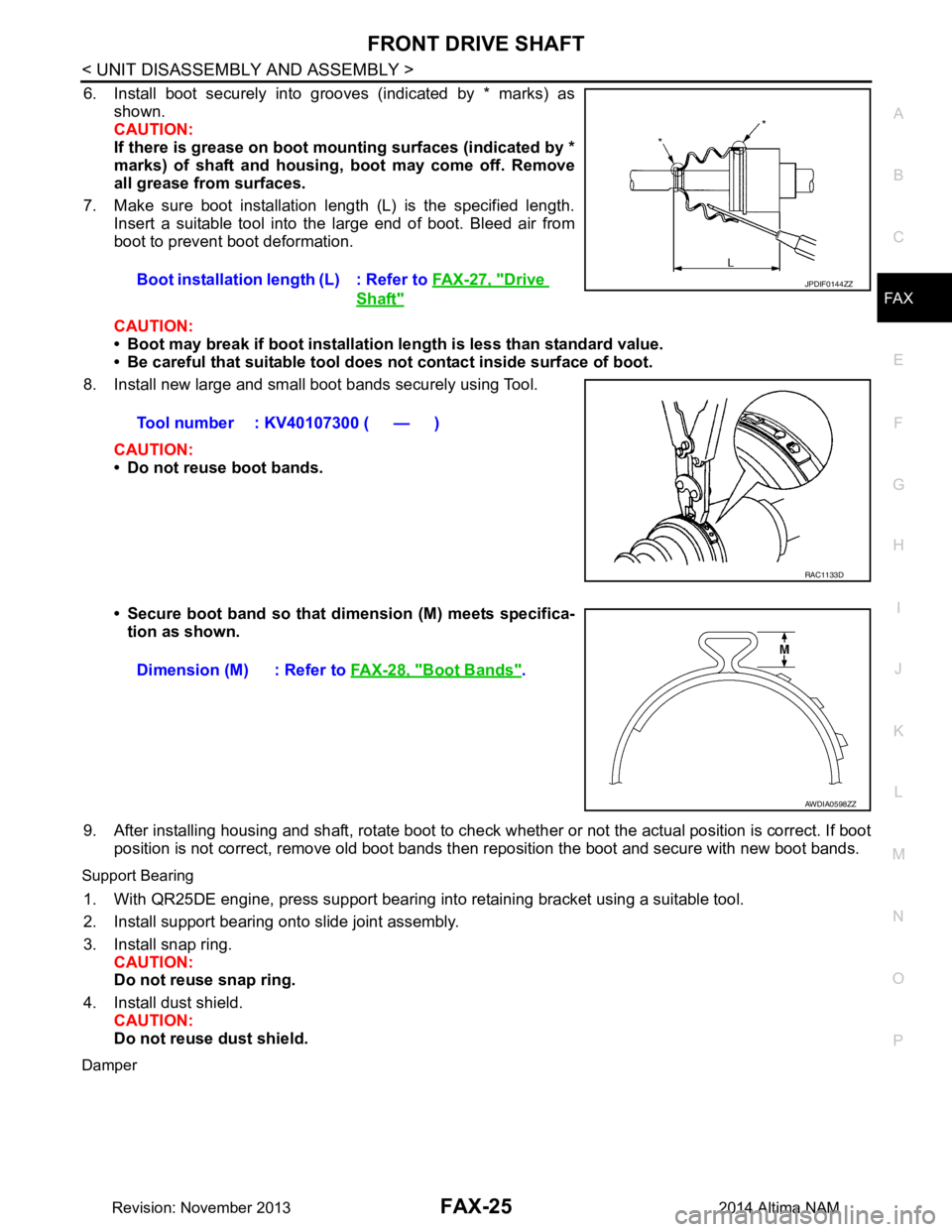
6. Install boot securely into grooves (indicated by * marks) as shown.
CAUTION:
If there is grease on boot mounting surfaces (indicated by *
marks) of shaft and housing, boot may come off. Remove
all grease from surfaces.
7. Make sure boot installation length (L) is the specified length. Insert a suitable tool into the large end of boot. Bleed air from
boot to prevent boot deformation.
CAUTION:
• Boot may break if boot installation le ngth is less than standard value.
• Be careful that suitable tool does not contact inside surface of boot.
8. Install new large and small boot bands securely using Tool.
CAUTION:
• Do not reuse boot bands.
• Secure boot band so that dimension (M) meets specifica- tion as shown.
9. After installing housing and shaft, rotate boot to check whether or not the actual position is correct. If boot
position is not correct, remove old boot bands t hen reposition the boot and secure with new boot bands.
Support Bearing
1. With QR25DE engine, press support bearing into retaining bracket using a suitable tool.
2. Install support bearing onto slide joint assembly.
3. Install snap ring. CAUTION:
Do not reuse snap ring.
4. Install dust shield. CAUTION:
Do not reuse dust shield.
Damper
Boot installation length (L) : Refer to FAX-27, "Drive
Shaft"
Tool number : KV40107300 ( — )
JPDIF0144ZZ
RAC1133D
Dimension (M) : Refer to FAX-28, "Boot Bands".
AWDIA0598ZZ
Revision: November 20132014 Altima NAM
Page 2478 of 4801
FAX-26
< UNIT DISASSEMBLY AND ASSEMBLY >
FRONT DRIVE SHAFT
1. Use new damper bands for installation.CAUTION:
Do not reuse damper bands.
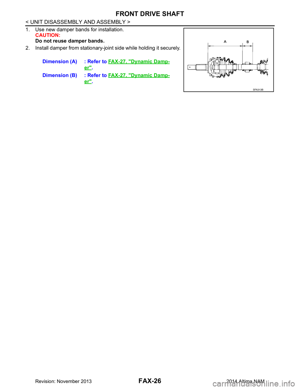
2. Install damper from stationary-joint side while holding it securely.
Dimension (A) : Refer to FAX-27, "Dynamic Damp-
er".
Dimension (B) : Refer to FAX-27, "Dynamic Damp-
er".
SFA313B
Revision: November 20132014 Altima NAM
Page 2481 of 4801
FL-1
ENGINE
C
D E
F
G H
I
J
K L
M
SECTION FL
A
FL
N
O P
CONTENTS
FUEL SYSTEM
PRECAUTION ................ ...............................2
PRECAUTIONS .............................................. .....2
Precaution for Supplemental Restraint System
(SRS) "AIR BAG" and "SEAT BELT PRE-TEN-
SIONER" ............................................................. ......
2
General Precaution ...................................................2
PREPARATION ............................................4
PREPARATION .............................................. .....4
Special Service Tool ........................................... ......4
Commercial Service Tool ..........................................4
PERIODIC MAINTENANCE ..........................5
FUEL SYSTEM ............................................... .....5
Inspection ............................................................ ......5
Quick Connector .......................................................5
REMOVAL AND INSTALLATION ................6
FUEL LEVEL SENSOR UNIT, FUEL FILTER
AND FUEL PUMP ASSEMBLY ..................... .....
6
Exploded View .................................................... ......6
Removal and Installation ...........................................6
Inspection ............................................................ ......9
FUEL TANK ........................................................10
Exploded View .................................................... ....10
Removal and Installation .........................................10
Inspection ............................................................ ....13
EVAP CANISTER ..............................................14
Exploded View .........................................................14
Removal and Installation .........................................14
Inspection ................................................................15
EVAP CANISTER FILTER ................................16
Exploded View .........................................................16
Removal and Installation .........................................16
EVAP CANISTER VENT CONTROL VALVE ...17
Exploded View .........................................................17
Removal and Installation .........................................17
EVAP CONTROL SYSTEM PRESSURE SEN-
SOR ...................................................................
18
Exploded View ..................................................... ....18
Removal and Installation .........................................18
UNIT DISASSEMBLY AND ASSEMBLY ....19
FUEL LEVEL SENSOR UNIT ...........................19
Disassembly and Assembly ................................. ....19
SERVICE DATA AND SPECIFICATIONS
(SDS) ............... .............................................
21
SERVICE DATA AND SPECIFICATIONS
(SDS) .................................................................
21
Fuel Tank ............................................................. ....21
Revision: November 20132014 Altima NAM
Page 2482 of 4801
FL-2
< PRECAUTION >
PRECAUTIONS
PRECAUTION
PRECAUTIONS
Precaution for Supplemental Restraint System (SRS) "AIR BAG" and "SEAT BELT
PRE-TENSIONER"
INFOID:0000000009951691
The Supplemental Restraint System such as “A IR BAG” and “SEAT BELT PRE-TENSIONER”, used along
with a front seat belt, helps to reduce the risk or severi ty of injury to the driver and front passenger for certain
types of collision. Information necessary to service the system safely is included in the SR and SB section of
this Service Manual.
WARNING:
• To avoid rendering the SRS inopera tive, which could increase the risk of personal injury or death in
the event of a collision which would result in air bag inflation, all maintenance must be performed by
an authorized NISS AN/INFINITI dealer.
• Improper maintenance, including in correct removal and installation of the SRS, can lead to personal
injury caused by unintent ional activation of the system. For re moval of Spiral Cable and Air Bag
Module, see the SR section.
• Do not use electrical test equipmen t on any circuit related to the SRS unless instructed to in this
Service Manual. SRS wiring harn esses can be identified by yellow and/or orange harnesses or har-
ness connectors.
PRECAUTIONS WHEN USING POWER TOOLS (AIR OR ELECTRIC) AND HAMMERS
WARNING:
• When working near the Airbag Diagnosis Sensor Unit or other Airbag System sensors with the Igni-
tion ON or engine running, DO NOT use air or electri c power tools or strike near the sensor(s) with a
hammer. Heavy vibration could activate the sensor( s) and deploy the air bag(s), possibly causing
serious injury.
• When using air or electric power tools or hammers , always switch the Ignition OFF, disconnect the
battery and wait at least three minutes before performing any service.
General PrecautionINFOID:0000000009460597
WARNING:
When replacing fuel line parts, be sure to observe the following.
• Put a “CAUTION: FLAMMABLE” sign in the work area.
• Be sure to work in a well ventilated area and have a CO
2 fire extinguisher.
• Do not smoke while working on the fuel system. Keep open flames and sparks away from the work
area.
CAUTION:
• Before removing fuel line parts, carry out the following procedures:
- Put drained fuel in an explosi on-proof container and put the lid on securely. Keep the container in
safe area.
- Release fuel pressure from the fuel lines. Refer to EC-182, "Work Procedure"
(QR25DE), EC-687,
"Work Procedure" (VQ35DE).
- Disconnect the battery ground cable.
• Always replace O-rings and clamps with new ones.
• Do not kink or twist tubes when they are being installed.
• Do not tighten hose clamps excessi vely to avoid damaging hoses.
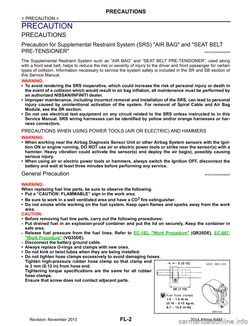
Tighten high-pressure rubber hose clamp so that clamp end
is 3 mm (0.12 in) from hose end.
Tightening torque specificati ons are the same for all rubber
hose clamps.
Ensure that screw does not contact adjacent parts.
MMA104A
Revision: November 20132014 Altima NAM
Page 2483 of 4801
PRECAUTIONSFL-3
< PRECAUTION >
C
D E
F
G H
I
J
K L
M A
FL
NP
O
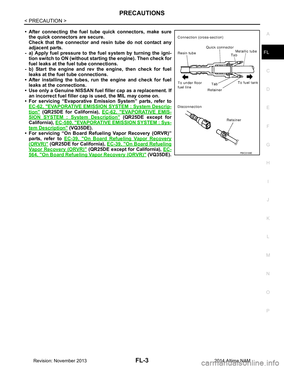
• After connecting the fuel tu
be quick connectors, make sure
the quick connectors are secure.
Check that the connector and r esin tube do not contact any
adjacent parts.
- a) Apply fuel pressure to the fu el system by turning the igni-
tion switch to ON (without star ting the engine). Then check for
fuel leaks at the fuel tube connections.
- b) Start the engine and rev the engine, then check for fuel leaks at the fuel tube connections.
• After installing the tubes, run the engine and check for fuel
leaks at the connections.
• Use only a Genuine NISSAN fuel filler cap as a replacement. If
an incorrect fuel fi ller cap is used, the MIL may come on.
• For servicing “Evaporative Emi ssion System” parts, refer to
EC-62, "EVAPORATIVE EMISSI ON SYSTEM : System Descrip-
tion" (QR25DE for California), EC-62, "EVAPORATIVE EMIS-
SION SYSTEM : System Description" (QR25DE except for
California), EC-580, "EVAPORATIVE EM ISSION SYSTEM : Sys-
tem Description" (VQ35DE).
• For servicing “On Board Refuel ing Vapor Recovery (ORVR)”
parts, refer to EC-39, "On Board Refueling Vapor Recovery
(ORVR)" (QR25DE for California), EC-39, "On Board Refueling
Vapor Recovery (ORVR)" (QR25DE except for California), EC-
564, "On Board Refueling Vapor Recovery (ORVR)" (VQ35DE).PBIC0199E
Revision: November 20132014 Altima NAM
Page 2485 of 4801
FUEL SYSTEMFL-5
< PERIODIC MAINTENANCE >
C
D E
F
G H
I
J
K L
M A
FL
NP
O
PERIODIC MAINTENANCE
FUEL SYSTEM
InspectionINFOID:0000000009460600
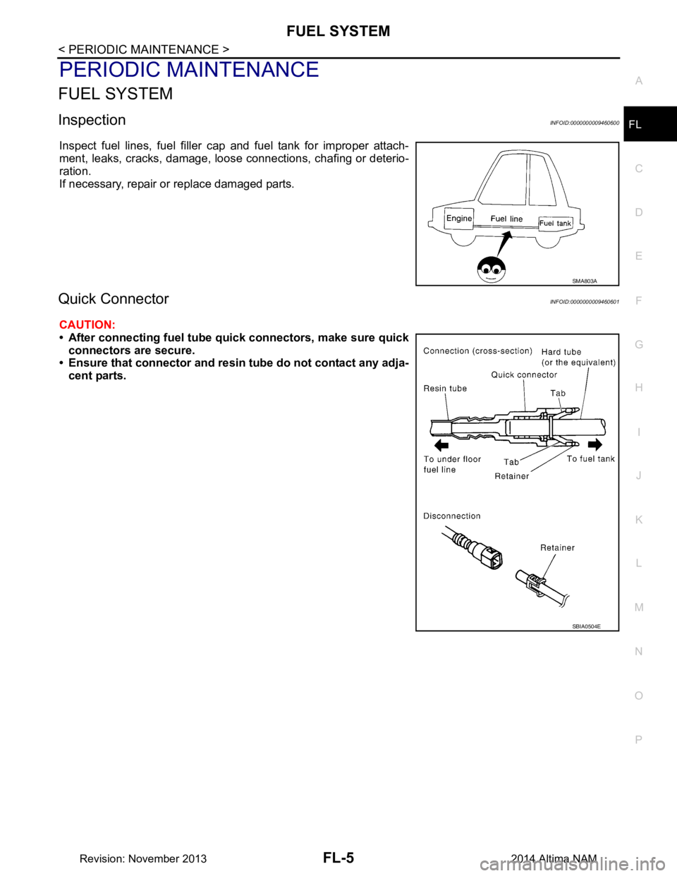
Inspect fuel lines, fuel filler cap and fuel tank for improper attach-
ment, leaks, cracks, damage, loos e connections, chafing or deterio-
ration.
If necessary, repair or replace damaged parts.
Quick ConnectorINFOID:0000000009460601
CAUTION:
• After connecting fuel tube qu ick connectors, make sure quick
connectors are secure.
• Ensure that connector and resin tube do not contact any adja-
cent parts.
SMA803A
SBIA0504E
Revision: November 20132014 Altima NAM
Page 2488 of 4801
FL-8
< REMOVAL AND INSTALLATION >
FUEL LEVEL SENSOR UNIT, FUEL FILTER AND FUEL PUMP ASSEMBLY
8. Remove the fuel level sensor, fuel filter, and fuel pump assembly
(A). Remove and discard the O-ring.
CAUTION:
• Do not bend the float arm during removal.
• Discard the O-ring. Do not reuse O-ring.
INSPECTION AFTER REMOVAL
Inspect the fuel level sensor, fuel filter, and fuel pump assembly for any defects and foreign materials. Replace
as necessary.
INSTALLATION
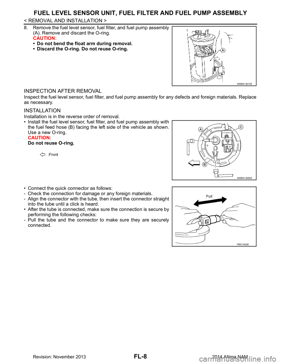
Installation is in the reverse order of removal.
• Install the fuel level sensor, fuel filter, and fuel pump assembly with the fuel feed hose (B) facing the left side of the vehicle as shown.
Use a new O-ring.
CAUTION:
Do not reuse O-ring.
• Connect the quick connector as follows:
- Check the connection for damage or any foreign materials.
- Align the connector with the tube, then insert the connector straight into the tube until a click is heard.
• After the tube is connected, make sure the connection is secure by performing the following checks:
- Pull the tube and the connector to make sure they are securely
connected.
AWBIA1307ZZ
:Front
AWBIA1308ZZ
PBIC1653E
Revision: November 20132014 Altima NAM