2014 NISSAN TEANA SEC
[x] Cancel search: SECPage 2492 of 4801
FL-12
< REMOVAL AND INSTALLATION >
FUEL TANK
8. Remove rear wheel and tire using power tool. Refer to WT-55, "Adjustment".
9. Remove rear brake pads. Refer to BR-38, "BRAKE PAD : Removal and Installation"
.
10. Remove rear torque members and rear disc brake rotor.
11. Disconnect rear parking brake shoe, and remove rear cables from toggle lever. Refer to PB-9, "Removal
and Installation".
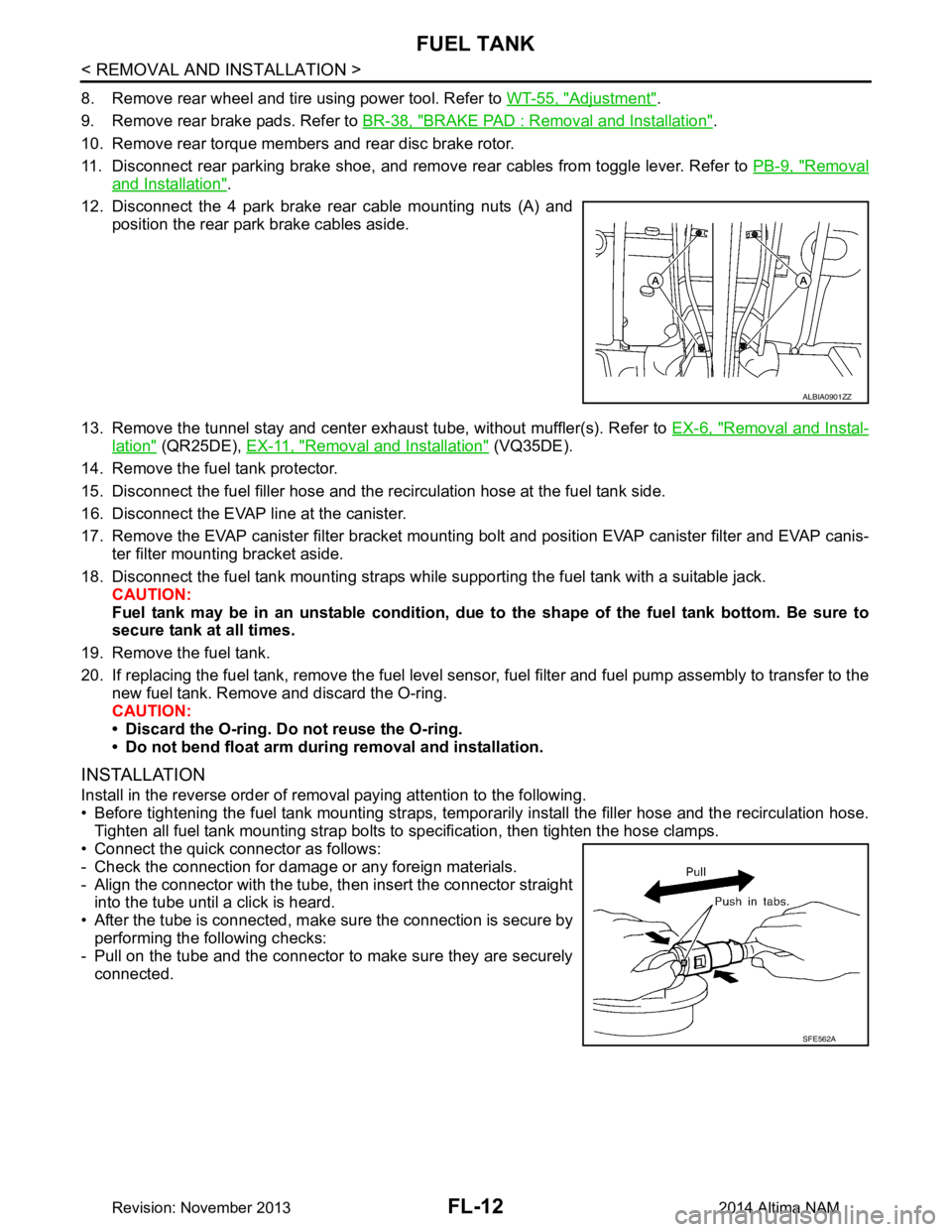
12. Disconnect the 4 park brake rear cable mounting nuts (A) and position the rear park brake cables aside.
13. Remove the tunnel stay and center exhaust tube, without muffler(s). Refer to EX-6, "Removal and Instal-
lation" (QR25DE), EX-11, "Removal and Installation" (VQ35DE).
14. Remove the fuel tank protector.
15. Disconnect the fuel filler hose and the recirculation hose at the fuel tank side.
16. Disconnect the EVAP line at the canister.
17. Remove the EVAP canister filter bracket mounti ng bolt and position EVAP canister filter and EVAP canis-
ter filter mounting bracket aside.
18. Disconnect the fuel tank mounting straps while supporting the fuel tank with a suitable jack. CAUTION:
Fuel tank may be in an unstable condition, due to the shape of the fuel tank bottom. Be sure to
secure tank at all times.
19. Remove the fuel tank.
20. If replacing the fuel tank, remove the fuel level sens or, fuel filter and fuel pump assembly to transfer to the
new fuel tank. Remove and discard the O-ring.
CAUTION:
• Discard the O-ring. Do not reuse the O-ring.
• Do not bend float arm during removal and installation.
INSTALLATION
Install in the reverse order of removal paying attention to the following.
• Before tightening the fuel tank mounting straps, tempor arily install the filler hose and the recirculation hose.
Tighten all fuel tank mounting strap bolts to specification, then tighten the hose clamps.
• Connect the quick connector as follows:
- Check the connection for damage or any foreign materials.
- Align the connector with the tube, then insert the connector straight into the tube until a click is heard.
• After the tube is connected, make sure the connection is secure by performing the following checks:
- Pull on the tube and the connector to make sure they are securely
connected.
ALBIA0901ZZ
SFE562A
Revision: November 20132014 Altima NAM
Page 2500 of 4801
FL-20
< UNIT DISASSEMBLY AND ASSEMBLY >
FUEL LEVEL SENSOR UNIT
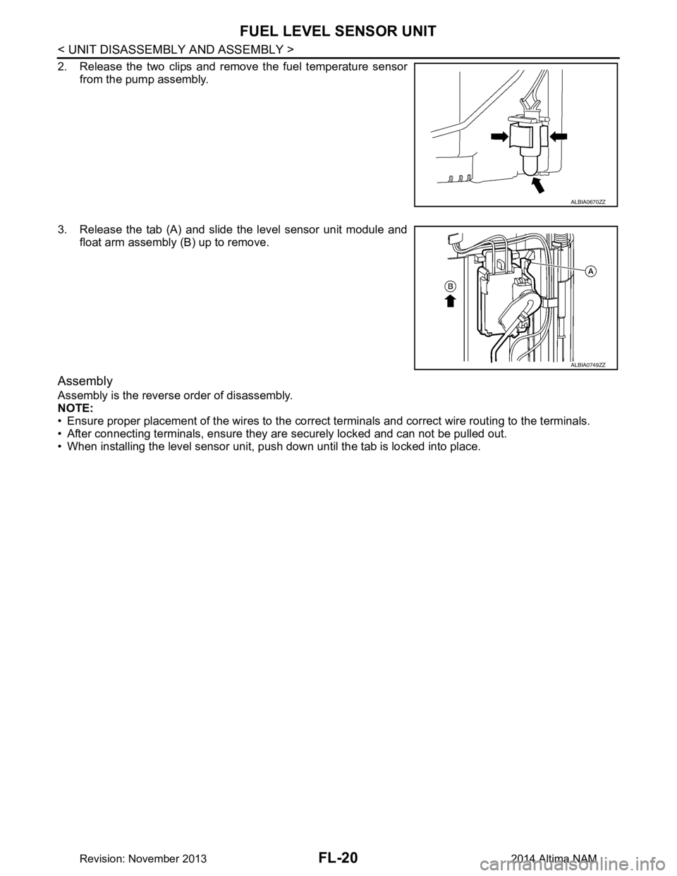
2. Release the two clips and remove the fuel temperature sensorfrom the pump assembly.
3. Release the tab (A) and slide the level sensor unit module and float arm assembly (B) up to remove.
Assembly
Assembly is the reverse order of disassembly.
NOTE:
• Ensure proper placement of the wires to the correct terminals and correct wire routing to the terminals.
• After connecting terminals, ensure they ar e securely locked and can not be pulled out.
• When installing the level sensor unit, push down until the tab is locked into place.
ALBIA0670ZZ
ALBIA0749ZZ
Revision: November 20132014 Altima NAM
Page 2502 of 4801
FSU-1
SUSPENSION
C
D
F
G H
I
J
K L
M
SECTION FSU
A
B
FSU
N
O PCONTENTS
FRONT SUSPENSION
PRECAUTION ................ ...............................2
PRECAUTIONS .............................................. .....2
Precaution for Supplemental Restraint System
(SRS) "AIR BAG" and "SEAT BELT PRE-TEN-
SIONER" ............................................................. ......
2
General Precautions .................................................2
Precaution for Procedure without Cowl Top Cover ......2
Precautions for Suspension ......................................2
PREPARATION ............................................4
PREPARATION .............................................. .....4
Special Service Tool ........................................... ......4
Commercial Service Tool ..........................................5
SYMPTOM DIAGNOSIS ...............................6
NOISE, VIBRATION AND HARSHNESS
(NVH) TROUBLESHOOTING ........................ .....
6
NVH Troubleshooting Chart ................................ ......6
PERIODIC MAINTENANCE ..........................7
FRONT SUSPENSION ASSEMBLY .............. .....7
Inspection and Adjustment .................................. ......7
REMOVAL AND INSTALLATION ................9
FRONT COIL SPRING AND STRUT ............. .....9
Exploded View .................................................... ......9
Removal and Installation ...........................................9
Disposal .............................................................. ....10
TRANSVERSE LINK .........................................11
Exploded View ..................................................... ....11
Removal and Installation .........................................11
FRONT STABILIZER ........................................14
Exploded View .........................................................14
Removal and Installation .........................................14
STEERING KNUCKLE ......................................17
Exploded View .........................................................17
Removal and Installation .........................................17
UNIT REMOVAL AND INSTALLATION ......19
FRONT SUSPENSION ASSEMBLY .................19
Exploded View ..................................................... ....19
Removal and Installation .........................................20
UNIT DISASSEMBLY AND ASSEMBLY ....22
FRONT COIL SPRING AND STRUT ................22
Disassembly and Assembly ................................. ....22
SERVICE DATA AND SPECIFICATIONS
(SDS) ............... .............................................
25
SERVICE DATA AND SPECIFICATIONS
(SDS) .................................................................
25
Wheel Alignment (Unladen*1) ............................. ....25
Ball Joint ..................................................................26
Wheelarch Height (Unladen*1) ................................26
Revision: November 20132014 Altima NAM
Page 2503 of 4801
FSU-2
< PRECAUTION >
PRECAUTIONS
PRECAUTION
PRECAUTIONS
Precaution for Supplemental Restraint System (SRS) "AIR BAG" and "SEAT BELT
PRE-TENSIONER"
INFOID:0000000009951705
The Supplemental Restraint System such as “A IR BAG” and “SEAT BELT PRE-TENSIONER”, used along
with a front seat belt, helps to reduce the risk or severi ty of injury to the driver and front passenger for certain
types of collision. Information necessary to service the system safely is included in the SR and SB section of
this Service Manual.
WARNING:
• To avoid rendering the SRS inopera tive, which could increase the risk of personal injury or death in
the event of a collision which would result in air bag inflation, all maintenance must be performed by
an authorized NISS AN/INFINITI dealer.
• Improper maintenance, including in correct removal and installation of the SRS, can lead to personal
injury caused by unintent ional activation of the system. For re moval of Spiral Cable and Air Bag
Module, see the SR section.
• Do not use electrical test equipmen t on any circuit related to the SRS unless instructed to in this
Service Manual. SRS wiring harn esses can be identified by yellow and/or orange harnesses or har-
ness connectors.
PRECAUTIONS WHEN USING POWER TOOLS (AIR OR ELECTRIC) AND HAMMERS
WARNING:
• When working near the Airbag Diagnosis Sensor Unit or other Airbag System sensors with the Igni-
tion ON or engine running, DO NOT use air or electri c power tools or strike near the sensor(s) with a
hammer. Heavy vibration could activate the sensor( s) and deploy the air bag(s), possibly causing
serious injury.
• When using air or electric power tools or hammers , always switch the Ignition OFF, disconnect the
battery and wait at least three minutes before performing any service.
General PrecautionsINFOID:0000000009460620
• When installing rubber bushings, the final tightening mu st be carried out under unladen conditions with tires
on ground. Oil might shorten the life of rubber bushings. Be sure to wipe off any spilled oil.
- Unladen conditions mean that fuel, engine coolant and lubricant are full. Spare tire, jack, hand tools and mats are in designated positions.
• After servicing suspension parts, be sure to check wheel alignment.
• Self-lock nuts are not reusable. Always use new ones when installing. Since new self-lock nuts are pre-oiled,
tighten as they are.
Precaution for Procedure without Cowl Top CoverINFOID:0000000009460621
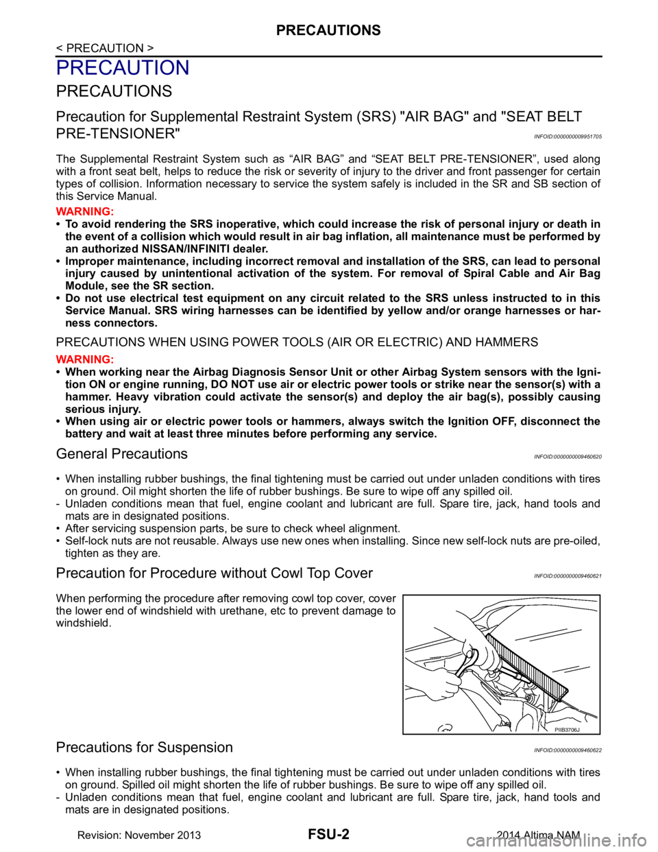
When performing the procedure after removing cowl top cover, cover
the lower end of windshield with urethane, etc to prevent damage to
windshield.
Precautions for SuspensionINFOID:0000000009460622
• When installing rubber bushings, the final tightening mu st be carried out under unladen conditions with tires
on ground. Spilled oil might shorten the life of rubber bushings. Be sure to wipe off any spilled oil.
- Unladen conditions mean that fuel, engine coolant and lubricant are full. Spare tire, jack, hand tools and mats are in designated positions.
PIIB3706J
Revision: November 20132014 Altima NAM
Page 2506 of 4801
PREPARATIONFSU-5
< PREPARATION >
C
D
F
G H
I
J
K L
M A
B
FSU
N
O P
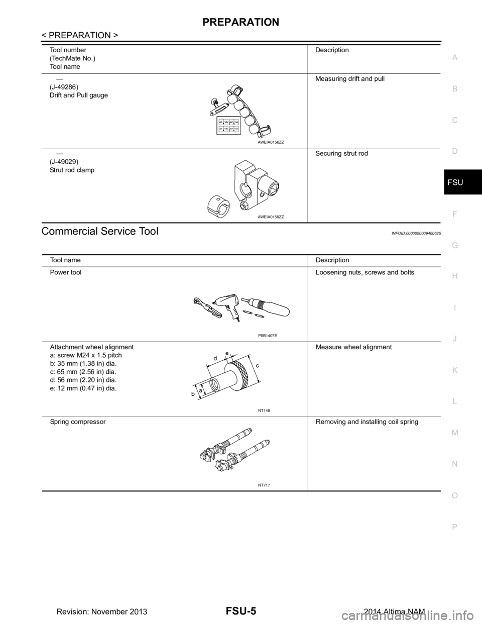
Commercial Service ToolINFOID:0000000009460625
—
(J-49286)
Drift and Pull gauge Measuring drift and pull
—
(J-49029)
Strut rod clamp Securing strut rod
Tool number
(TechMate No.)
Tool name Description
AWEIA0156ZZ
AWEIA0159ZZ
Tool name
Description
Power tool Loosening nuts, screws and bolts
Attachment wheel alignment
a: screw M24 x 1.5 pitch
b: 35 mm (1.38 in) dia.
c: 65 mm (2.56 in) dia.
d: 56 mm (2.20 in) dia.
e: 12 mm (0.47 in) dia. Measure wheel alignment
Spring compressor Removing and installing coil spring
PIIB1407E
NT148
NT717
Revision: November 20132014 Altima NAM
Page 2523 of 4801
FSU-22
< UNIT DISASSEMBLY AND ASSEMBLY >
FRONT COIL SPRING AND STRUT
UNIT DISASSEMBLY AND ASSEMBLY
FRONT COIL SPRING AND STRUT
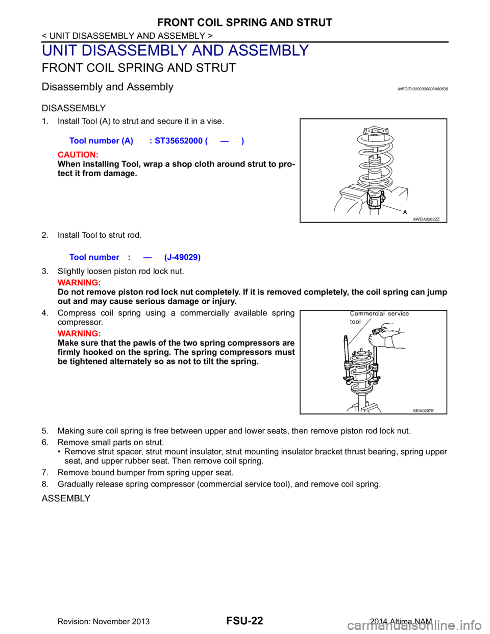
Disassembly and AssemblyINFOID:0000000009460638
DISASSEMBLY
1. Install Tool (A) to strut and secure it in a vise.CAUTION:
When installing Tool, wrap a sh op cloth around strut to pro-
tect it from damage.
2. Install Tool to strut rod.
3. Slightly loosen piston rod lock nut. WARNING:
Do not remove piston rod lock nut completely. If it is removed completely, the coil spring can jump
out and may cause serious damage or injury.
4. Compress coil spring using a commercially available spring compressor.
WARNING:
Make sure that the pawls of the two spring compressors are
firmly hooked on the spring. The spring compressors must
be tightened alternately so as not to tilt the spring.
5. Making sure coil spring is free between upper and lower seats, then remove piston rod lock nut.
6. Remove small parts on strut. • Remove strut spacer, strut mount insulator, strut mounting insulator bracket thrust bearing, spring upper
seat, and upper rubber seat. Then remove coil spring.
7. Remove bound bumper from spring upper seat.
8. Gradually release spring compressor (commercial service tool), and remove coil spring.
ASSEMBLY
Tool number (A) : ST35652000 ( — )
AWEIA0262ZZ
Tool number : — (J-49029)
SEIA0297E
Revision: November 20132014 Altima NAM
Page 2524 of 4801
FRONT COIL SPRING AND STRUTFSU-23
< UNIT DISASSEMBLY AND ASSEMBLY >
C
D
F
G H
I
J
K L
M A
B
FSU
N
O P
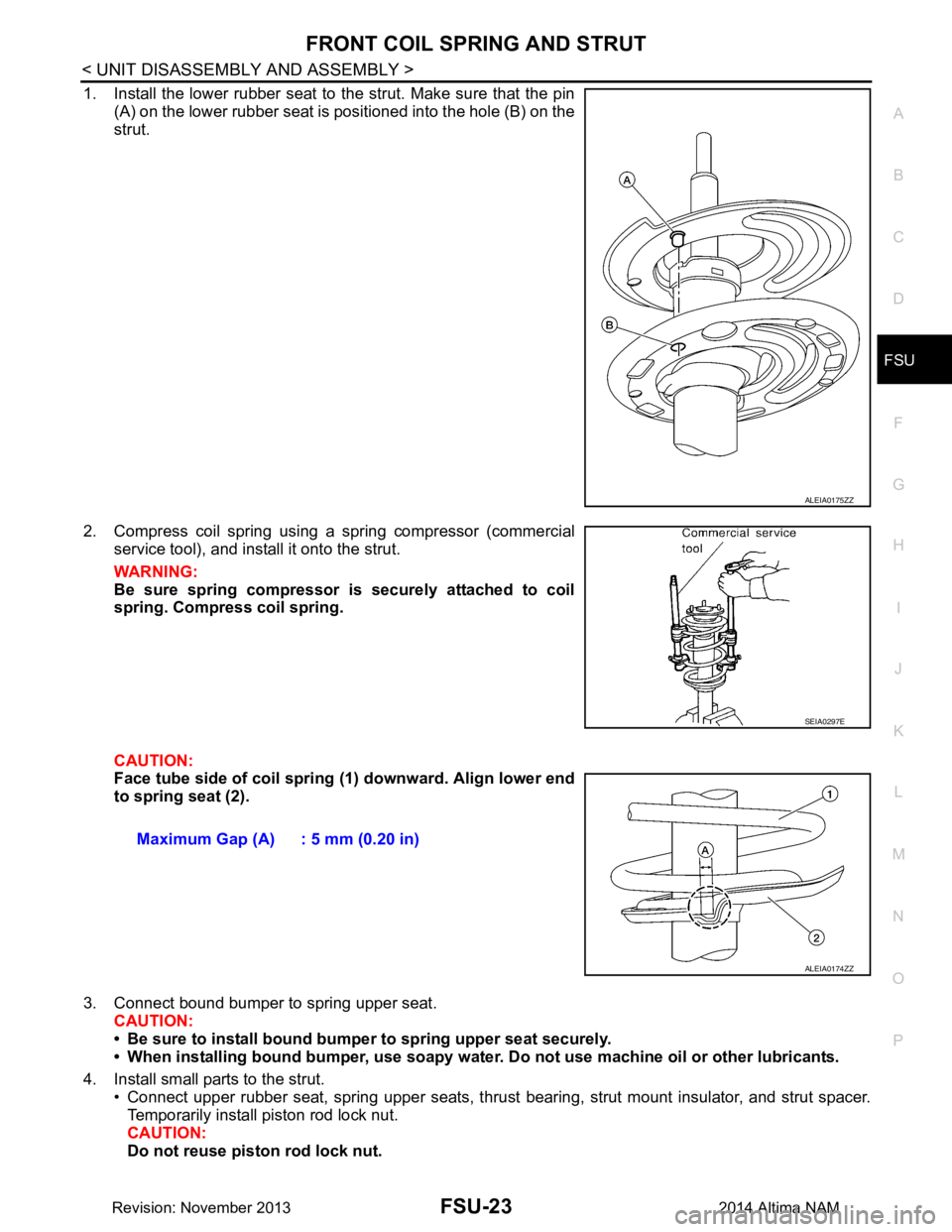
1. Install the lower rubber seat to the strut. Make sure that the pin (A) on the lower rubber seat is positioned into the hole (B) on the
strut.
2. Compress coil spring using a spring compressor (commercial service tool), and install it onto the strut.
WARNING:
Be sure spring compressor is securely attached to coil
spring. Compress coil spring.
CAUTION:
Face tube side of coil spring (1) downward. Align lower end
to spring seat (2).
3. Connect bound bumper to spring upper seat. CAUTION:
• Be sure to install bound bump er to spring upper seat securely.
• When installing bound bumper, use soapy water. Do not use machine oil or other lubricants.
4. Install small parts to the strut. • Connect upper rubber seat, spring upper seats, thrust bearing, strut mount insulator, and strut spacer.
Temporarily install piston rod lock nut.
CAUTION:
Do not reuse piston rod lock nut.
ALEIA0175ZZ
SEIA0297E
Maximum Gap (A) : 5 mm (0.20 in)
ALEIA0174ZZ
Revision: November 20132014 Altima NAM
Page 2529 of 4801
GI-1
GENERAL INFORMATION
C
D E
F
G H
I
J
K L
M B
GI
SECTION GI
N
O P
CONTENTS
GENERAL INFORMATION
HOW TO USE THIS MANU AL ......................3
HOW TO USE THIS MANUAL ....................... .....3
Description .......................................................... ......3
Terms ........................................................................3
Units ..........................................................................3
Contents ....................................................................3
Relation between Illustrations and Descriptions .......4
Components ..............................................................4
HOW TO FOLLOW TROUBLE DIAGNOSES .....6
Description ................................................................6
How to Follow Test Groups in Trouble Diagnosis ......6
Key to Symbols Signifying Measurements or Pro-
cedures ............................................................... ......
7
HOW TO READ WIRING DIAGRAMS ................9
Connector symbols ............................................. ......9
Sample/wiring diagram -example- ...........................10
Description ..............................................................11
ABBREVIATIONS .......................................... ....13
Abbreviation List .................................................. ....13
TIGHTENING TORQUE OF STANDARD
BOLTS ............................................................ ....
18
Description .......................................................... ....18
Tightening Torque Table (New Standard Includ-
ed) ....................................................................... ....
18
RECOMMENDED CHEMICAL PRODUCTS
AND SEALANTS ............................................ ....
21
Recommended Chemical Products and Sealants ....21
VEHICLE INFORMATION ............................22
IDENTIFICATION INFORMATION ................. ....22
Model Variation ................................................... ....22
Identification Number ..............................................23
Identification Plate ...................................................24
Engine Serial Number .............................................24
CVT Number ...........................................................25
Dimensions .......................................................... ....25
Wheels & Tires ........................................................25
PRECAUTION ..............................................26
PRECAUTIONS .................................................26
Description ........................................................... ....26
Precaution for Supplemental Restraint System
(SRS) "AIR BAG" and "SEAT BELT PRE-TEN-
SIONER" ............................................................. ....
26
Precautions For Xenon Headlamp Service .............26
Procedures without Cowl Top Cover .......................27
Cautions in Removing Battery Terminal and AV
Control Unit .......................................................... ....
27
General Precautions ................................................27
Three Way Catalyst .................................................29
Fuel (Regular Unleaded Gasoline Recommend-
ed) QR25DE ........................................................ ....
29
Fuel (Regular Unleaded Gasoline Recommend-
ed) VQ35DE ........................................................ ....
29
Multiport Fuel Injection System or Engine Control
System ................................................................. ....
29
Hoses ......................................................................29
Engine Oils ..............................................................30
Air Conditioning .......................................................31
LIFTING POINT .................................................32
Special Service Tool ................................................32
Pantograph Jack ......................................................32
Garage Jack and Safety Stand ................................33
2-Pole Lift ................................................................34
Board-on Lift ............................................................35
TOW TRUCK TOWING .....................................36
Tow Truck Towing ...................................................36
Vehicle Recovery (Freeing a Stuck Vehicle) ...........36
WIRING DIAGRAM ......................................38
CONSULT CHECKING SYSTEM .....................38
Wiring Diagram .................................................... ....38
Revision: November 20132014 Altima NAMRevision: November 20132014 Altima NAM