2014 NISSAN TEANA SEC
[x] Cancel search: SECPage 2289 of 4801
DIAGNOSIS SYSTEM (IPDM E/R)EXL-23
< SYSTEM DESCRIPTION >
C
D E
F
G H
I
J
K
M A
B
EXL
N
O P
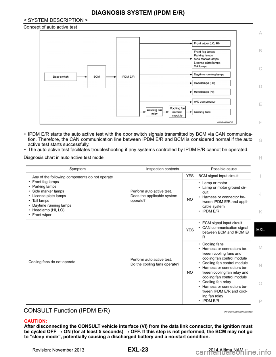
Concept of auto active test
• IPDM E/R starts the auto active test with the door
switch signals transmitted by BCM via CAN communica-
tion. Therefore, the CAN communication line between IPDM E/R and BCM is considered normal if the auto
active test starts successfully.
• The auto active test facilitates troubleshooting if any systems controlled by IPDM E/R cannot be operated.
Diagnosis chart in auto active test mode
CONSULT Function (IPDM E/R)INFOID:0000000009956488
CAUTION:
After disconnecting the CONSULT vehicle interface (VI) from the data link connector, the ignition must
be cycled OFF → ON (for at least 5 seconds) → OFF. If this step is not performed, the BCM may not go
to ”sleep mode”, potentiall y causing a discharged battery and a no-start condition.
AWMIA1280GB
Symptom Inspection contents Possible cause
Any of the following components do not operate
• Front fog lamps
•Parking lamps
• Side marker lamps
• License plate lamps
•Tail lamps
• Daytime running lamps
• Headlamp (HI, LO)
• Front wiper Perform auto active test.
Does the applicable system
operate? YES BCM signal input circuit
NO • Lamp or motor
• Lamp or motor ground cir-
cuit
• Harness or connector be- tween IPDM E/R and appli-
cable system
• IPDM E/R
Cooling fans do not operate Perform auto active test.
Do the cooling fans operate? YES
• ECM signal input circuit
• CAN communication signal between ECM and IPDM E/
R
NO • Cooling fans
• Harness or connectors be-
tween cooling fans and
cooling fan control module
• Cooling fan control module
• Harness or connectors be- tween cooling fan relay and
cooling fan control module
• Cooling fan relay
• Harness or connectors be- tween IPDM E/R and cool-
ing fan relay
• IPDM E/R
Revision: November 20132014 Altima NAMRevision: November 20132014 Altima NAM
Page 2357 of 4801
HEADLAMP (HI) CIRCUITEXL-91
< DTC/CIRCUIT DIAGNOSIS >
C
D E
F
G H
I
J
K
M A
B
EXL
N
O P
HEADLAMP (HI) CIRCUIT
DescriptionINFOID:0000000009463577
The IPDM E/R (intelligent power distribution modul e engine room) controls the headlamp high relay based on
inputs from the BCM over the CAN communication li nes. When the headlamp high relay is energized, power
flows through fuses 34 and 35, located in the IPDM E/R. Power then flows to the front combination lamps to
the headlamp high beam.
Component Function CheckINFOID:0000000009463578
1.CHECK HEADLAMP (HI) OPERATION
WITHOUT CONSULT
1. Start IPDM E/R auto active test. Refer to PCS-8, "Diagnosis Description"
.
2. Check that the headlamp switches to the high beam. NOTE:
HI/LO is repeated 1 second each when using the IPDM E/R auto active test.
CONSULT
1. Select EXTERNAL LAMP of IP DM E/R active test item.
2. While operating the test items, check t hat the headlamp switches to the high beam.
Is the inspection result normal?
YES >> Headlamp (HI) circuit is normal.
NO >> Refer to EXL-91, "Diagnosis Procedure"
.
Diagnosis ProcedureINFOID:0000000009463579
Regarding Wiring Diagram information, refer to EXL-27, "Wiring Diagram - Halogen" or EXL-33, "Wiring Dia-
gram - Xenon".
1.CHECK HEADLAMP (HI) FUSES
1. Turn the ignition switch OFF.
2. Check that the following fuses are not blown.
Is the fuse blown?
YES >> Replace the fuse after repairing the affected circuit.
NO >> GO TO 2.
2.CHECK HEADLAMP (HI) OUTPUT VOLTAGE
CONSULT ACTIVE TEST
1. Turn the ignition switch OFF.
2. Disconnect the front combination lamp harness connector E213 or E222 in question.
3. Turn the ignition switch ON.
4. Select EXTERNAL LAMP of IP DM E/R active test item.
5. With EXTERNAL LAMP ON, check the voltage between the combination lamp connector and ground.
HI : Headlamp switches to the high beam.
OFF : Headlamp OFF
Unit Location Fuse No. Capacity
Headlamp HI (LH) IPDM E/R 35 10A
Headlamp HI (RH) IPDM E/R 34 10A
Revision: November 20132014 Altima NAMRevision: November 20132014 Altima NAM
Page 2359 of 4801
HEADLAMP (LO) CIRCUITEXL-93
< DTC/CIRCUIT DIAGNOSIS >
C
D E
F
G H
I
J
K
M A
B
EXL
N
O P
HEADLAMP (LO) CIRCUIT
HEADLAMP (HALOGEN)
HEADLAMP (HALOGEN) : DescriptionINFOID:0000000009463580
The IPDM E/R (intelligent power distribution modul e engine room) controls the headlamp low relay based on
inputs from the BCM over the CAN communication li nes. When the headlamp low relay is energized, power
flows through fuses 36 and 37, located in the IPDM E/R. Power then flows to the front combination lamps to
the headlamp low beam.
HEADLAMP (HALOGEN) : Component Function CheckINFOID:0000000009463581
1.CHECK HEADLAMP (LO) OPERATION
WITHOUT CONSULT
1. Start IPDM E/R auto active test. Refer to PCS-8, "Diagnosis Description"
.
2. Check that the headlamp is turned ON.
NOTE:
HI/LO is repeated 1 second each when using the IPDM E/R auto active test.
CONSULT
1. Select EXTERNAL LAMP of IP DM E/R active test item.
2. While operating the test items, check that the headlamp is turned ON.
Is the inspection result normal?
YES >> Headlamp (LO) is normal.
NO >> Refer to EXL-93, "HEADLAMP (HALOGEN) : Diagnosis Procedure"
.
HEADLAMP (HALOGEN) : Diagnosis ProcedureINFOID:0000000009463582
Regarding Wiring Diagram information, refer to EXL-27, "Wiring Diagram - Halogen".
1.CHECK HEADLAMP (LO) FUSES
1. Turn the ignition switch OFF.
2. Check that the following fuses are not blown.
Is the fuse blown?
YES >> Replace the fuse after repairing the affected circuit.
NO >> GO TO 2.
2.CHECK HEADLAMP (LO) OUTPUT VOLTAGE
CONSULT
1. Turn the ignition switch OFF.
2. Disconnect the front combination lamp harness connector E212 or E223 in question.
3. Turn the ignition switch ON.
4. Select EXTERNAL LAMP of IP DM E/R active test item.
5. With EXTERNAL LAMP ON, check the voltage betw een the combination lamp connector E212 or E223
terminal 1 and ground. LO : Headlamp ON
OFF : Headlamp OFF
Unit Location Fuse No. Capacity
Headlamp LO (RH) IPDM E/R 36 15A
Headlamp LO (L H) IPDM E/R 37 15A
Revision: November 20132014 Altima NAMRevision: November 20132014 Altima NAM
Page 2360 of 4801
EXL-94
< DTC/CIRCUIT DIAGNOSIS >
HEADLAMP (LO) CIRCUIT
Is the inspection result normal?
YES >> GO TO 4.
NO >> GO TO 3.
3.CHECK HEADLAMP (LO) CIRCUIT FOR OPEN
1. Turn the ignition switch OFF.
2. Disconnect IPDM E/R connector E200.
3. Check continuity between the IPDM E/R harness c onnector E200 and the front combination lamp harness
connector E223 or E212.
Is the inspection result normal?
YES >> Replace IPDM E/R. Refer to PCS-32, "Removal and Installation".
NO >> Repair or replace the harness or connector.
4.CHECK FRONT COMBINATION LAMP (LO) GROUND CIRCUIT
Check continuity between the front combination la mp harness connector E223 or E212 terminal 2 and ground.
Is the inspection result normal?
YES >> Inspect the headlamp bulb.
NO >> Repair or replace the harness or connector.
HEADLAMP (XENON)
HEADLAMP (XENON) : DescriptionINFOID:0000000009463583
The IPDM E/R (intelligent power distribution modul e engine room) controls the headlamp low relay based on
inputs from the BCM over the CAN communication li nes. When the headlamp low relay is energized, power
flows through fuses 36 and 37, located in the IPDM E/R. Power then flows to the front combination lamps to
the headlamp low beam.
HEADLAMP (XENON) : Component Function CheckINFOID:0000000009463584
1.CHECK HEADLAMP (LO) OPERATION
WITHOUT CONSULT
1. Start IPDM E/R auto active test. Refer to PCS-8, "Diagnosis Description"
.
2. Check that the headlamp is turned ON. NOTE:
HI/LO is repeated 1 second each when usi ng the IPDM E/R auto active test.
CONSULT
1. Select EXTERNAL LAMP of IP DM E/R active test item.
2. While operating the test items, c heck that the headlamp is turned ON.
(+)
(− )Voltage
Connector Terminal
RH E223 1 Ground Battery voltage
LH E212
IPDM E/R Front combination lamp Continuity
Connector Terminal Connector Terminal
RH E20075 E223
1Yes
LH 76 E212
Connector Terminal — Continuity
RH E223 2GroundYes
LH E212
Revision: November 20132014 Altima NAMRevision: November 20132014 Altima NAM
Page 2393 of 4801
FRONT COMBINATION LAMPEXL-127
< REMOVAL AND INSTALLATION >
C
D E
F
G H
I
J
K
M A
B
EXL
N
O P
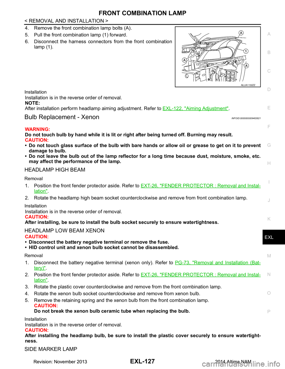
4. Remove the front combination lamp bolts (A).
5. Pull the front combination lamp (1) forward.
6. Disconnect the harness connectors from the front combination
lamp (1).
Installation
Installation is in the reverse order of removal.
NOTE:
After installation perform headlamp aiming adjustment. Refer to EXL-122, "Aiming Adjustment"
.
Bulb Replacement - XenonINFOID:0000000009463621
WARNING:
Do not touch bulb by hand while it is lit or right after being turned off. Burning may result.
CAUTION:
• Do not touch glass surface of the bulb with bare hand s or allow oil or grease to get on it to prevent
damage to bulb.
• Do not leave the bulb out of the lamp reflector fo r a long time because dust, moisture, smoke, etc.
may affect the performance of the lamp.
HEADLAMP HIGH BEAM
Removal
1. Position the front fender pr otector aside. Refer to EXT-26, "FENDER PROTECTOR : Removal and Instal-
lation".
2. Rotate the headlamp high beam socket countercloc kwise and remove from front combination lamp.
Installation
Installation is in the reverse order of removal.
CAUTION:
After installing, be sure to install the bulb socket securely to ensure watertightness.
HEADLAMP LOW BEAM XENON
CAUTION:
• Disconnect the battery negative terminal or remove the fuse.
• HID control unit and xenon bu lb socket cannot be disassembled.
Removal
1. Disconnect the battery negative te rminal (xenon only). Refer to PG-73, "Removal and Installation (Bat-
tery)".
2. Position the front fender pr otector aside. Refer to EXT-26, "FENDER PROTECTOR : Removal and Instal-
lation".
3. Rotate the plastic cover counterclockwise and remove from the front combination lamp.
4. Rotate the xenon bulb socket counterclockwise and remove from xenon bulb.
5. Remove the retaining spring and the xenon bulb from the front combination lamp. CAUTION:
Do not break the xenon bulb ceramic tube when replacing the bulb.
Installation
Installation is in the reverse order of removal.
CAUTION:
After installing the headlamp bulb, be sure to inst all the plastic cover securely to ensure watertight-
ness.
SIDE MARKER LAMP
ALLIA1132ZZ
Revision: November 20132014 Altima NAMRevision: November 20132014 Altima NAM
Page 2394 of 4801
EXL-128
< REMOVAL AND INSTALLATION >
FRONT COMBINATION LAMP
Removal
1. Position the front fender protector aside. Refer to EXT-26, "FENDER PROTECTOR : Removal and Instal-
lation".
2. Rotate the side marker lamp bulb socket counterclockwise and remove.
3. Remove the side marker bulb from the front combination lamp.
Installation
Installation is in the reverse order of removal.
CAUTION:
After installing, be sure to install the bu lb socket securely to ensure watertightness.
Exploded View - HalogenINFOID:0000000009463622
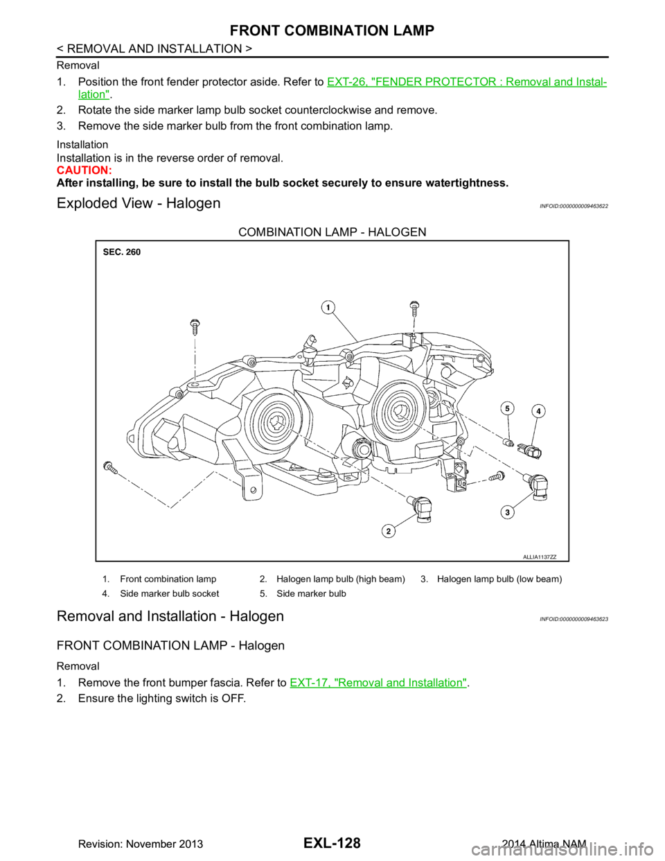
COMBINATION LAMP - HALOGEN
Removal and Installation - HalogenINFOID:0000000009463623
FRONT COMBINATION LAMP - Halogen
Removal
1. Remove the front bumper fascia. Refer to EXT-17, "Removal and Installation".
2. Ensure the lighting switch is OFF.
ALLIA1137ZZ
1. Front combination lamp 2. Halogen lamp bulb (high beam) 3. Halogen lamp bulb (low beam)
4. Side marker bulb socket 5. Side marker bulb
Revision: November 20132014 Altima NAMRevision: November 20132014 Altima NAM
Page 2395 of 4801
FRONT COMBINATION LAMPEXL-129
< REMOVAL AND INSTALLATION >
C
D E
F
G H
I
J
K
M A
B
EXL
N
O P
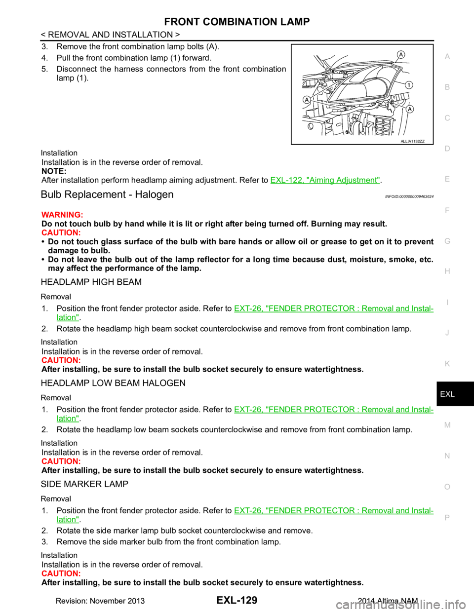
3. Remove the front combination lamp bolts (A).
4. Pull the front combination lamp (1) forward.
5. Disconnect the harness connectors from the front combination
lamp (1).
Installation
Installation is in the reverse order of removal.
NOTE:
After installation perform headlamp aiming adjustment. Refer to EXL-122, "Aiming Adjustment"
.
Bulb Replacement - HalogenINFOID:0000000009463624
WARNING:
Do not touch bulb by hand while it is lit or right after being turned off. Burning may result.
CAUTION:
• Do not touch glass surface of the bulb with bare hand s or allow oil or grease to get on it to prevent
damage to bulb.
• Do not leave the bulb out of the lamp reflector fo r a long time because dust, moisture, smoke, etc.
may affect the performance of the lamp.
HEADLAMP HIGH BEAM
Removal
1. Position the front fender pr otector aside. Refer to EXT-26, "FENDER PROTECTOR : Removal and Instal-
lation".
2. Rotate the headlamp high beam socket countercloc kwise and remove from front combination lamp.
Installation
Installation is in the reverse order of removal.
CAUTION:
After installing, be sure to install the bulb socket securely to ensure watertightness.
HEADLAMP LOW BEAM HALOGEN
Removal
1. Position the front fender protector aside. Refer to EXT-26, "FENDER PROTECTOR : Removal and Instal-
lation".
2. Rotate the headlamp low beam sockets countercloc kwise and remove from front combination lamp.
Installation
Installation is in the reverse order of removal.
CAUTION:
After installing, be sure to install the bulb socket securely to ensure watertightness.
SIDE MARKER LAMP
Removal
1. Position the front fender protector aside. Refer to EXT-26, "FENDER PROTECTOR : Removal and Instal-
lation".
2. Rotate the side marker lamp bulb socket counterclockwise and remove.
3. Remove the side marker bulb from the front combination lamp.
Installation
Installation is in the reverse order of removal.
CAUTION:
After installing, be sure to install the bulb socket securely to ensure watertightness.
ALLIA1132ZZ
Revision: November 20132014 Altima NAMRevision: November 20132014 Altima NAM
Page 2396 of 4801
EXL-130
< REMOVAL AND INSTALLATION >
TURN SIGNAL AND HAZARD WARNING LAMPS
TURN SIGNAL AND HAZARD WARNING LAMPS
Removal and InstallationINFOID:0000000009463625
REMOVAL
1. Remove the front fender protector side cover.
2. Position the fender protector aside. Refer to EXT-26, "FENDER PROTECTOR : Removal and Installa-
tion".
3. Disconnect the harness connector from the turn signal and hazard warning lamp.
4. Remove front fog lamp finisher. Refer to EXT-17, "Removal and Installation"
.
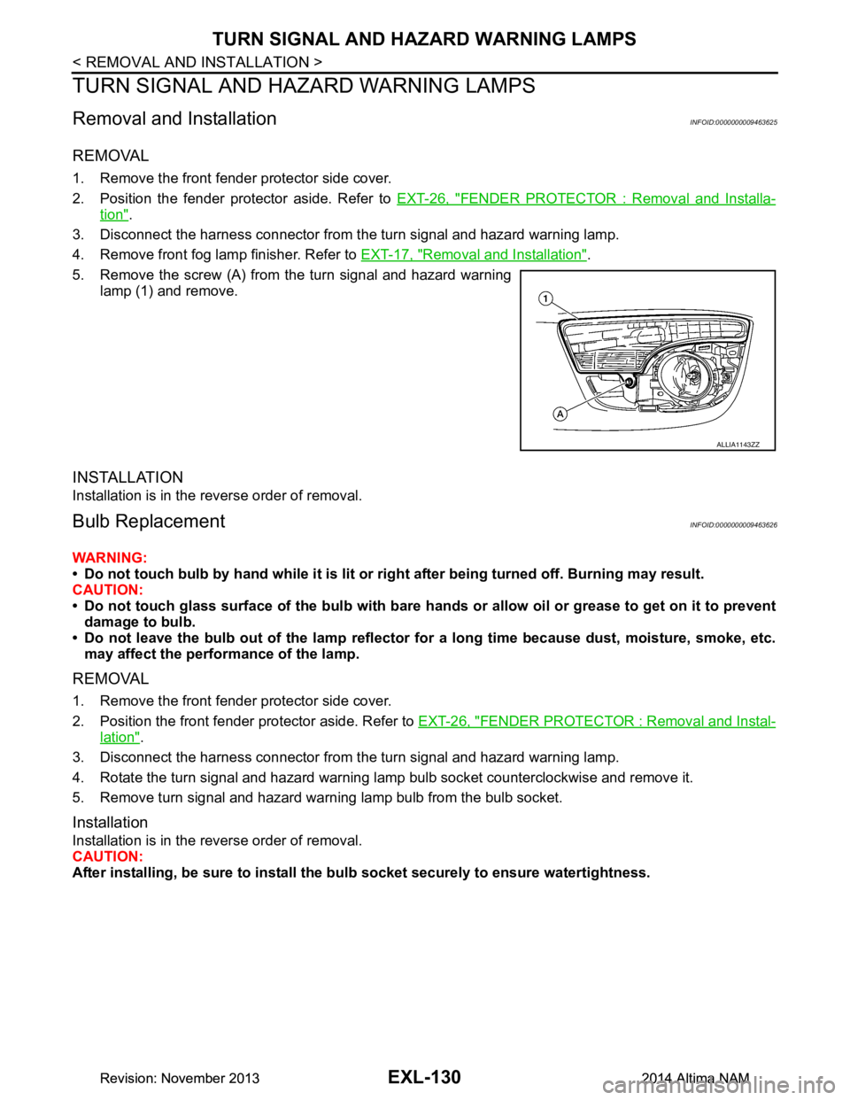
5. Remove the screw (A) from the turn signal and hazard warning lamp (1) and remove.
INSTALLATION
Installation is in the reverse order of removal.
Bulb ReplacementINFOID:0000000009463626
WARNING:
• Do not touch bulb by hand while it is lit or right after being turned off. Burning may result.
CAUTION:
• Do not touch glass surface of the bulb with bare hands or allow oil or grease to get on it to prevent
damage to bulb.
• Do not leave the bulb out of the lamp reflector fo r a long time because dust, moisture, smoke, etc.
may affect the performance of the lamp.
REMOVAL
1. Remove the front fender protector side cover.
2. Position the front fender protector aside. Refer to EXT-26, "FENDER PROTECTOR : Removal and Instal-
lation".
3. Disconnect the harness connector from the turn signal and hazard warning lamp.
4. Rotate the turn signal and hazard warning lamp bulb socket counterclockwise and remove it.
5. Remove turn signal and hazard warning lamp bulb from the bulb socket.
Installation
Installation is in the reverse order of removal.
CAUTION:
After installing, be sure to install the bu lb socket securely to ensure watertightness.
ALLIA1143ZZ
Revision: November 20132014 Altima NAMRevision: November 20132014 Altima NAM