2014 NISSAN TEANA change time
[x] Cancel search: change timePage 2131 of 4801
![NISSAN TEANA 2014 Service Manual
SPARK PLUGEM-133
< PERIODIC MAINTENANCE > [VQ35DE]
C
D E
F
G H
I
J
K L
M A
EM
NP
O
• Do not use a wire brush for cleaning the spark plugs. Replace as
necessary.
• If plug is covered with carbon NISSAN TEANA 2014 Service Manual
SPARK PLUGEM-133
< PERIODIC MAINTENANCE > [VQ35DE]
C
D E
F
G H
I
J
K L
M A
EM
NP
O
• Do not use a wire brush for cleaning the spark plugs. Replace as
necessary.
• If plug is covered with carbon](/manual-img/5/57390/w960_57390-2130.png)
SPARK PLUGEM-133
< PERIODIC MAINTENANCE > [VQ35DE]
C
D E
F
G H
I
J
K L
M A
EM
NP
O
• Do not use a wire brush for cleaning the spark plugs. Replace as
necessary.
• If plug is covered with carbon, a spark plug cleaner may be used.
• Checking and adjusting plug gap is not required between change intervals. If the gap is out of s pecification, replace the spark plug.
INSTALLATION
Installation is in the reverse order of removal.
*: Always check with the Parts Department for the latest parts information.
SMA773C
Cleaner air pressure : less than 588 kPa (6 kg/cm2, 85 psi)
Cleaning time : less than 20 seconds
SMA806CA
Standard type* DENSO
FXE22HR11
Gap (nominal) 1.1 mm (0.043 in)
Revision: November 20132014 Altima NAM
Page 2276 of 4801
EXL-10
< SYSTEM DESCRIPTION >
SYSTEM
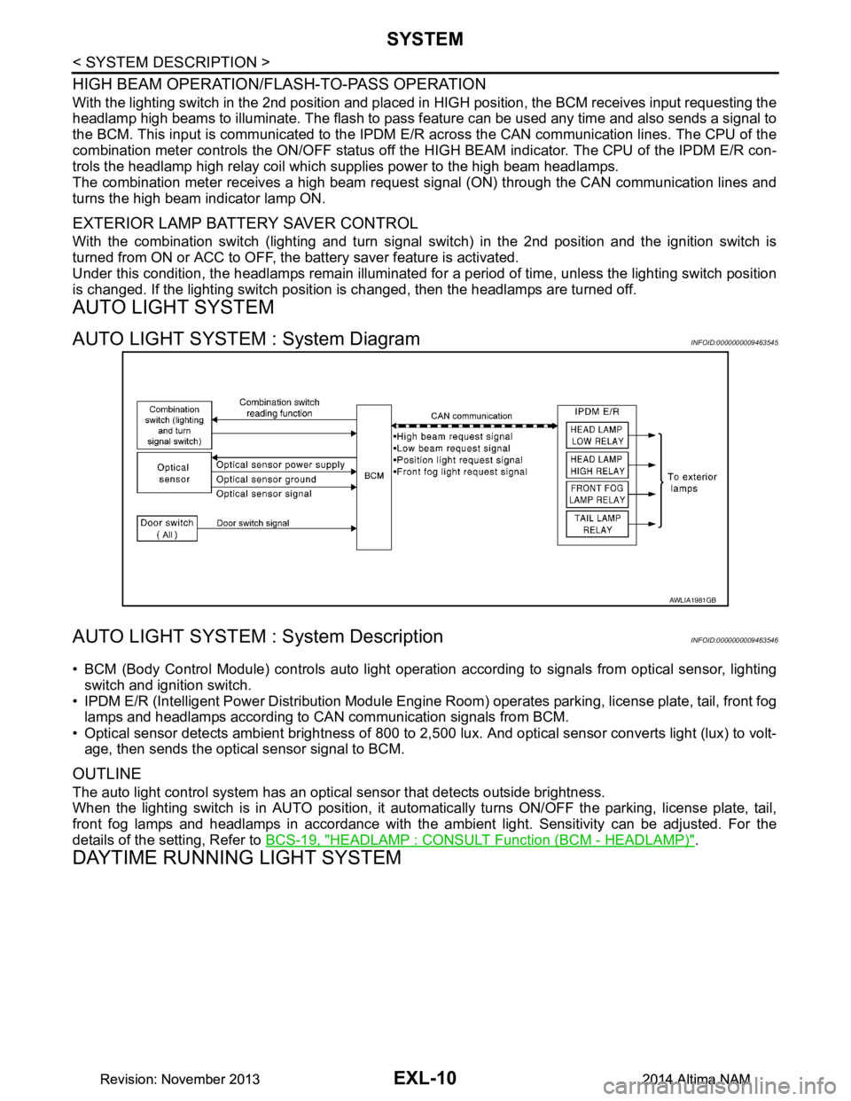
HIGH BEAM OPERATION/FLASH-TO-PASS OPERATION
With the lighting switch in the 2nd position and placed in HIGH position, the BCM receives input requesting the
headlamp high beams to illuminate. The flash to pass f eature can be used any time and also sends a signal to
the BCM. This input is communicated to the IPDM E/R across the CAN communication lines. The CPU of the
combination meter controls the ON/OFF status off the HIGH BEAM indicator. The CPU of the IPDM E/R con-
trols the headlamp high relay coil which supplies power to the high beam headlamps.
The combination meter receives a high beam request signal (ON) through the CAN communication lines and
turns the high beam indicator lamp ON.
EXTERIOR LAMP BATTERY SAVER CONTROL
With the combination switch (lighting and turn signal switch) in the 2nd position and the ignition switch is
turned from ON or ACC to OFF, the battery saver feature is activated.
Under this condition, the headlamps remain illuminated fo r a period of time, unless the lighting switch position
is changed. If the lighting switch position is changed, then the headlamps are turned off.
AUTO LIGHT SYSTEM
AUTO LIGHT SYSTEM : System DiagramINFOID:0000000009463545
AUTO LIGHT SYSTEM : System DescriptionINFOID:0000000009463546
• BCM (Body Control Module) controls auto light operati on according to signals from optical sensor, lighting
switch and ignition switch.
• IPDM E/R (Intelligent Power Distribution Module Engine R oom) operates parking, license plate, tail, front fog
lamps and headlamps according to CAN communication signals from BCM.
• Optical sensor detects ambient brightness of 800 to 2,500 lux. And optical sensor converts light (lux) to volt-
age, then sends the optical sensor signal to BCM.
OUTLINE
The auto light control system has an optical sensor that detects outside brightness.
When the lighting switch is in AUTO position, it autom atically turns ON/OFF the parking, license plate, tail,
front fog lamps and headlamps in accordance with the am bient light. Sensitivity can be adjusted. For the
details of the setting, Refer to BCS-19, "HEADLAMP : CONSULT Function (BCM - HEADLAMP)"
.
DAYTIME RUNNING LIGHT SYSTEM
AWLIA1981GB
Revision: November 20132014 Altima NAMRevision: November 20132014 Altima NAM
Page 2278 of 4801
EXL-12
< SYSTEM DESCRIPTION >
SYSTEM
TURN SIGNAL AND HAZARD WARNI NG LAMPS : System Diagram
INFOID:0000000009463551
TURN SIGNAL AND HAZARD WARNING LAMPS : System DescriptionINFOID:0000000009463552
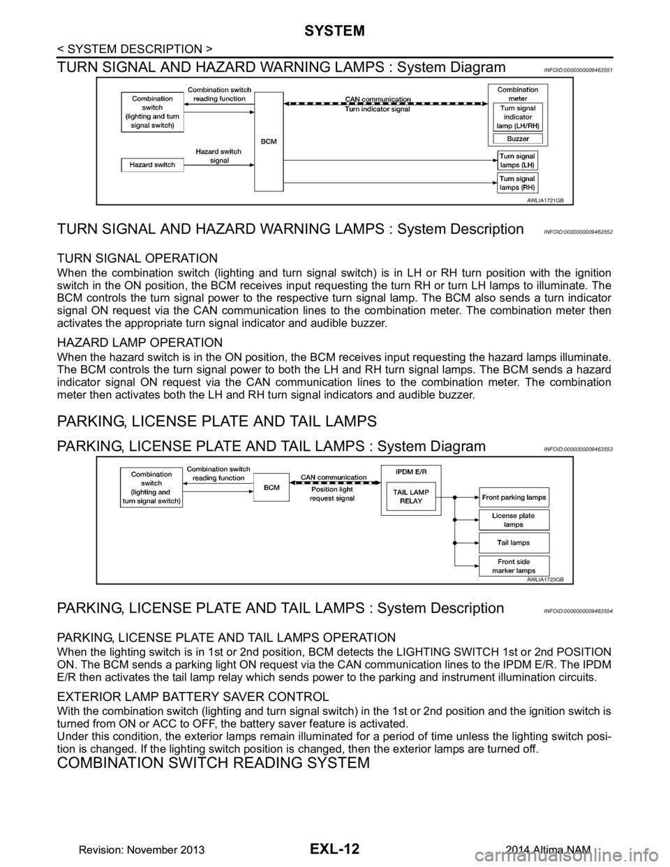
TURN SIGNAL OPERATION
When the combination switch (lighting and turn signal swit ch) is in LH or RH turn position with the ignition
switch in the ON position, the BCM receives input reques ting the turn RH or turn LH lamps to illuminate. The
BCM controls the turn signal power to the respective turn signal lamp. The BCM also sends a turn indicator
signal ON request via the CAN communication lines to the combination meter. The combination meter then
activates the appropriate turn signal indicator and audible buzzer.
HAZARD LAMP OPERATION
When the hazard switch is in the ON position, the BC M receives input requesting the hazard lamps illuminate.
The BCM controls the turn signal power to both the LH and RH turn signal lamps. The BCM sends a hazard
indicator signal ON request via the CAN communication lines to the combination meter. The combination
meter then activates both the LH and RH turn signal indicators and audible buzzer.
PARKING, LICENSE PLATE AND TAIL LAMPS
PARKING, LICENSE PLATE AND TAIL LAMPS : System DiagramINFOID:0000000009463553
PARKING, LICENSE PLATE AND TA IL LAMPS : System DescriptionINFOID:0000000009463554
PARKING, LICENSE PLATE AND TAIL LAMPS OPERATION
When the lighting switch is in 1st or 2nd position, BCM detects the LIGHTING SWITCH 1st or 2nd POSITION
ON. The BCM sends a parking light ON request via the CAN communication lines to the IPDM E/R. The IPDM
E/R then activates the tail lamp relay which sends power to the parking and instrument illumination circuits.
EXTERIOR LAMP BATTERY SAVER CONTROL
With the combination switch (lighting and turn signal switch) in the 1st or 2nd position and the ignition switch is
turned from ON or ACC to OFF, the battery saver feature is activated.
Under this condition, the exterior lamps remain illumi nated for a period of time unless the lighting switch posi-
tion is changed. If the lighting switch position is changed, then the exterior lamps are turned off.
COMBINATION SWITCH READING SYSTEM
AWLIA1721GB
AWLIA1723GB
Revision: November 20132014 Altima NAMRevision: November 20132014 Altima NAM
Page 2283 of 4801

DIAGNOSIS SYSTEM (BCM)EXL-17
< SYSTEM DESCRIPTION >
C
D E
F
G H
I
J
K
M A
B
EXL
N
O P
DIAGNOSIS SYSTEM (BCM)
COMMON ITEM
COMMON ITEM : CONSULT Function (BCM - COMMON ITEM)INFOID:0000000009956424
CAUTION:
After disconnecting the CONSULT vehicle interface (VI) from the data link connector, the ignition must
be cycled OFF → ON (for at least 5 seconds) → OFF. If this step is not performed, the BCM may not go
to ”sleep mode”, potentiall y causing a discharged battery and a no-start condition.
APPLICATION ITEM
CONSULT performs the following functions via CAN communication with BCM.
SYSTEM APPLICATION
BCM can perform the following functions.
Direct Diagnostic Mode Description
Ecu Identification The BCM part number is displayed.
Self Diagnostic Result The BCM self diagnostic results are displayed.
Data Monitor The BCM input/output data is displayed in real time.
Active Test The BCM activates outputs to test components.
Work support The settings for BCM functions can be changed.
Configuration • The vehicle specification can be read and saved.
• The vehicle specification can be written when replacing BCM.
CAN Diag Support Mntr The result of transmit/receive diagnosis of CAN communication is displayed.
System Sub System Direct Diagnostic Mode
Ecu Identification
Self Diagnostic Result
Data Monitor
Active Test
Work support
Configuration
CAN Diag Su pport Mntr
Door lock DOOR LOCK ××××
Rear window defogger REAR DEFOGGER ×××
Warning chime BUZZER ××
Interior room lamp timer INT LAMP ×××
Remote keyless entry system MULTI REMOTE ENT ×××
Exterior lamp HEADLAMP ×××
Wiper and washer WIPER ×××
Turn signal and hazard warning lamps FLASHER ××
Air conditioner AIR CONDITIONER ×
Intelligent Key system INTELLIGENT KEY ××××
Combination switch COMB SW ×
BCM BCM × × ×××
Immobilizer IMMU ×××
Interior room lamp battery saver BATTERY SAVER ××
Trunk open TRUNK ×
Vehicle security system THEFT ALM ×××
Revision: November 20132014 Altima NAMRevision: November 20132014 Altima NAM
Page 2427 of 4801

SQUEAK AND RATTLE TROUBLE DIAGNOSESEXT-13
< PERIODIC MAINTENANCE >
C
D E
F
G H
I
J
L
M A
B
EXT
N
O P
1. Loose harness or harness connectors.
2. Front console map/reading lamp lens loose.
3. Loose screws at console attachment points.
SEATS
When isolating seat noise it's important to note the pos ition the seat is in and the load placed on the seat when
the noise is present. These conditions should be duplic ated when verifying and isolating the cause of the
noise.
Cause of seat noise include:
1. Headrest rods and holder
2. A squeak between the seat pad cushion and frame
3. The rear seatback lock and bracket
These noises can be isolated by moving or pressing on the suspected components while duplicating the con-
ditions under which the noise occurs. Most of thes e incidents can be repaired by repositioning the component
or applying urethane tape to the contact area.
UNDERHOOD
Some interior noise may be caused by components under the hood or on the engine wall. The noise is then
transmitted into the passenger compartment.
Causes of transmitted underhood noise include:
1. Any component installed to the engine wall
2. Components that pass through the engine wall
3. Engine wall mounts and connectors
4. Loose radiator installation pins
5. Hood bumpers out of adjustment
6. Hood striker out of adjustment
These noises can be difficult to isolate since they cannot be reached from the interior of the vehicle. The best
method is to secure, move or insulate one component at a time and test drive the vehicle. Also, engine rpm or
load can be changed to isolate the noise. Repairs can usually be made by moving, adjusting, securing, or
insulating the component causing the noise.
Revision: November 20132014 Altima NAM
Page 2560 of 4801
GI-32
< PRECAUTION >
LIFTING POINT
LIFTING POINT
Special Service ToolINFOID:0000000009463003
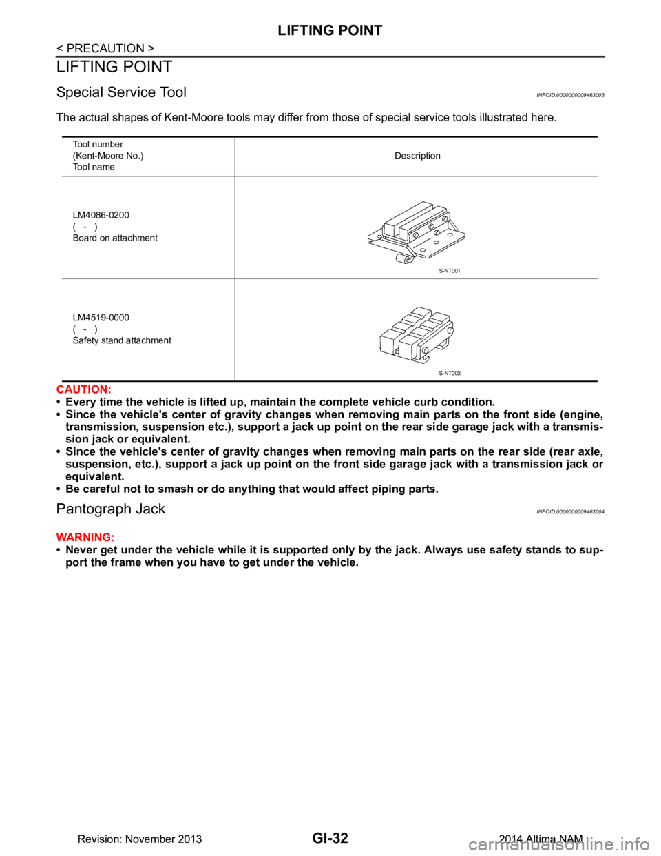
The actual shapes of Kent-Moore tools may differ from those of special service tools illustrated here.
CAUTION:
• Every time the vehicle is lifted up, main tain the complete vehicle curb condition.
• Since the vehicle's center of gravity changes when removing main parts on the front side (engine,
transmission, suspension etc.), supp ort a jack up point on the rear side garage jack with a transmis-
sion jack or equivalent.
• Since the vehicle's center of gravity changes when removing main parts on the rear side (rear axle,
suspension, etc.), support a jack up point on the front side garage jack with a transmission jack or
equivalent.
• Be careful not to smash or do anythi ng that would affect piping parts.
Pantograph JackINFOID:0000000009463004
WARNING:
• Never get under the vehicle while it is supported only by the jack. Always use safety stands to sup-
port the frame when you have to get under the vehicle.
Tool number
(Kent-Moore No.)
Tool name Description
LM4086-0200
( - )
Board on attachment
LM4519-0000
( - )
Safety stand attachment
S-NT001
S-NT002
Revision: November 20132014 Altima NAMRevision: November 20132014 Altima NAM
Page 2574 of 4801
GI-46
< BASIC INSPECTION >
SERVICE INFORMATION FOR ELECTRICAL INCIDENT
Circuit Inspection
INFOID:0000000009463015
DESCRIPTION
• In general, testing electrical circuits is an easy ta sk if it is approached in a logical and organized method.
Before beginning it is important to have all available in formation on the system to be tested. Also, get a thor-
ough understanding of system operation. Then you will be able to use the appropriate equipment and follow
the correct test procedure.
• You may have to simulate vehicle vibrations while te sting electrical components. Gently shake the wiring
harness or electrical component to do this.
NOTE:
Refer to GI-40, "How to Check Terminal"
to probe or check terminal.
TESTING FOR “OPENS” IN THE CIRCUIT
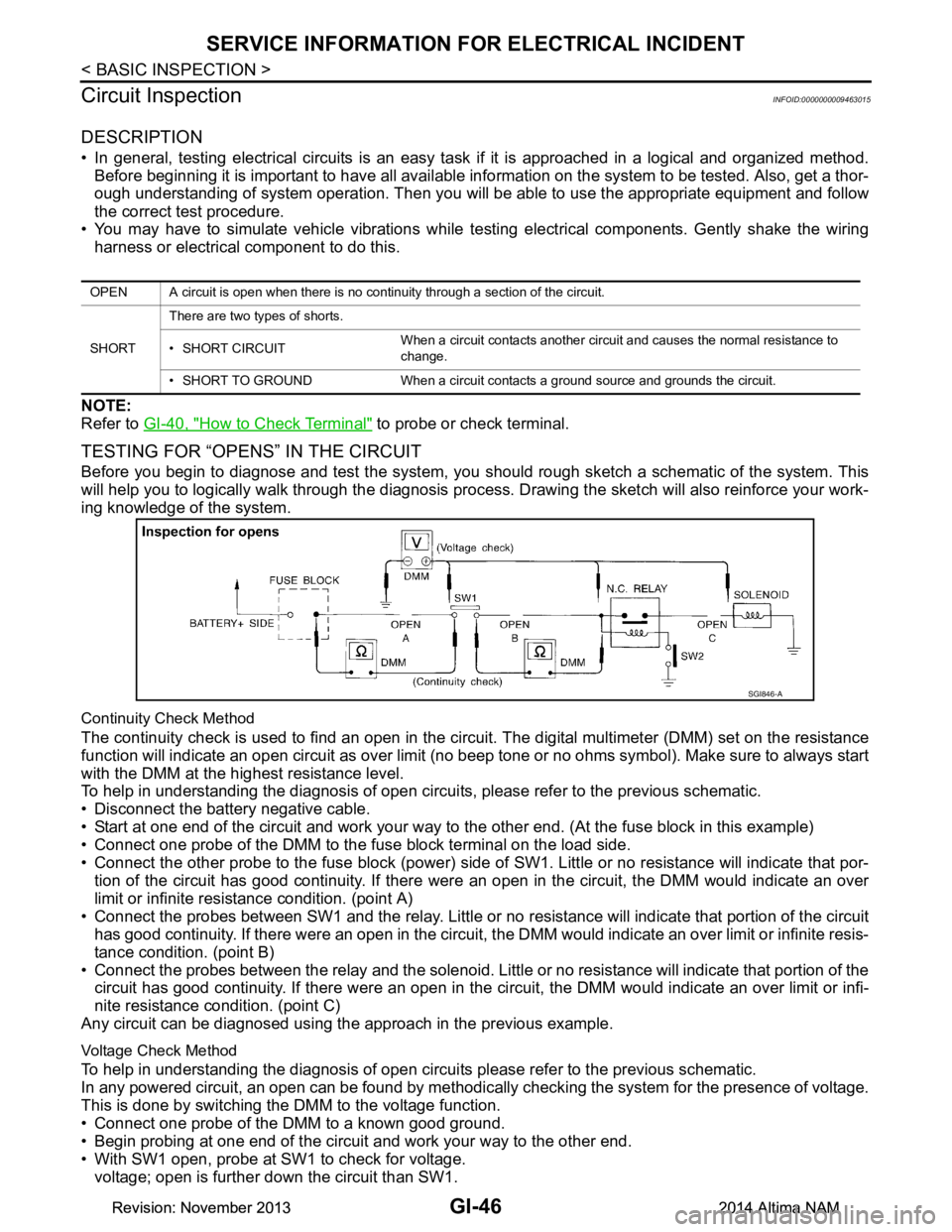
Before you begin to diagnose and test the system, you should rough sketch a schematic of the system. This
will help you to logically walk through the diagnosis process. Drawing the sketch will also reinforce your work-
ing knowledge of the system.
Continuity Check Method
The continuity check is used to find an open in the circ uit. The digital multimeter (DMM) set on the resistance
function will indicate an open circuit as over limit (no beep tone or no ohms symbol). Make sure to always start
with the DMM at the highest resistance level.
To help in understanding the diagnosis of open circui ts, please refer to the previous schematic.
• Disconnect the battery negative cable.
• Start at one end of the circuit and work your way to the other end. (At the fuse block in this example)
• Connect one probe of the DMM to the fuse block terminal on the load side.
• Connect the other probe to the fuse block (power) side of SW1. Little or no resistance will indicate that por-
tion of the circuit has good continuity. If there were an open in the circuit, the DMM would indicate an over
limit or infinite resistance condition. (point A)
• Connect the probes between SW1 and the relay. Little or no resistance will indicate that portion of the circuit
has good continuity. If there were an open in the circuit, t he DMM would indicate an over limit or infinite resis-
tance condition. (point B)
• Connect the probes between the relay and the solenoid. Little or no resistance will indicate that portion of the
circuit has good continuity. If there were an open in the ci rcuit, the DMM would indicate an over limit or infi-
nite resistance condition. (point C)
Any circuit can be diagnosed using the approach in the previous example.
Voltage Check Method
To help in understanding the diagnosis of open circui ts please refer to the previous schematic.
In any powered circuit, an open can be found by methodica lly checking the system for the presence of voltage.
This is done by switching the DMM to the voltage function.
• Connect one probe of the DMM to a known good ground.
• Begin probing at one end of the circuit and work your way to the other end.
• With SW1 open, probe at SW1 to check for voltage. voltage; open is further down the circuit than SW1.
OPEN A circuit is open when there is no continuity through a section of the circuit.
SHORT There are two types of shorts.
• SHORT CIRCUIT When a circuit contacts another circuit and causes the normal resistance to
change.
• SHORT TO GROUND When a circuit contacts a ground source and grounds the circuit.
SGI846-A
Revision: November 20132014 Altima NAMRevision: November 20132014 Altima NAM
Page 2579 of 4801
CONSULT CHECKING SYSTEMGI-51
< BASIC INSPECTION >
C
D E
F
G H
I
J
K L
M B
GI
N
O PCONSULT CHECKING SYSTEM
DescriptionINFOID:0000000009463016
CAUTION:
After disconnecting the CONSULT vehicle interface (VI) from the data link connector, the ignition must
be cycled OFF → ON (for at least 5 seconds) → OFF. If this step is not performed, the BCM may not go
to “sleep mode”, potentiall y causing a discharged battery and a no-start condition.
NOTE:
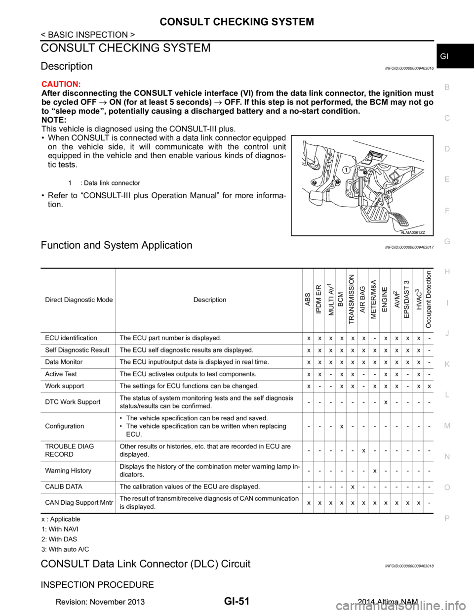
This vehicle is diagnosed using the CONSULT-III plus.
• When CONSULT is connected with a data link connector equipped on the vehicle side, it will communicate with the control unit
equipped in the vehicle and then enable various kinds of diagnos-
tic tests.
• Refer to “CONSULT-III plus Operation Manual” for more informa- tion.
Function and System ApplicationINFOID:0000000009463017
x : Applicable
1: With NAVI
2: With DAS
3: With auto A/C
CONSULT Data Link Connector (DLC) CircuitINFOID:0000000009463018
INSPECTION PROCEDURE
1 : Data link connector
ALAIA0061ZZ
Direct Diagnostic Mode DescriptionABS
IPDM E/R
MULTI AV
1
BCM
TRANSMISSION
AIR BAG
METER/M&A
ENGINE
AV M
2
EPS/DAST 3 HVAC
3
Occupant Detection
ECU identification The ECU part number is displayed. x x x x x x - x x x x -
Self Diagnostic Result The ECU self diagnostic results are displayed. x x x x x x x x x x x -
Data Monitor The ECU input/output data is displayed in real time. x x x x x x x x x x x -
Active Test The ECU activates outputs to test components. x x - x x - - x x - x -
Work support The settings for ECU functions can be changed. x - - x x - x x x - x x
DTC Work Support The status of system monitoring tests and the self diagnosis
status/results can be confirmed. -------x----
Configuration • The vehicle specification can be read and saved.
• The vehicle specification can be written when replacing ECU. ---x--------
TROUBLE DIAG
RECORD Other results or histories, etc. that are recorded in ECU are
displayed. -----x------
Warning History Displays the history of the combination meter warning lamp in-
dicators. ------x-----
CALIB DATA The calibration values of the ECU are displayed. - - - - x - - - - - - -
CAN Diag Support Mntr The result of transmit/receive diagnosis of CAN communication
is displayed. xxxxxxxxxxx-
Revision: November 20132014 Altima NAMRevision: November 20132014 Altima NAM