2014 NISSAN TEANA change time
[x] Cancel search: change timePage 3220 of 4801

MA-36
< PERIODIC MAINTENANCE >
CHASSIS AND BODY MAINTENANCE
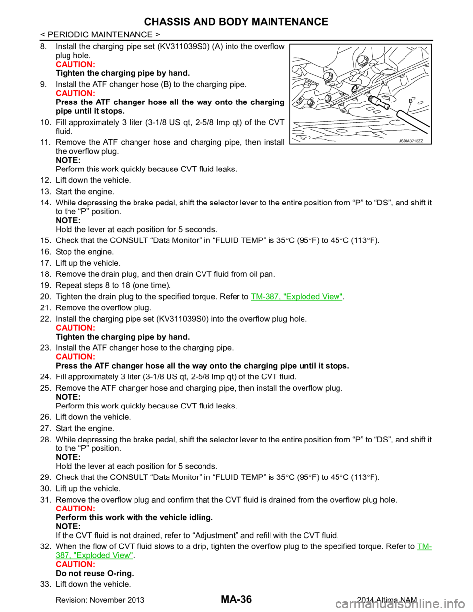
8. Install the charging pipe set (KV311039S0) (A) into the overflowplug hole.
CAUTION:
Tighten the charging pipe by hand.
9. Install the ATF changer hose (B) to the charging pipe. CAUTION:
Press the ATF changer hose all the way onto the charging
pipe until it stops.
10. Fill approximately 3 liter (3-1/8 US qt, 2-5/8 lmp qt) of the CVT
fluid.
11. Remove the ATF changer hose and charging pipe, then install the overflow plug.
NOTE:
Perform this work quickly because CVT fluid leaks.
12. Lift down the vehicle.
13. Start the engine.
14. While depressing the brake pedal, shift the selector lever to the entire position from “P” to “DS”, and shift it to the “P” position.
NOTE:
Hold the lever at each position for 5 seconds.
15. Check that the CONSULT “Data Monitor” in “FLUID TEMP” is 35 °C (95 °F) to 45 °C (113 °F).
16. Stop the engine.
17. Lift up the vehicle.
18. Remove the drain plug, and then drain CVT fluid from oil pan.
19. Repeat steps 8 to 18 (one time).
20. Tighten the drain plug to the specified torque. Refer to TM-387, "Exploded View"
.
21. Remove the overflow plug.
22. Install the charging pipe set (KV311039S0) into the overflow plug hole. CAUTION:
Tighten the charging pipe by hand.
23. Install the ATF changer hose to the charging pipe. CAUTION:
Press the ATF changer hose all the way onto the charging pipe until it stops.
24. Fill approximately 3 liter (3-1/8 US qt, 2-5/8 lmp qt) of the CVT fluid.
25. Remove the ATF changer hose and charging pipe, then install the overflow plug. NOTE:
Perform this work quickly because CVT fluid leaks.
26. Lift down the vehicle.
27. Start the engine.
28. While depressing the brake pedal, shift the selector lever to the entire position from “P” to “DS”, and shift it to the “P” position.
NOTE:
Hold the lever at each position for 5 seconds.
29. Check that the CONSULT “Data Monitor” in “FLUID TEMP” is 35 °C (95 °F) to 45 °C (113 °F).
30. Lift up the vehicle.
31. Remove the overflow plug and confirm that the CV T fluid is drained from the overflow plug hole.
CAUTION:
Perform this work with the vehicle idling.
NOTE:
If the CVT fluid is not drained, refer to “Adjustment” and refill with the CVT fluid.
32. When the flow of CVT fluid slows to a drip, tighten the overflow plug to the specified torque. Refer to TM-
387, "Exploded View".
CAUTION:
Do not reuse O-ring.
33. Lift down the vehicle.
JSDIA3713ZZ
Revision: November 20132014 Altima NAM
Page 3246 of 4801

MIR-16
< SYMPTOM DIAGNOSIS >
SQUEAK AND RATTLE TROUBLE DIAGNOSES
1. Loose harness or harness connectors.
2. Front console map/reading lamp lens loose.
3. Loose screws at console attachment points.
SEATS
When isolating seat noise it's important to note the pos ition the seat is in and the load placed on the seat when
the noise is present. These conditions should be dupl icated when verifying and isolating the cause of the
noise.
Cause of seat noise include:
1. Headrest rods and holder
2. A squeak between the seat pad cushion and frame
3. The rear seatback lock and bracket
These noises can be isolated by moving or pressing on the suspected components while duplicating the con-
ditions under which the noise occurs. Most of thes e incidents can be repaired by repositioning the component
or applying urethane tape to the contact area.
UNDERHOOD
Some interior noise may be caused by components under the hood or on the engine wall. The noise is then
transmitted into the passenger compartment.
Causes of transmitted underhood noise include:
1. Any component installed to the engine wall
2. Components that pass through the engine wall
3. Engine wall mounts and connectors
4. Loose radiator installation pins
5. Hood bumpers out of adjustment
6. Hood striker out of adjustment
These noises can be difficult to isolate since they cannot be reached from the interior of the vehicle. The best
method is to secure, move or insulate one component at a time and test drive the vehicle. Also, engine rpm or
load can be changed to isolate the noise. Repairs can usually be made by moving, adjusting, securing, or
insulating the component causing the noise.
Revision: November 20132014 Altima NAMRevision: November 20132014 Altima NAM
Page 3266 of 4801

MWI
SYSTEMMWI-11
< SYSTEM DESCRIPTION >
C
D E
F
G H
I
J
K L
M B
A
O P
SPEEDOMETER
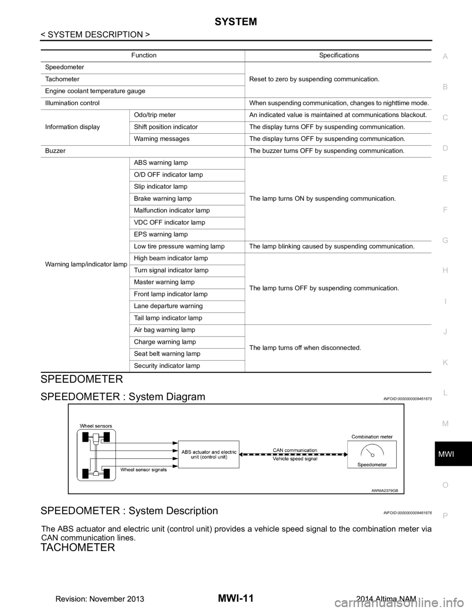
SPEEDOMETER : System DiagramINFOID:0000000009461675
SPEEDOMETER : System DescriptionINFOID:0000000009461676
The ABS actuator and electric unit (control unit) provi des a vehicle speed signal to the combination meter via
CAN communication lines.
TACHOMETER
Function Specifications
Speedometer Reset to zero by suspending communication.
Tachometer
Engine coolant temperature gauge
Illumination control When suspending communication, changes to nighttime mode.
Information display Odo/trip meter An indicated value is maintained at communications blackout.
Shift position indicator The display turns OFF by suspending communication.
Warning messages The display turns OFF by suspending communication.
Buzzer The buzzer turns OFF by suspending communication.
Warning lamp/indicator lamp ABS warning lamp
The lamp turns ON by suspending communication.
O/D OFF indicator lamp
Slip indicator lamp
Brake warning lamp
Malfunction indicator lamp
VDC OFF indicator lamp
EPS warning lamp
Low tire pressure warning lamp The lamp blinking caused by suspending communication.
High beam indicator lamp
The lamp turns OFF by suspending communication.
Turn signal indicator lamp
Master warning lamp
Front lamp indicator lamp
Lane departure warning
Tail lamp indicator lamp
Air bag warning lamp
The lamp turns off when disconnected.
Charge warning lamp
Seat belt warning lamp
Security indicator lamp
AWNIA2379GB
Revision: November 20132014 Altima NAMRevision: November 20132014 Altima NAM
Page 3268 of 4801

MWI
SYSTEMMWI-13
< SYSTEM DESCRIPTION >
C
D E
F
G H
I
J
K L
M B
A
O P
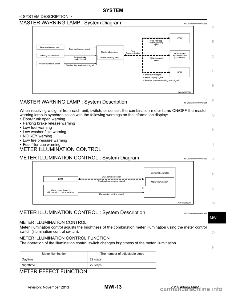
MASTER WARNING LAMP : System DiagramINFOID:0000000009461683
MASTER WARNING LAMP : System DescriptionINFOID:0000000009461684
When receiving a signal from each unit, switch, or s ensor, the combination meter turns ON/OFF the master
warning lamp in synchronization with the following warnings on the information display:
• Door/trunk open warning
• Parking brake release warning
• Low fuel warning
• Low washer fluid warning
• NO KEY warning
• Low tire pressure warning
• Fuel filler cap warning
METER ILLUMINATION CONTROL
METER ILLUMINATION CONTROL : System DiagramINFOID:0000000009461685
METER ILLUMINATION CONTROL : System DescriptionINFOID:0000000009461686
METER ILLUMINATION CONTROL
Meter illumination control adjusts the brightness of the combination meter illumination using the meter control
switch (illumination control switch).
METER ILLUMINATION CONTROL FUNCTION
The operation of the illumination control switch changes brightness of the meter illumination.
METER EFFECT FUNCTION
AWNIA2975GB
AWNIA2548GB
Meter illumination The number of adjustable steps
Daytime 22 steps
Nighttime 22 steps
Revision: November 20132014 Altima NAMRevision: November 20132014 Altima NAM
Page 3282 of 4801

MWI
COMBINATION METERMWI-27
< ECU DIAGNOSIS INFORMATION >
C
D E
F
G H
I
J
K L
M B
A
O PFail-SafeINFOID:0000000009461695
FA I L - S A F E
The combination meter activates the fail-safe contro l if CAN communication with each unit is malfunctioning.
DTC IndexINFOID:0000000009461696
52
(P) Ground O/D OFF/SPORT switch Input Ignition
switch
ON O/D OFF switch pressed 0 V
Other than the above 5 V
Te r m i n a l N o .
(Wire color) Description
ConditionVa l u e
(Approx.)
+ – Signal name Input/
Output
Function Specifications
Speedometer Reset to zero by suspending communication.
Tachometer
Engine coolant temperature gauge
Illumination control When suspending communication, changes to nighttime mode.
Information display Odo/trip meter An indicated value is maintained at communications blackout.
Shift position indicator The display turns OFF by suspending communication.
Warning messages The display turns OFF by suspending communication.
Buzzer The buzzer turns OFF by suspending communication.
Warning lamp/indicator lamp ABS warning lamp
The lamp turns ON by suspending communication.
O/D OFF indicator lamp
Slip indicator lamp
Brake warning lamp
Malfunction indicator lamp
VDC OFF indicator lamp
EPS warning lamp
Low tire pressure warning lamp The lamp blinking caused by suspending communication.
High beam indicator lamp
The lamp turns OFF by suspending communication.
Turn signal indicator lamp
Master warning lamp
Front lamp indicator lamp
Lane departure warning
Tail lamp indicator lamp
Air bag warning lamp
The lamp turns off when disconnected.
Charge warning lamp
Seat belt warning lamp
Security indicator lamp
Display contents of CONSULT Diagnostic item is detected when... Refer to
CAN COMM CIRCUIT
[U1000] When combination meter is not transmitting or receiving CAN communication signal for 2
seconds or more. MWI-53
CONTROL UNIT (CAN)
[U1010] When detecting error during the initial diagnosis of the CAN controller of combination
meter. MWI-54
Revision: November 20132014 Altima NAMRevision: November 20132014 Altima NAM
Page 3336 of 4801

MWI
NORMAL OPERATING CONDITIONMWI-81
< SYMPTOM DIAGNOSIS >
C
D E
F
G H
I
J
K L
M B
A
O P
NORMAL OPERATING CONDITION
COMPASS
COMPASS : DescriptionINFOID:0000000009461756
COMPASS
• The electronic compass is highly protected from changes in most magnetic fields. However, some large
changes in magnetic fields can affect it. Some exampl es are (but not limited to): high tension power lines,
large steel buildings, subways, steel bridges, automatic car washes, large piles of scrap metal, etc. While
this does not happen very often, it is possible.
• During normal operation, the Compass Mirror will cont inuously update the compass calibration to adjust for
gradual changes in the vehicle's magnetic "remnant" field. If the vehicle is subjected to high magnetic influ-
ences, the compass may appear to indicate false headings , become locked, or appear that it is unable to be
calibrated. If this occurs, perform the calibration procedure.
• If at any time the compass continually displays the inco rrect direction or the reading is erratic or locked, ver-
ify the correct zone variance.
Symptom Chart
Symptom Cause Solution / Reference
The compass display reads "C".
• Compass is not calibrated.
• Incorrect zone variance setting.
• Large change in magnetic field (Steel bridges, subways, concentrations of
metal, car washes, etc.)
• Compass was calibrated incorrectly or
in the presence of a strong magnetic
field. Perform Calibration. Refer to
MWI-16,
"COMPASS : Description".
Compass shows the wrong direction.
Compass does not change direction ap-
pears "Locked".
Compass does not show all the directions,
one or more is missing.
The compass was calibrated but it "loses"
calibration.
On long trips the compass shows the
wrong direction. Perform Zone Variatio
n Setting if correct
reading is desired in that location. Refer to
MWI-16, "COMPASS : Description"
.
Revision: November 20132014 Altima NAMRevision: November 20132014 Altima NAM
Page 3361 of 4801
![NISSAN TEANA 2014 Service Manual
PCS-12
< ECU DIAGNOSIS INFORMATION >[IPDM E/R]
IPDM E/R (INTELLIGENT POWER DI
STRIBUTION MODULE ENGINE ROOM)
ECU DIAGNOSIS INFORMATION
IPDM E/R (INTELLIGENT POWER DISTRIBUTION MODULE ENGINE
ROOM)
Re NISSAN TEANA 2014 Service Manual
PCS-12
< ECU DIAGNOSIS INFORMATION >[IPDM E/R]
IPDM E/R (INTELLIGENT POWER DI
STRIBUTION MODULE ENGINE ROOM)
ECU DIAGNOSIS INFORMATION
IPDM E/R (INTELLIGENT POWER DISTRIBUTION MODULE ENGINE
ROOM)
Re](/manual-img/5/57390/w960_57390-3360.png)
PCS-12
< ECU DIAGNOSIS INFORMATION >[IPDM E/R]
IPDM E/R (INTELLIGENT POWER DI
STRIBUTION MODULE ENGINE ROOM)
ECU DIAGNOSIS INFORMATION
IPDM E/R (INTELLIGENT POWER DISTRIBUTION MODULE ENGINE
ROOM)
Reference ValueINFOID:0000000009461603
VALUES ON THE DIAGNOSIS TOOL
Monitor Item Condition Value/Status
RAD FAN REQ Engine idle speed Changes depending on engine cool-
ant temperature, air conditioner op-
eration status, vehicle speed, etc. 1, 2, 3, 4
AC COMP REQ Engine running A/C switch OFF Off
A/C switch ON
(Compressor is operating) On
TAIL&CLR REQ Lighting switch OFF Off
Lighting switch 1ST, 2ND, HI or AUTO (Light is illuminated) On
HL LO REQ Lighting switch OFF Off
Lighting switch 2ND HI or AUTO (Light is illuminated) On
HL HI REQ Lighting switch OFF Off
Lighting switch HI On
FR FOG REQ Lighting switch 2ND or
AUTO (Light is illuminated) Front fog lamp switch OFF Off
• Front fog lamp switch ON
• Daytime running light activated (Only for Canada models) On
FR WIP REQ Ignition switch ON Front wiper switch OFF STOP
Front wiper switch INT 1LOW
Front wiper switch LO Low
Front wiper switch HI Hi
WIP AUTO STOP Ignition switch ON Front wiper stop position STOP P
Any position other than front wiper
stop position ACT P
WIP PROT Ignition switch ON Front wiper operates normally Off
Front wiper stops at fail-safe opera-
tion BLOCK
IGN RLY1 -REQ Ignition switch OFF or ACC Off
Ignition switch ON On
IGN RLY Ignition switch OFF or ACC Off
Ignition switch ON On
PUSH SW Release the push-button ignition switch Off
Press the push-button ignition switch On
INTER/NP SW Ignition switch ON CVT selector lever in any position
other than P or N Off
CVT selector lever in P or N position On
ST RLY CONT Ignition switch ON Off
At engine cranking On
IHBT RLY -REQ Ignition switch ON Off
At engine cranking On
Revision: November 20132014 Altima NAMRevision: November 20132014 Altima NAM
Page 3369 of 4801
![NISSAN TEANA 2014 Service Manual
PCS-20
< ECU DIAGNOSIS INFORMATION >[IPDM E/R]
IPDM E/R (INTELLIGENT POWER DI
STRIBUTION MODULE ENGINE ROOM)
IGNITION RELAY MALFUNCTION DETECTION FUNCTION
• IPDM E/R monitors the voltage at the con NISSAN TEANA 2014 Service Manual
PCS-20
< ECU DIAGNOSIS INFORMATION >[IPDM E/R]
IPDM E/R (INTELLIGENT POWER DI
STRIBUTION MODULE ENGINE ROOM)
IGNITION RELAY MALFUNCTION DETECTION FUNCTION
• IPDM E/R monitors the voltage at the con](/manual-img/5/57390/w960_57390-3368.png)
PCS-20
< ECU DIAGNOSIS INFORMATION >[IPDM E/R]
IPDM E/R (INTELLIGENT POWER DI
STRIBUTION MODULE ENGINE ROOM)
IGNITION RELAY MALFUNCTION DETECTION FUNCTION
• IPDM E/R monitors the voltage at the contact circuit and excitation coil circuit of the ignition relay inside it.
• IPDM E/R judges the ignition relay error if the voltage differs between the contact circuit and the excitation
coil circuit.
• If the ignition relay cannot turn OFF due to contact seiz ure, it activates the tail lamp relay for 10 minutes to
alert the user to the ignition relay malfunction when the ignition switch is turned OFF.
NOTE:
The tail lamp turns OFF when the ignition switch is turned ON.
FRONT WIPER CONTROL
IPDM E/R detects front wiper stop posit ion by a front wiper auto stop signal.
When a front wiper auto stop signal is in the conditions listed below, IPDM E/R stops power supply to wiper
after repeating a front wiper 10 second activation and 20 second stop five times.
NOTE:
This operation status can be confirmed on the IPDM E/ R “Data Monitor” that displays “BLOCK” for the item
“WIP PROT” while the wiper is stopped.
STARTER MOTOR PROTECTION FUNCTION
IPDM E/R turns OFF the starter control relay to protect the starter motor when the starter control relay remains
active for 90 seconds.
DTC IndexINFOID:0000000009461605
NOTE:
The details of TIME display are as follows.
• CRNT: The malfunctions that are detected now
• 1 - 39: The number is indicated when it is normal at present and a malfunction was detected in the past. It
increases like 0 → 1 → 2 ··· 38 → 39 after returning to the normal condition whenever IGN OFF → ON. It is
fixed to 39 until the self-diagnosis results are erased if it is over 39. It returns to 0 when a malfunction is
detected again in the process.
DTC Ignition switch Ignition relay Tail lamp relay
—ONON—
—OFFOFF—
B2098: IGN RELAY ON OFF ON ON (10 minutes)
B2099: IGN RELAY OFF ON OFF —
Ignition switch Front wiper switch Auto stop signal
ON OFF
Front wiper stop position signal cannot be
input 10 seconds.
ON The signal does not change for 10 seconds.
CONSULT display Fail-safe TIMENOTERefer to
No DTC is detected. Further testing may be required. — — — —
U1000: CAN COMM CIRCUIT ×CRNT 1 – 39 PCS-27
U1010: CONTROL UNIT (CAN) ×CRNT 1 – 39 PCS-28
B2098: IGN RELAY ON ×CRNT 1 – 39 PCS-29
B2099: IGN RELAY OFF — CRNT 1 – 39 PCS-30
B210B: INHIBIT relay ON stuck failure — CRNT 1 – 39 SEC-73
B210C: INHIBIT relay OFF stuck failure — CRNT 1 – 39 SEC-74
B210D: STARTER relay ON stuck failure — CRNT 1 – 39 SEC-76
B210E: STARTER relay OFF stuck failure — CRNT 1 – 39SEC-78
B210F: Interlock/NP switch ON stuck failure — CRNT 1 – 39 SEC-80
B2110: Interlock/NP switch OFF stuck failure — CRNT 1 – 39 SEC-82
Revision: November 20132014 Altima NAMRevision: November 20132014 Altima NAM