2014 NISSAN TEANA fuse diagram
[x] Cancel search: fuse diagramPage 3433 of 4801

PG
PG-1
ELECTRICAL & POWER CONTROL
C
D E
F
G H
I
J
K L
B
SECTION PG
A
O P
N
CONTENTS
POWER SUPPLY, GROUND & CIRCUIT ELEMENTS
PRECAUTION ................
...............................2
PRECAUTIONS .............................................. .....2
Precaution for Supplemental Restraint System
(SRS) "AIR BAG" and "SEAT BELT PRE-TEN-
SIONER" ............................................................. ......
2
PREPARATION ............................................3
PREPARATION .............................................. .....3
Special Service Tool ........................................... ......3
Commercial Service Tool ..........................................3
BASIC INSPECTION ....................................4
BATTERY ....................................................... .....4
How to Handle Battery ........................................ ......4
Work Flow ........................................................... ......4
INSPECTION AND ADJUSTMENT .....................7
ADDITIONAL SERVICE WHEN REMOVING BAT-
TERY NEGATIVE TERMINAL ............................... ......
7
ADDITIONAL SERVICE WHEN REMOVING
BATTERY NEGATIVE TERMINAL : Special Re-
pair Requirement ................................................. ......
7
DTC/CIRCUIT DIAGNOSIS ..........................8
POWER SUPPLY ROUTING CIRCUIT .......... .....8
Wiring Diagram — Battery Power Supply — ....... ......8
Wiring Diagram — Accessory Power Supply — .....15
Wiring Diagram — Ignition Power Supply — ..........19
Fuse ........................................................................28
Fusible Link .............................................................28
GROUND ...........................................................29
Ground Distribution .............................................. ....29
HARNESS .........................................................39
Harness Layout ................................................... ....39
ELECTRICAL UNITS LOCATION ....................61
Electrical Units Location ..........................................61
HARNESS CONNECTOR .................................65
Description ...............................................................65
STANDARDIZED RELAY .................................68
Description ...............................................................68
FUSE BLOCK - JUNCTION BOX (J/B) ............70
Terminal Arrangement .............................................70
FUSE, FUSIBLE LINK AND RELAY BOX ........71
Terminal Arrangement .............................................71
IPDM E/R (INTELLIGENT POWER DISTRI-
BUTION MODULE ENGINE ROOM) ................
72
Fuse, Connector and Terminal Arrangement ...... ....72
REMOVAL AND INSTALLATION ...............73
BATTERY ..........................................................73
Exploded View ..................................................... ....73
Removal and Installation (Battery) ..........................73
Removal and Installation (Battery Tray) ..................74
SERVICE DATA AND SPECIFICATIONS
(SDS) ............... .............................................
75
BATTERY ..........................................................75
Battery ................................................................. ....75
Revision: November 20132014 Altima NAM
Page 3536 of 4801
![NISSAN TEANA 2014 Service Manual
POWER SUPPLY AND GROUND CIRCUITPWC-29
< DTC/CIRCUIT DIAGNOSIS > [LH FRONT ONLY ANTI-PINCH]
C
D E
F
G H
I
J
L
M A
B
PWC
N
O P
DTC/CIRCUIT DIAGNOSIS
POWER SUPPLY AND GROUND CIRCUIT
BCM
BCM : Diagnosi NISSAN TEANA 2014 Service Manual
POWER SUPPLY AND GROUND CIRCUITPWC-29
< DTC/CIRCUIT DIAGNOSIS > [LH FRONT ONLY ANTI-PINCH]
C
D E
F
G H
I
J
L
M A
B
PWC
N
O P
DTC/CIRCUIT DIAGNOSIS
POWER SUPPLY AND GROUND CIRCUIT
BCM
BCM : Diagnosi](/manual-img/5/57390/w960_57390-3535.png)
POWER SUPPLY AND GROUND CIRCUITPWC-29
< DTC/CIRCUIT DIAGNOSIS > [LH FRONT ONLY ANTI-PINCH]
C
D E
F
G H
I
J
L
M A
B
PWC
N
O P
DTC/CIRCUIT DIAGNOSIS
POWER SUPPLY AND GROUND CIRCUIT
BCM
BCM : Diagnosis ProcedureINFOID:0000000009955265
Regarding Wiring Diagram information, refer to BCS-55, "Wiring Diagram".
1. CHECK FUSE AND FUSIBLE LINK
Check that the following fuse and fusible link are not blown.
Is the fuse or fusible link blown?
YES >> Replace the blown fuse or fusible link after repairing the affected circuit.
NO >> GO TO 2
2. CHECK POWER SUPPLY CIRCUIT
1. Disconnect BCM connector M21.
2. Check voltage between BCM connector M21 terminals 131, 139 and ground.
Is the inspection result normal?
YES >> GO TO 3
NO >> Repair or replace harness or connectors.
3. CHECK GROUND CIRCUIT
Check continuity between BCM connector M21 terminals 134, 143 and ground.
Is the inspection result normal?
YES >> Inspection End.
NO >> Repair or replace harness or connectors.
POWER WINDOW MAIN SWITCH
POWER WINDOW MAIN SWITCH : DescriptionINFOID:0000000009460835
• BCM supplies power.
• It operates each power window motor via corresponding power window switch and makes window move up/
down when main power window and door lock/unlock switch is operated.
Terminal No. Signal name Fuse and fusible link No.
139 Fusible link battery power I (40A)
131 BCM battery fuse 1 (10A)
BCM GroundVo l ta g e
(Approx.)
Connector Terminal
M21 131
—Batteryvoltage
139
BCM Ground Continuity
Connector Terminal
M21 134
—Yes
143
Revision: November 20132014 Altima NAMRevision: November 20132014 Altima NAM
Page 3602 of 4801
![NISSAN TEANA 2014 Service Manual
POWER SUPPLY AND GROUND CIRCUITPWC-95
< DTC/CIRCUIT DIAGNOSIS > [LH & RH FRONT ANTI-PINCH]
C
D E
F
G H
I
J
L
M A
B
PWC
N
O P
DTC/CIRCUIT DIAGNOSIS
POWER SUPPLY AND GROUND CIRCUIT
BCM
BCM : Diagnosi NISSAN TEANA 2014 Service Manual
POWER SUPPLY AND GROUND CIRCUITPWC-95
< DTC/CIRCUIT DIAGNOSIS > [LH & RH FRONT ANTI-PINCH]
C
D E
F
G H
I
J
L
M A
B
PWC
N
O P
DTC/CIRCUIT DIAGNOSIS
POWER SUPPLY AND GROUND CIRCUIT
BCM
BCM : Diagnosi](/manual-img/5/57390/w960_57390-3601.png)
POWER SUPPLY AND GROUND CIRCUITPWC-95
< DTC/CIRCUIT DIAGNOSIS > [LH & RH FRONT ANTI-PINCH]
C
D E
F
G H
I
J
L
M A
B
PWC
N
O P
DTC/CIRCUIT DIAGNOSIS
POWER SUPPLY AND GROUND CIRCUIT
BCM
BCM : Diagnosis ProcedureINFOID:0000000009955268
Regarding Wiring Diagram information, refer to BCS-55, "Wiring Diagram".
1. CHECK FUSE AND FUSIBLE LINK
Check that the following fuse and fusible link are not blown.
Is the fuse or fusible link blown?
YES >> Replace the blown fuse or fusible link after repairing the affected circuit.
NO >> GO TO 2
2. CHECK POWER SUPPLY CIRCUIT
1. Disconnect BCM connector M21.
2. Check voltage between BCM connector M21 terminals 131, 139 and ground.
Is the inspection result normal?
YES >> GO TO 3
NO >> Repair or replace harness or connectors.
3. CHECK GROUND CIRCUIT
Check continuity between BCM connector M21 terminals 134, 143 and ground.
Is the inspection result normal?
YES >> Inspection End.
NO >> Repair or replace harness or connectors.
POWER WINDOW MAIN SWITCH
POWER WINDOW MAIN SWITCH : DescriptionINFOID:0000000009460913
• BCM supplies power.
• It operates each power window motor via corresponding power window switch and makes window move up/
down when main power window and door lock/unlock switch is operated.
Terminal No. Signal name Fuse and fusible link No.
139 Fusible link battery power I (40A)
131 BCM battery fuse 1 (10A)
BCM GroundVo l ta g e
(Approx.)
Connector Terminal
M21 131
—Batteryvoltage
139
BCM Ground Continuity
Connector Terminal
M21 134
—Yes
143
Revision: November 20132014 Altima NAMRevision: November 20132014 Altima NAM
Page 3686 of 4801

POWER SUPPLY AND GROUND CIRCUITRF-21
< DTC/CIRCUIT DIAGNOSIS >
C
D E
F
G H
I
J
L
M A
B
RF
N
O P
DTC/CIRCUIT DIAGNOSIS
POWER SUPPLY AND GROUND CIRCUIT
BCM
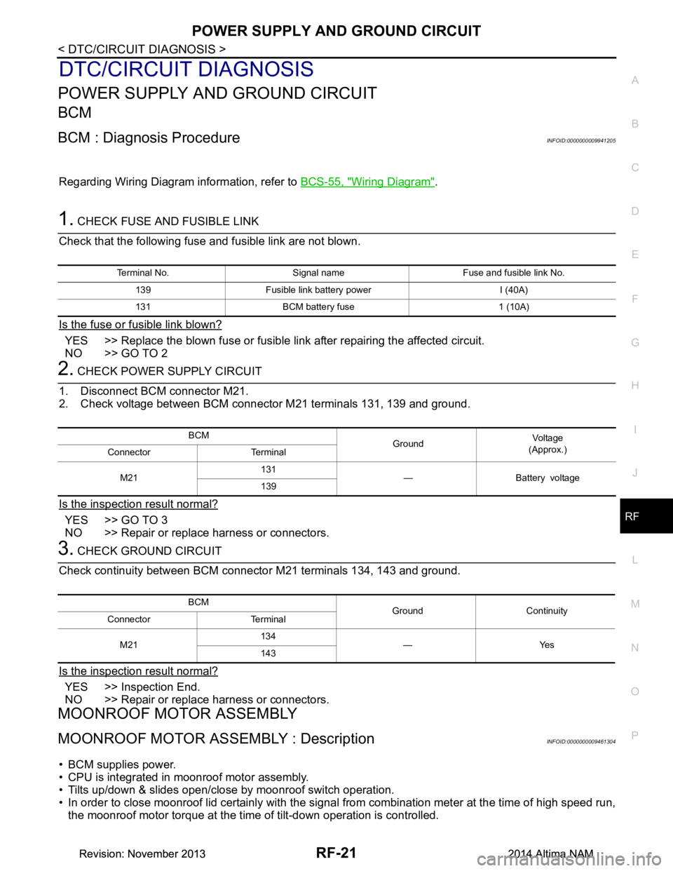
BCM : Diagnosis ProcedureINFOID:0000000009941205
Regarding Wiring Diagram information, refer to BCS-55, "Wiring Diagram".
1. CHECK FUSE AND FUSIBLE LINK
Check that the following fuse and fusible link are not blown.
Is the fuse or fusible link blown?
YES >> Replace the blown fuse or fusible link after repairing the affected circuit.
NO >> GO TO 2
2. CHECK POWER SUPPLY CIRCUIT
1. Disconnect BCM connector M21.
2. Check voltage between BCM connector M21 terminals 131, 139 and ground.
Is the inspection result normal?
YES >> GO TO 3
NO >> Repair or replace harness or connectors.
3. CHECK GROUND CIRCUIT
Check continuity between BCM connector M21 terminals 134, 143 and ground.
Is the inspection result normal?
YES >> Inspection End.
NO >> Repair or replace harness or connectors.
MOONROOF MOTOR ASSEMBLY
MOONROOF MOTOR ASSEMBLY : DescriptionINFOID:0000000009461304
• BCM supplies power.
• CPU is integrated in moonroof motor assembly.
• Tilts up/down & slides open/close by moonroof switch operation.
• In order to close moonroof lid certainly with the signal from combination meter at the time of high speed run,
the moonroof motor torque at the time of tilt-down operation is controlled.
Terminal No. Signal name Fuse and fusible link No.
139 Fusible link battery power I (40A)
131 BCM battery fuse 1 (10A)
BCM GroundVo l ta g e
(Approx.)
Connector Terminal
M21 131
—Batteryvoltage
139
BCM Ground Continuity
Connector Terminal
M21 134
—Yes
143
Revision: November 20132014 Altima NAMRevision: November 20132014 Altima NAM
Page 3919 of 4801

SEC-94
< DTC/CIRCUIT DIAGNOSIS >
B2555 STOP LAMP
B2555 STOP LAMP
DTC LogicINFOID:0000000009461150
DTC DETECTION LOGIC
DTC CONFIRMATION PROCEDURE
1.PERFORM DTC CONFIRMATION PROCEDURE
1. Depress the brake pedal and wait 1 second or more.
2. Check DTC in “Self-Diagnostic Result” mode of “BCM” using CONSULT.
Is DTC detected?
YES >> Go to SEC-94, "Diagnosis Procedure".
NO >> Inspection End.
Diagnosis ProcedureINFOID:0000000009461151
Regarding Wiring Diagram information, refer to SEC-29, "Wiring Diagram".
1. CHECK STOP LAMP SWITCH INPUT SIGNAL
1. Turn ignition switch OFF.
2. Disconnect BCM connector M17.
3. Check voltage between BCM harness connector and ground.
Is the inspection result normal?
YES >> GO TO 8.
NO >> GO TO 2.
2. CHECK POWER SOURCE (STOP LAMP SWITCH)
1. Disconnect stop lamp switch connector.
2. Check voltage between stop lamp switch connector E38 terminal 1 and ground.
Is the inspection result normal?
YES >> GO TO 3.
NO >> Check the following: • Harness for short or open between fuse block (J/B) and stop lamp switch
• 10A fuse (No. 10, located in fuse block [J/B])
3.CHECK STOP LAMP SWITCH
DTC No. Trouble diagnosis name DTC detecting condition Possible cause
B2555 STOP LAMP BCM makes a comparison between the
upper voltage and lower voltage of stop
lamp switch. It judges from their values to
detect the malfunctioning circuit. • Harness or connectors
(Stop lamp switch circuit is open or
shorted.)
• Stop lamp switch
•Fuse
•BCM
(+) (-) Condition Voltage (V)
BCM
Connector Terminal Ground Brake pedal Depressed Battery voltage
M17 27 Not depressed 0
Stop lamp switch GroundVoltage
Connector Terminal
E38 1 Battery voltage
Revision: November 20132014 Altima NAMRevision: November 20132014 Altima NAM
Page 3947 of 4801

SEC-122
< DTC/CIRCUIT DIAGNOSIS >
POWER SUPPLY AND GROUND CIRCUIT
POWER SUPPLY AND GROUND CIRCUIT
Diagnosis ProcedureINFOID:0000000009956232
Regarding Wiring Diagram information, refer to BCS-55, "Wiring Diagram".
1. CHECK FUSE AND FUSIBLE LINK
Check that the following fuse and fusible link are not blown.
Is the fuse or fusible link blown?
YES >> Replace the blown fuse or fusible link after repairing the affected circuit.
NO >> GO TO 2
2. CHECK POWER SUPPLY CIRCUIT
1. Disconnect BCM connector M21.
2. Check voltage between BCM connector M21 terminals 131, 139 and ground.
Is the inspection result normal?
YES >> GO TO 3
NO >> Repair or replace harness or connectors.
3. CHECK GROUND CIRCUIT
Check continuity between BCM connector M21 terminals 134, 143 and ground.
Is the inspection result normal?
YES >> Inspection End.
NO >> Repair or replace harness or connectors.
Terminal No. Signal name Fuse and fusible link No.
139 Fusible link battery power I (40A)
131 BCM battery fuse 1 (10A)
BCM GroundVo l ta g e
(Approx.)
Connector Terminal
M21 131
— Battery voltage
139
BCM Ground Continuity
Connector Terminal
M21 134
—Yes
143
Revision: November 20132014 Altima NAMRevision: November 20132014 Altima NAM
Page 3952 of 4801

SECURITY INDICATOR LAMPSEC-127
< DTC/CIRCUIT DIAGNOSIS >
C
D E
F
G H
I
J
L
M A
B
SEC
N
O P
SECURITY INDICATOR LAMP
Component Function CheckINFOID:0000000009461192
1.CHECK FUNCTION
1. Perform THEFT IND in ACTIVE TEST mode of IMMU of BCM using CONSULT.
2. Check security indicator lamp operation.
Is the inspection result normal?
YES >> Inspection End.
NO >> Go to SEC-127, "Diagnosis Procedure"
.
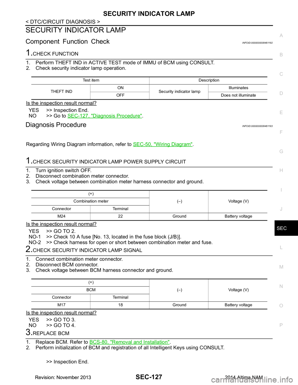
Diagnosis ProcedureINFOID:0000000009461193
Regarding Wiring Diagram information, refer to SEC-50, "Wiring Diagram".
1.CHECK SECURITY INDICATOR LAMP POWER SUPPLY CIRCUIT
1. Turn ignition switch OFF.
2. Disconnect combination meter connector.
3. Check voltage between combination meter harness connector and ground.
Is the inspection result normal?
YES >> GO TO 2.
NO-1 >> Check 10 A fuse [No. 13, lo cated in the fuse block (J/B)].
NO-2 >> Check harness for open or short between combination meter and fuse.
2.CHECK SECURITY INDICATOR LAMP SIGNAL
1. Connect combination meter connector.
2. Disconnect BCM connector.
3. Check voltage between BCM harness connector and ground.
Is the inspection result normal?
YES >> GO TO 3.
NO >> GO TO 4.
3.REPLACE BCM
1. Replace BCM. Refer to BCS-80, "Removal and Installation"
.
2. Perform initialization of BCM and registration of all Intelligent Keys using CONSULT.
>> Inspection End.
Test item Description
THEFT IND ON
Security indicator lamp Illuminates
OFF Does not illuminate
(+) (–) Voltage (V)
Combination meter
Connector Terminal M24 22 Ground Battery voltage
(+) (–) Voltage (V)
BCM
Connector Terminal M17 18 Ground Battery voltage
Revision: November 20132014 Altima NAMRevision: November 20132014 Altima NAM
Page 4124 of 4801

POWER SUPPLY AND GROUND CIRCUITST-21
< DTC/CIRCUIT DIAGNOSIS >
C
D E
F
H I
J
K L
M A
B
ST
N
O P
DTC/CIRCUIT DIAGNOSIS
POWER SUPPLY AND GROUND CIRCUIT
A/C AUTO AMP.
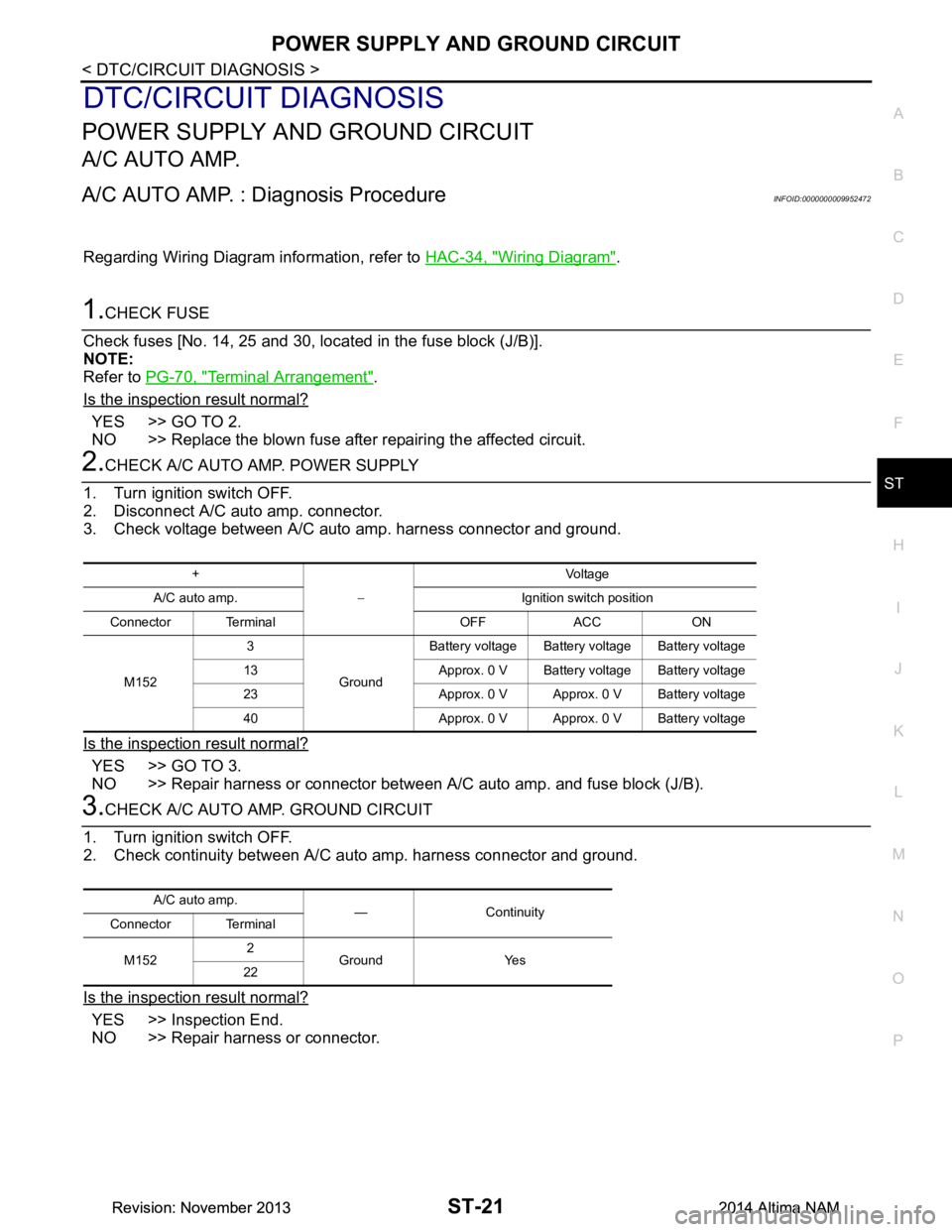
A/C AUTO AMP. : Diagnosis ProcedureINFOID:0000000009952472
Regarding Wiring Diagram information, refer to HAC-34, "Wiring Diagram".
1.CHECK FUSE
Check fuses [No. 14, 25 and 30, loca ted in the fuse block (J/B)].
NOTE:
Refer to PG-70, "Terminal Arrangement"
.
Is the inspection result normal?
YES >> GO TO 2.
NO >> Replace the blown fuse after repairing the affected circuit.
2.CHECK A/C AUTO AMP. POWER SUPPLY
1. Turn ignition switch OFF.
2. Disconnect A/C auto amp. connector.
3. Check voltage between A/C auto amp. harness connector and ground.
Is the inspection result normal?
YES >> GO TO 3.
NO >> Repair harness or connector between A/C auto amp. and fuse block (J/B).
3.CHECK A/C AUTO AMP. GROUND CIRCUIT
1. Turn ignition switch OFF.
2. Check continuity between A/C aut o amp. harness connector and ground.
Is the inspection result normal?
YES >> Inspection End.
NO >> Repair harness or connector.
+
− Voltag e
A/C auto amp. Ignition switch position
Connector Terminal OFF ACC ON
M152 3
GroundBattery voltage Battery voltage Battery voltage
13 Approx. 0 V Battery voltage Battery voltage
23 Approx. 0 V Approx. 0 V Battery voltage
40 Approx. 0 V Approx. 0 V Battery voltage
A/C auto amp. — Continuity
Connector Terminal
M152 2
Ground Yes
22
Revision: November 20132014 Altima NAMRevision: November 20132014 Altima NAM