2014 NISSAN TEANA fuse diagram
[x] Cancel search: fuse diagramPage 1182 of 4801
![NISSAN TEANA 2014 Service Manual
EC-182
< BASIC INSPECTION >[QR25DE]
FUEL PRESSURE
FUEL PRESSURE
Work ProcedureINFOID:0000000009462142
FUEL PRESSURE RELEASE
1.FUEL PRESSURE RELEASE
With CONSULT
1. Turn ignition switch ON.
2. Perfor NISSAN TEANA 2014 Service Manual
EC-182
< BASIC INSPECTION >[QR25DE]
FUEL PRESSURE
FUEL PRESSURE
Work ProcedureINFOID:0000000009462142
FUEL PRESSURE RELEASE
1.FUEL PRESSURE RELEASE
With CONSULT
1. Turn ignition switch ON.
2. Perfor](/manual-img/5/57390/w960_57390-1181.png)
EC-182
< BASIC INSPECTION >[QR25DE]
FUEL PRESSURE
FUEL PRESSURE
Work ProcedureINFOID:0000000009462142
FUEL PRESSURE RELEASE
1.FUEL PRESSURE RELEASE
With CONSULT
1. Turn ignition switch ON.
2. Perform “FUEL PRESSURE RELEA SE” in “WORK SUPPORT” mode of “ENGINE” using CONSULT.
3. Start engine.
4. After engine stalls, crank it two or three times to release all fuel pressure.
5. Turn ignition switch OFF.
Without CONSULT
1. Remove fuel pump fuse located in IPDM E/R. For the fuse number, refer to EC-117, "Wiring Diagram"
. For
the fuse arrangement, refer to PG-72, "Fuse, Connector and Terminal Arrangement"
.
2. Start engine.
3. After engine stalls, crank it two or three times to release all fuel pressure.
4. Turn ignition switch OFF.
5. Reinstall fuel pump fuse after servicing fuel system.
>> END
FUEL PRESSURE CHECK
CAUTION:
Before disconnecting fuel line, release fuel pr essure from fuel line to eliminate danger.
NOTE:
• Prepare pans or saucers under the disconnected fuel line because the fuel may spill out. The fuel
pressure cannot be completely released because th is models do not have fuel return system.
• Use Fuel Pressure Gauge Kit [SST: (J-44321)] to check fuel pressure.
1.FUEL PRESSURE CHECK
1. Release fuel pressure to zero.
2. Connect fuel tube adapter [SST:KV10120000] (B) to quick con-
nector.
3. Turn ignition switch ON and check for fuel leakage.
4. Start engine and check for fuel leakage.
5. Read the indication of fuel pressure gauge.
Is the inspection result normal?
YES >> INSPECTION END
NO >> GO TO 2.
2.CHECK FUEL HOSES AND FUEL TUBES
Check fuel hoses and fuel tubes for clogging.
Is the inspection result normal?
YES >> Replace “fuel filter and fuel pump assembly”. Refer to FL-6, "Removal and Installation".
NO >> Repair or replace error-detected parts.
A : Fuel pressure gauge
C : Fuel feed hose
: Vehicle front
At idling : Approximately 350 kPa (3.57 kg/cm2, 51 psi)
ALBIA0811ZZ
Revision: November 20132014 Altima NAMRevision: November 20132014 Altima NAM
Page 2355 of 4801
POWER SUPPLY AND GROUND CIRCUITEXL-89
< DTC/CIRCUIT DIAGNOSIS >
C
D E
F
G H
I
J
K
M A
B
EXL
N
O P
DTC/CIRCUIT DIAGNOSIS
POWER SUPPLY AND GROUND CIRCUIT
BCM (BODY CONTROL MODULE)
BCM (BODY CONTROL MODULE) : Diagnosis ProcedureINFOID:0000000009956493
Regarding Wiring Diagram information, refer to BCS-55, "Wiring Diagram".
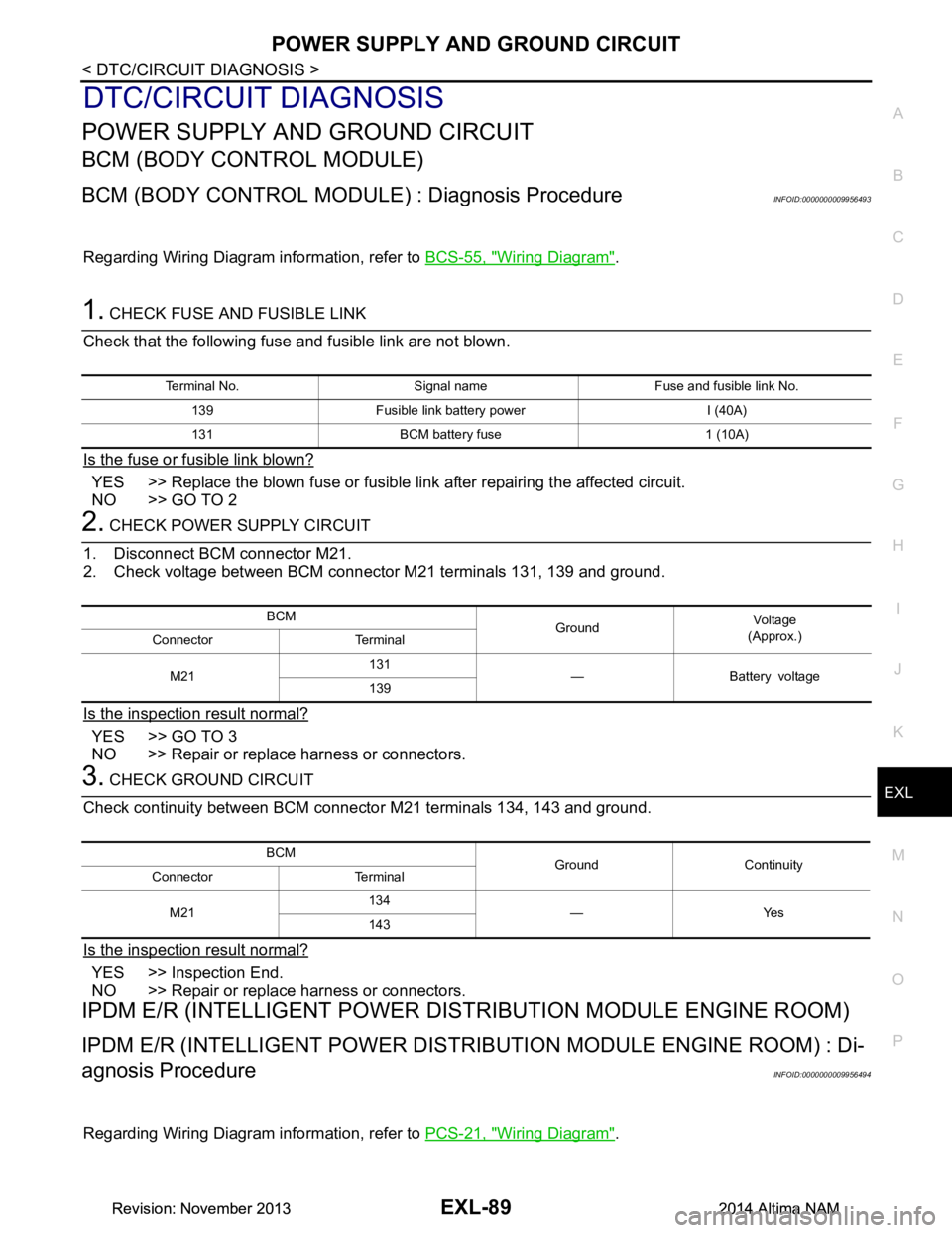
1. CHECK FUSE AND FUSIBLE LINK
Check that the following fuse and fusible link are not blown.
Is the fuse or fusible link blown?
YES >> Replace the blown fuse or fusible link after repairing the affected circuit.
NO >> GO TO 2
2. CHECK POWER SUPPLY CIRCUIT
1. Disconnect BCM connector M21.
2. Check voltage between BCM connector M21 terminals 131, 139 and ground.
Is the inspection result normal?
YES >> GO TO 3
NO >> Repair or replace harness or connectors.
3. CHECK GROUND CIRCUIT
Check continuity between BCM connector M21 terminals 134, 143 and ground.
Is the inspection result normal?
YES >> Inspection End.
NO >> Repair or replace harness or connectors.
IPDM E/R (INTELLIGENT POWER DIST RIBUTION MODULE ENGINE ROOM)
IPDM E/R (INTELLIGENT POWER DISTRIBUTION MODULE ENGINE ROOM) : Di-
agnosis Procedure
INFOID:0000000009956494
Regarding Wiring Diagram information, refer to PCS-21, "Wiring Diagram".
Terminal No. Signal name Fuse and fusible link No.
139 Fusible link battery power I (40A)
131 BCM battery fuse 1 (10A)
BCM GroundVo l ta g e
(Approx.)
Connector Terminal
M21 131
—Batteryvoltage
139
BCM Ground Continuity
Connector Terminal
M21 134
—Yes
143
Revision: November 20132014 Altima NAMRevision: November 20132014 Altima NAM
Page 2357 of 4801
HEADLAMP (HI) CIRCUITEXL-91
< DTC/CIRCUIT DIAGNOSIS >
C
D E
F
G H
I
J
K
M A
B
EXL
N
O P
HEADLAMP (HI) CIRCUIT
DescriptionINFOID:0000000009463577
The IPDM E/R (intelligent power distribution modul e engine room) controls the headlamp high relay based on
inputs from the BCM over the CAN communication li nes. When the headlamp high relay is energized, power
flows through fuses 34 and 35, located in the IPDM E/R. Power then flows to the front combination lamps to
the headlamp high beam.
Component Function CheckINFOID:0000000009463578
1.CHECK HEADLAMP (HI) OPERATION
WITHOUT CONSULT
1. Start IPDM E/R auto active test. Refer to PCS-8, "Diagnosis Description"
.
2. Check that the headlamp switches to the high beam. NOTE:
HI/LO is repeated 1 second each when using the IPDM E/R auto active test.
CONSULT
1. Select EXTERNAL LAMP of IP DM E/R active test item.
2. While operating the test items, check t hat the headlamp switches to the high beam.
Is the inspection result normal?
YES >> Headlamp (HI) circuit is normal.
NO >> Refer to EXL-91, "Diagnosis Procedure"
.
Diagnosis ProcedureINFOID:0000000009463579
Regarding Wiring Diagram information, refer to EXL-27, "Wiring Diagram - Halogen" or EXL-33, "Wiring Dia-
gram - Xenon".
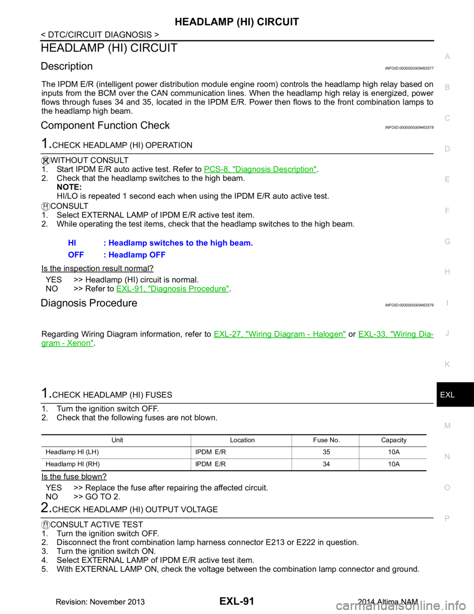
1.CHECK HEADLAMP (HI) FUSES
1. Turn the ignition switch OFF.
2. Check that the following fuses are not blown.
Is the fuse blown?
YES >> Replace the fuse after repairing the affected circuit.
NO >> GO TO 2.
2.CHECK HEADLAMP (HI) OUTPUT VOLTAGE
CONSULT ACTIVE TEST
1. Turn the ignition switch OFF.
2. Disconnect the front combination lamp harness connector E213 or E222 in question.
3. Turn the ignition switch ON.
4. Select EXTERNAL LAMP of IP DM E/R active test item.
5. With EXTERNAL LAMP ON, check the voltage between the combination lamp connector and ground.
HI : Headlamp switches to the high beam.
OFF : Headlamp OFF
Unit Location Fuse No. Capacity
Headlamp HI (LH) IPDM E/R 35 10A
Headlamp HI (RH) IPDM E/R 34 10A
Revision: November 20132014 Altima NAMRevision: November 20132014 Altima NAM
Page 2359 of 4801
HEADLAMP (LO) CIRCUITEXL-93
< DTC/CIRCUIT DIAGNOSIS >
C
D E
F
G H
I
J
K
M A
B
EXL
N
O P
HEADLAMP (LO) CIRCUIT
HEADLAMP (HALOGEN)
HEADLAMP (HALOGEN) : DescriptionINFOID:0000000009463580
The IPDM E/R (intelligent power distribution modul e engine room) controls the headlamp low relay based on
inputs from the BCM over the CAN communication li nes. When the headlamp low relay is energized, power
flows through fuses 36 and 37, located in the IPDM E/R. Power then flows to the front combination lamps to
the headlamp low beam.
HEADLAMP (HALOGEN) : Component Function CheckINFOID:0000000009463581
1.CHECK HEADLAMP (LO) OPERATION
WITHOUT CONSULT
1. Start IPDM E/R auto active test. Refer to PCS-8, "Diagnosis Description"
.
2. Check that the headlamp is turned ON.
NOTE:
HI/LO is repeated 1 second each when using the IPDM E/R auto active test.
CONSULT
1. Select EXTERNAL LAMP of IP DM E/R active test item.
2. While operating the test items, check that the headlamp is turned ON.
Is the inspection result normal?
YES >> Headlamp (LO) is normal.
NO >> Refer to EXL-93, "HEADLAMP (HALOGEN) : Diagnosis Procedure"
.
HEADLAMP (HALOGEN) : Diagnosis ProcedureINFOID:0000000009463582
Regarding Wiring Diagram information, refer to EXL-27, "Wiring Diagram - Halogen".
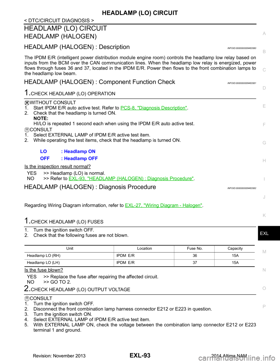
1.CHECK HEADLAMP (LO) FUSES
1. Turn the ignition switch OFF.
2. Check that the following fuses are not blown.
Is the fuse blown?
YES >> Replace the fuse after repairing the affected circuit.
NO >> GO TO 2.
2.CHECK HEADLAMP (LO) OUTPUT VOLTAGE
CONSULT
1. Turn the ignition switch OFF.
2. Disconnect the front combination lamp harness connector E212 or E223 in question.
3. Turn the ignition switch ON.
4. Select EXTERNAL LAMP of IP DM E/R active test item.
5. With EXTERNAL LAMP ON, check the voltage betw een the combination lamp connector E212 or E223
terminal 1 and ground. LO : Headlamp ON
OFF : Headlamp OFF
Unit Location Fuse No. Capacity
Headlamp LO (RH) IPDM E/R 36 15A
Headlamp LO (L H) IPDM E/R 37 15A
Revision: November 20132014 Altima NAMRevision: November 20132014 Altima NAM
Page 2361 of 4801
HEADLAMP (LO) CIRCUITEXL-95
< DTC/CIRCUIT DIAGNOSIS >
C
D E
F
G H
I
J
K
M A
B
EXL
N
O P
Is the inspection result normal?
YES >> Headlamp (LO) is normal.
NO >> Refer to EXL-95, "HEADLAMP (XEN ON) : Diagnosis Procedure"
.
HEADLAMP (XENON) : Diagnosis ProcedureINFOID:0000000009463585
Regarding Wiring Diagram information, refer to EXL-33, "Wiring Diagram - Xenon".
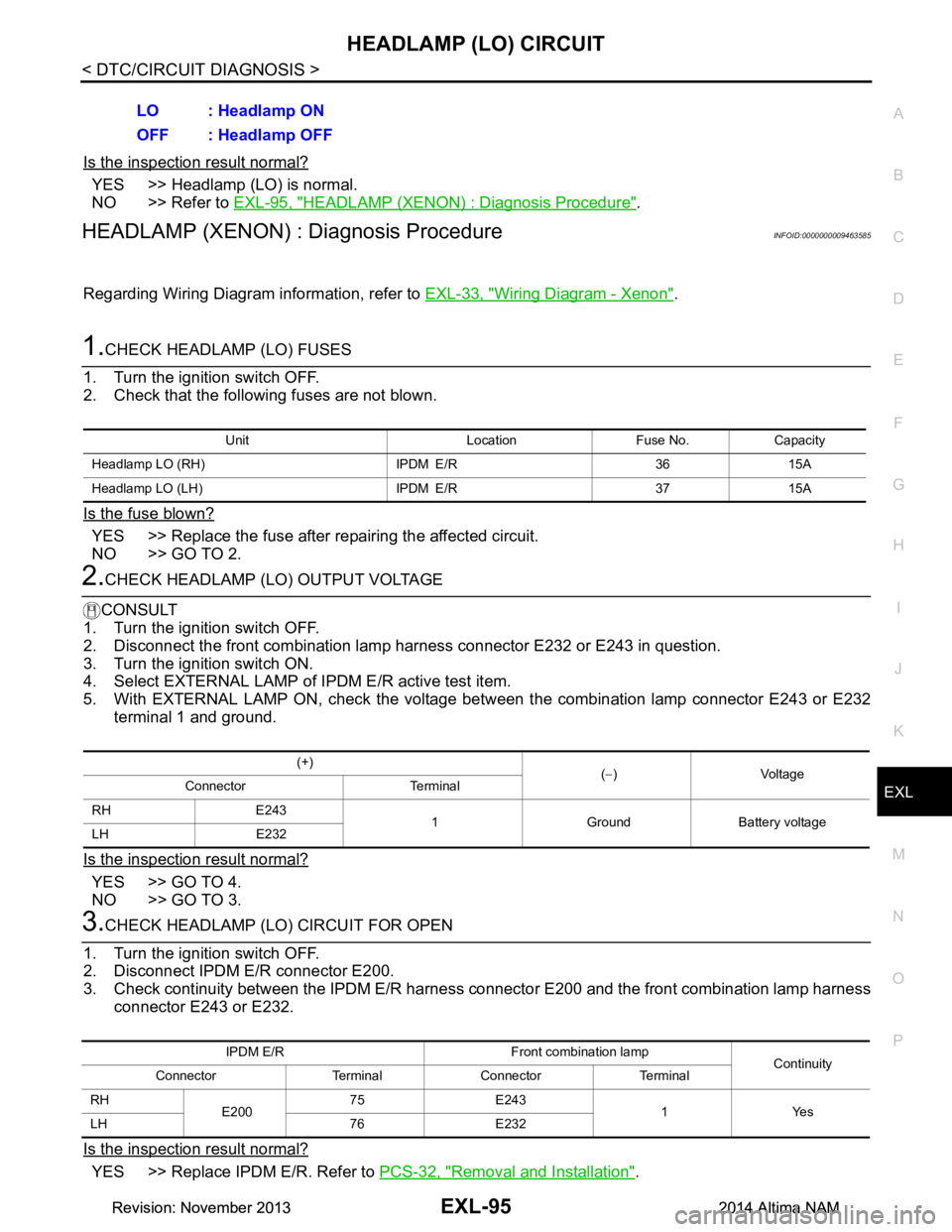
1.CHECK HEADLAMP (LO) FUSES
1. Turn the ignition switch OFF.
2. Check that the following fuses are not blown.
Is the fuse blown?
YES >> Replace the fuse after repairing the affected circuit.
NO >> GO TO 2.
2.CHECK HEADLAMP (LO) OUTPUT VOLTAGE
CONSULT
1. Turn the ignition switch OFF.
2. Disconnect the front combination lamp harness connector E232 or E243 in question.
3. Turn the ignition switch ON.
4. Select EXTERNAL LAMP of IP DM E/R active test item.
5. With EXTERNAL LAMP ON, check the voltage betw een the combination lamp connector E243 or E232
terminal 1 and ground.
Is the inspection result normal?
YES >> GO TO 4.
NO >> GO TO 3.
3.CHECK HEADLAMP (LO) CIRCUIT FOR OPEN
1. Turn the ignition switch OFF.
2. Disconnect IPDM E/R connector E200.
3. Check continuity between the IPDM E/R harness c onnector E200 and the front combination lamp harness
connector E243 or E232.
Is the inspection result normal?
YES >> Replace IPDM E/R. Refer to PCS-32, "Removal and Installation".
LO : Headlamp ON
OFF : Headlamp OFF
Unit Location Fuse No. Capacity
Headlamp LO (RH) IPDM E/R 36 15A
Headlamp LO (L H) IPDM E/R 37 15A
(+)
(− )Voltage
Connector Terminal
RH E243 1 Ground Battery voltage
LH E232
IPDM E/R Front combination lamp Continuity
Connector Terminal Connector Terminal
RH E20075 E243
1Yes
LH 76 E232
Revision: November 20132014 Altima NAMRevision: November 20132014 Altima NAM
Page 2364 of 4801
EXL-98
< DTC/CIRCUIT DIAGNOSIS >
DAYTIME LIGHT RELAY CIRCUIT
DAYTIME LIGHT RELAY CIRCUIT
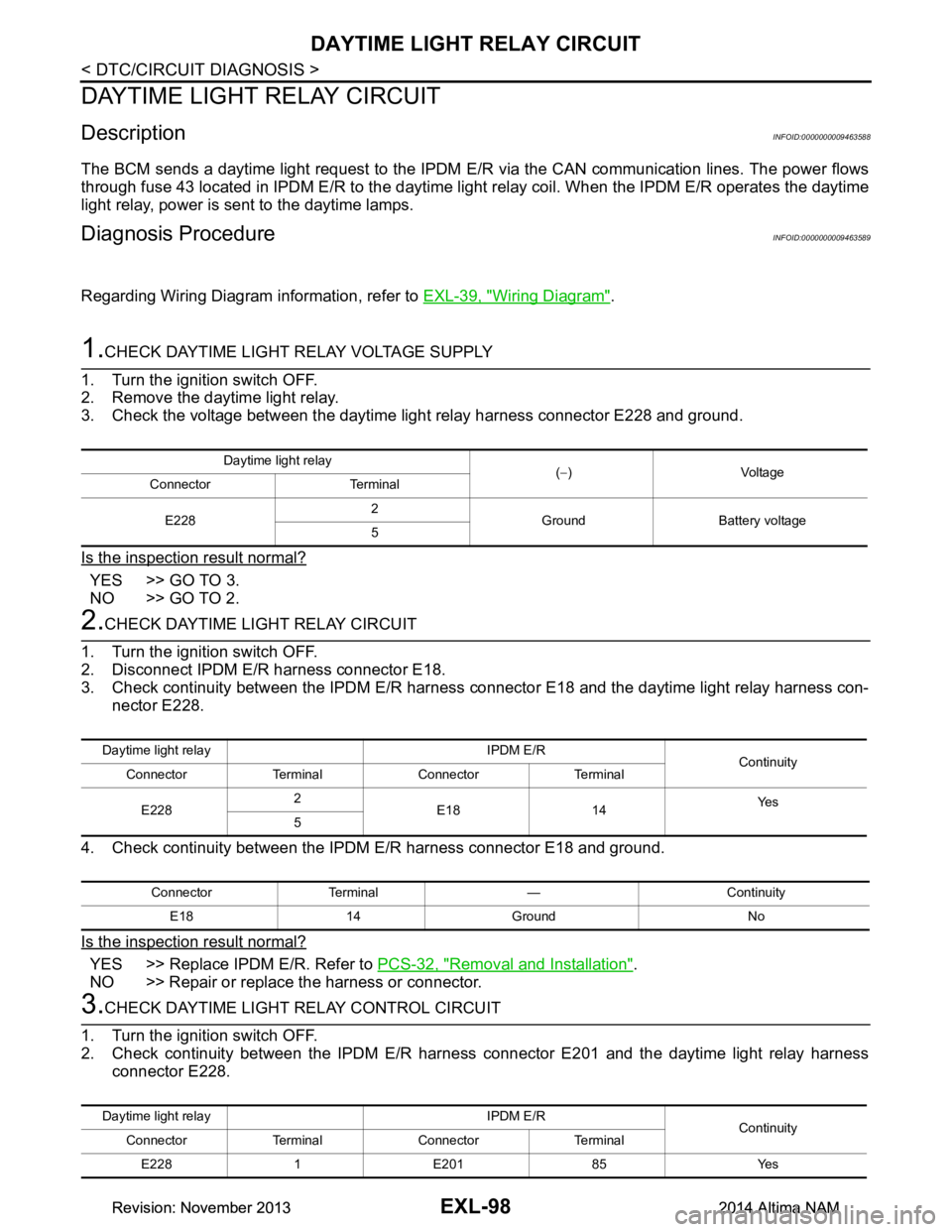
DescriptionINFOID:0000000009463588
The BCM sends a daytime light request to the IPDM E/R via the CAN communication lines. The power flows
through fuse 43 located in IPDM E/R to the daytime li ght relay coil. When the IPDM E/R operates the daytime
light relay, power is sent to the daytime lamps.
Diagnosis ProcedureINFOID:0000000009463589
Regarding Wiring Diagram information, refer to EXL-39, "Wiring Diagram".
1.CHECK DAYTIME LIGHT RELAY VOLTAGE SUPPLY
1. Turn the ignition switch OFF.
2. Remove the daytime light relay.
3. Check the voltage between the daytime light relay harness connector E228 and ground.
Is the inspection result normal?
YES >> GO TO 3.
NO >> GO TO 2.
2.CHECK DAYTIME LIGHT RELAY CIRCUIT
1. Turn the ignition switch OFF.
2. Disconnect IPDM E/R harness connector E18.
3. Check continuity between the IPDM E/R harness c onnector E18 and the daytime light relay harness con-
nector E228.
4. Check continuity between the IP DM E/R harness connector E18 and ground.
Is the inspection result normal?
YES >> Replace IPDM E/R. Refer to PCS-32, "Removal and Installation".
NO >> Repair or replace the harness or connector.
3.CHECK DAYTIME LIGHT RELAY CONTROL CIRCUIT
1. Turn the ignition switch OFF.
2. Check continuity between the IPDM E/R harness connector E201 and the daytime light relay harness
connector E228.
Daytime light relay (− )Voltage
Connector Terminal
E228 2
Ground Battery voltage
5
Daytime light relay IPDM E/R Continuity
Connector Terminal Connector Terminal
E228 2
E18 14 Ye s
5
Connector Terminal — Continuity
E18 14 Ground No
Daytime light relay IPDM E/R Continuity
Connector Terminal Connector Terminal
E228 1 E201 85 Yes
Revision: November 20132014 Altima NAMRevision: November 20132014 Altima NAM
Page 2367 of 4801
FRONT FOG LAMP CIRCUITEXL-101
< DTC/CIRCUIT DIAGNOSIS >
C
D E
F
G H
I
J
K
M A
B
EXL
N
O P
FRONT FOG LAMP CIRCUIT
DescriptionINFOID:0000000009463591
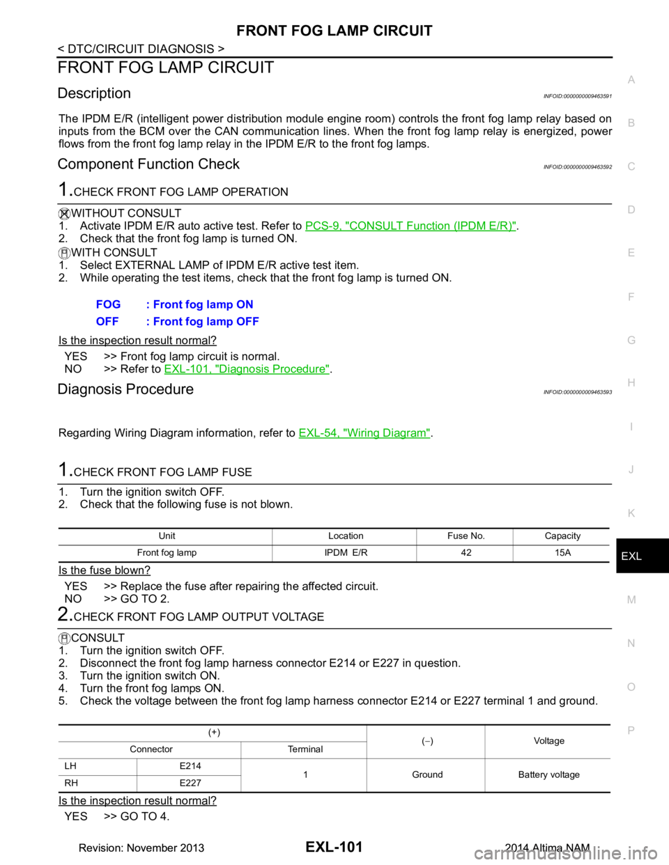
The IPDM E/R (intelligent power di stribution module engine room) controls the front fog lamp relay based on
inputs from the BCM over the CAN communication lines . When the front fog lamp relay is energized, power
flows from the front fog lamp relay in the IPDM E/R to the front fog lamps.
Component Function CheckINFOID:0000000009463592
1.CHECK FRONT FOG LAMP OPERATION
WITHOUT CONSULT
1. Activate IPDM E/R auto active test. Refer to PCS-9, "CONSULT Function (IPDM E/R)"
.
2. Check that the front fog lamp is turned ON.
WITH CONSULT
1. Select EXTERNAL LAMP of IP DM E/R active test item.
2. While operating the test items, check that the front fog lamp is turned ON.
Is the inspection result normal?
YES >> Front fog lamp circuit is normal.
NO >> Refer to EXL-101, "Diagnosis Procedure"
.
Diagnosis ProcedureINFOID:0000000009463593
Regarding Wiring Diagram information, refer to EXL-54, "Wiring Diagram".
1.CHECK FRONT FOG LAMP FUSE
1. Turn the ignition switch OFF.
2. Check that the following fuse is not blown.
Is the fuse blown?
YES >> Replace the fuse after repairing the affected circuit.
NO >> GO TO 2.
2.CHECK FRONT FOG LAMP OUTPUT VOLTAGE
CONSULT
1. Turn the ignition switch OFF.
2. Disconnect the front fog lamp harness connector E214 or E227 in question.
3. Turn the ignition switch ON.
4. Turn the front fog lamps ON.
5. Check the voltage between the front fog lamp harness connector E214 or E227 terminal 1 and ground.
Is the inspection result normal?
YES >> GO TO 4. FOG : Front fog lamp ON
OFF : Front fog lamp OFF
Unit Location Fuse No. Capacity
Front fog lamp IPDM E/R 42 15A
(+) (− )Voltage
Connector Terminal
LH E214 1 Ground Battery voltage
RH E227
Revision: November 20132014 Altima NAMRevision: November 20132014 Altima NAM
Page 2369 of 4801
PARKING LAMP CIRCUITEXL-103
< DTC/CIRCUIT DIAGNOSIS >
C
D E
F
G H
I
J
K
M A
B
EXL
N
O P
PARKING LAMP CIRCUIT
DescriptionINFOID:0000000009463594
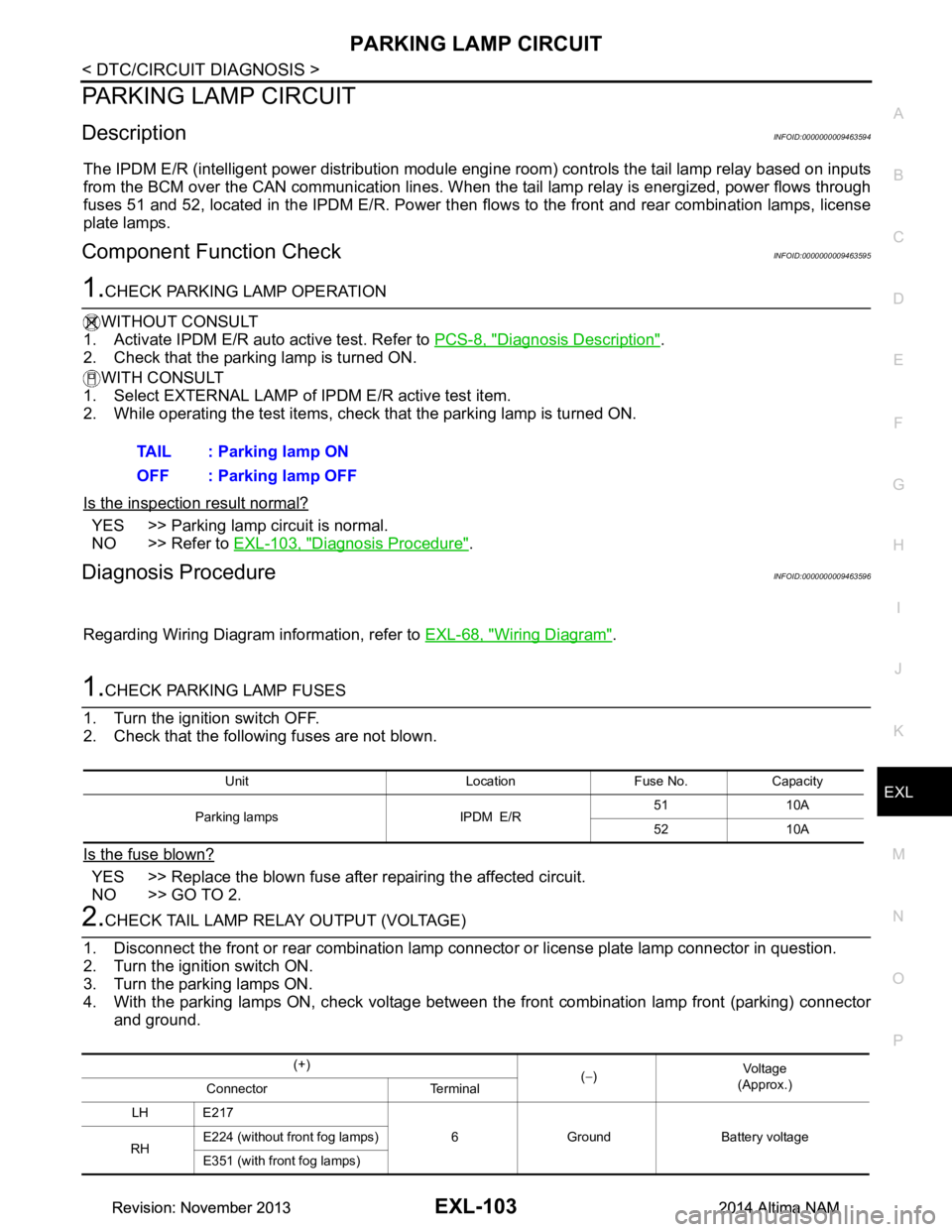
The IPDM E/R (intelligent power distribution module engi ne room) controls the tail lamp relay based on inputs
from the BCM over the CAN communication lines. When t he tail lamp relay is energized, power flows through
fuses 51 and 52, located in the IPDM E/R. Power then fl ows to the front and rear combination lamps, license
plate lamps.
Component Function CheckINFOID:0000000009463595
1.CHECK PARKING LAMP OPERATION
WITHOUT CONSULT
1. Activate IPDM E/R auto active test. Refer to PCS-8, "Diagnosis Description"
.
2. Check that the parking lamp is turned ON.
WITH CONSULT
1. Select EXTERNAL LAMP of IP DM E/R active test item.
2. While operating the test items, check that the parking lamp is turned ON.
Is the inspection result normal?
YES >> Parking lamp circuit is normal.
NO >> Refer to EXL-103, "Diagnosis Procedure"
.
Diagnosis ProcedureINFOID:0000000009463596
Regarding Wiring Diagram information, refer to EXL-68, "Wiring Diagram".
1.CHECK PARKING LAMP FUSES
1. Turn the ignition switch OFF.
2. Check that the following fuses are not blown.
Is the fuse blown?
YES >> Replace the blown fuse after repairing the affected circuit.
NO >> GO TO 2.
2.CHECK TAIL LAMP RELAY OUTPUT (VOLTAGE)
1. Disconnect the front or rear combination lamp connector or license plate lamp connector in question.
2. Turn the ignition switch ON.
3. Turn the parking lamps ON.
4. With the parking lamps ON, check voltage between t he front combination lamp front (parking) connector
and ground. TAIL : Parking lamp ON
OFF : Parking lamp OFF
Unit Location Fuse No. Capacity
Parking lamps IPDM E/R 51 10A
52 10A
(+) (− ) Vo l ta g e
(Approx.)
Connector Terminal
LH E217 6 Ground Battery voltage
RH E224 (without front fog lamps)
E351 (with front fog lamps)
Revision: November 20132014 Altima NAMRevision: November 20132014 Altima NAM