2014 NISSAN TEANA check oil
[x] Cancel search: check oilPage 4177 of 4801

STC-26
< DTC/CIRCUIT DIAGNOSIS >
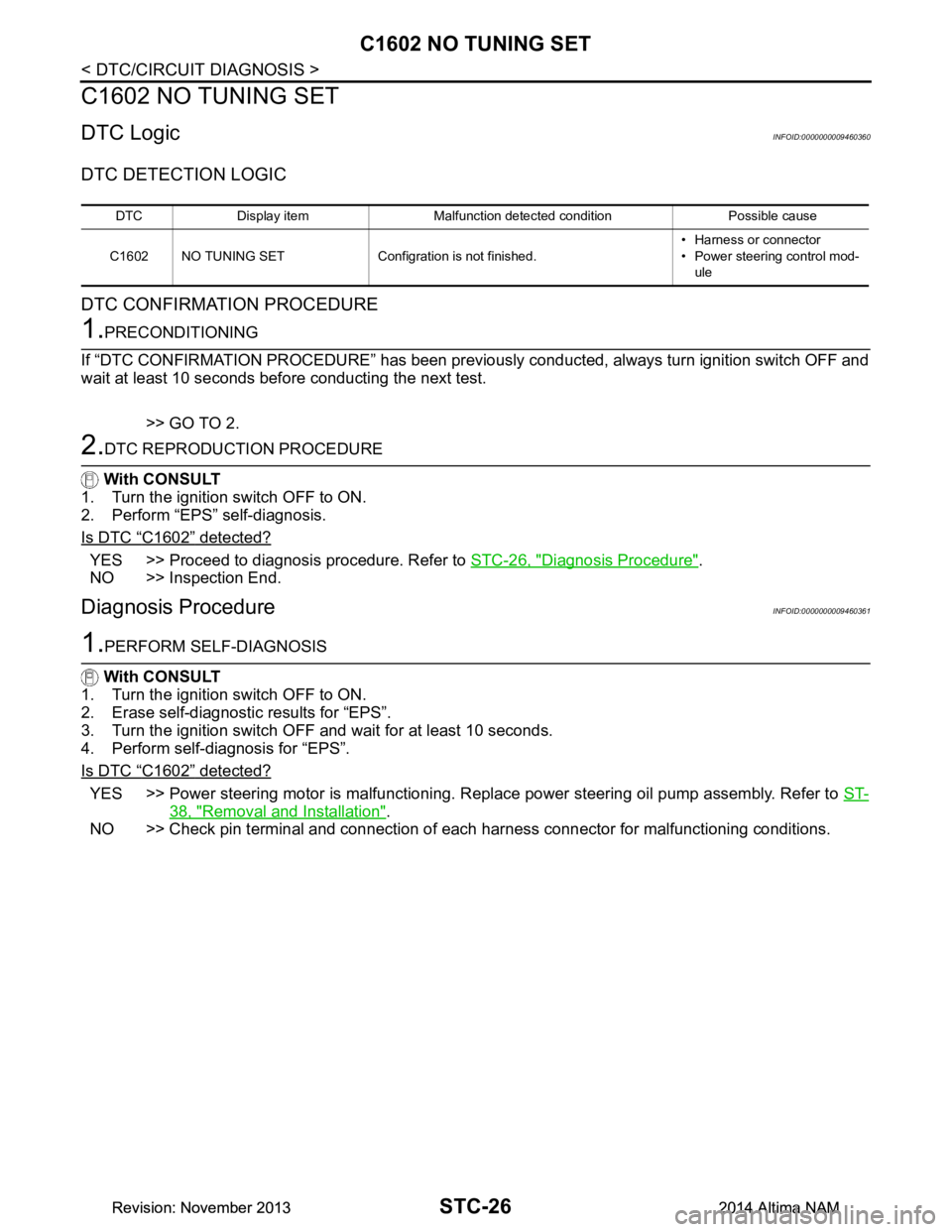
C1602 NO TUNING SET
C1602 NO TUNING SET
DTC LogicINFOID:0000000009460360
DTC DETECTION LOGIC
DTC CONFIRMATION PROCEDURE
1.PRECONDITIONING
If “DTC CONFIRMATION PROCEDURE” has been previously conducted, always turn ignition switch OFF and
wait at least 10 seconds before conducting the next test.
>> GO TO 2.
2.DTC REPRODUCTION PROCEDURE
With CONSULT
1. Turn the ignition switch OFF to ON.
2. Perform “EPS” self-diagnosis.
Is DTC
“C1602” detected?
YES >> Proceed to diagnosis procedure. Refer to STC-26, "Diagnosis Procedure".
NO >> Inspection End.
Diagnosis ProcedureINFOID:0000000009460361
1.PERFORM SELF-DIAGNOSIS
With CONSULT
1. Turn the ignition switch OFF to ON.
2. Erase self-diagnostic results for “EPS”.
3. Turn the ignition switch OFF and wait for at least 10 seconds.
4. Perform self-diagnosis for “EPS”.
Is DTC
“C1602” detected?
YES >> Power steering motor is malfunctioning. Replace power steering oil pump assembly. Refer to ST-
38, "Removal and Installation".
NO >> Check pin terminal and connection of each harness connector for malfunctioning conditions.
DTC Display item Malfunction detected condition Possible cause
C1602 NO TUNING SET Configration is not finished. • Harness or connector
• Power steering control mod-
ule
Revision: November 20132014 Altima NAMRevision: November 20132014 Altima NAM
Page 4178 of 4801

C1606 EPS MOTORSTC-27
< DTC/CIRCUIT DIAGNOSIS >
C
D E
F
H I
J
K L
M A
B
STC
N
O P
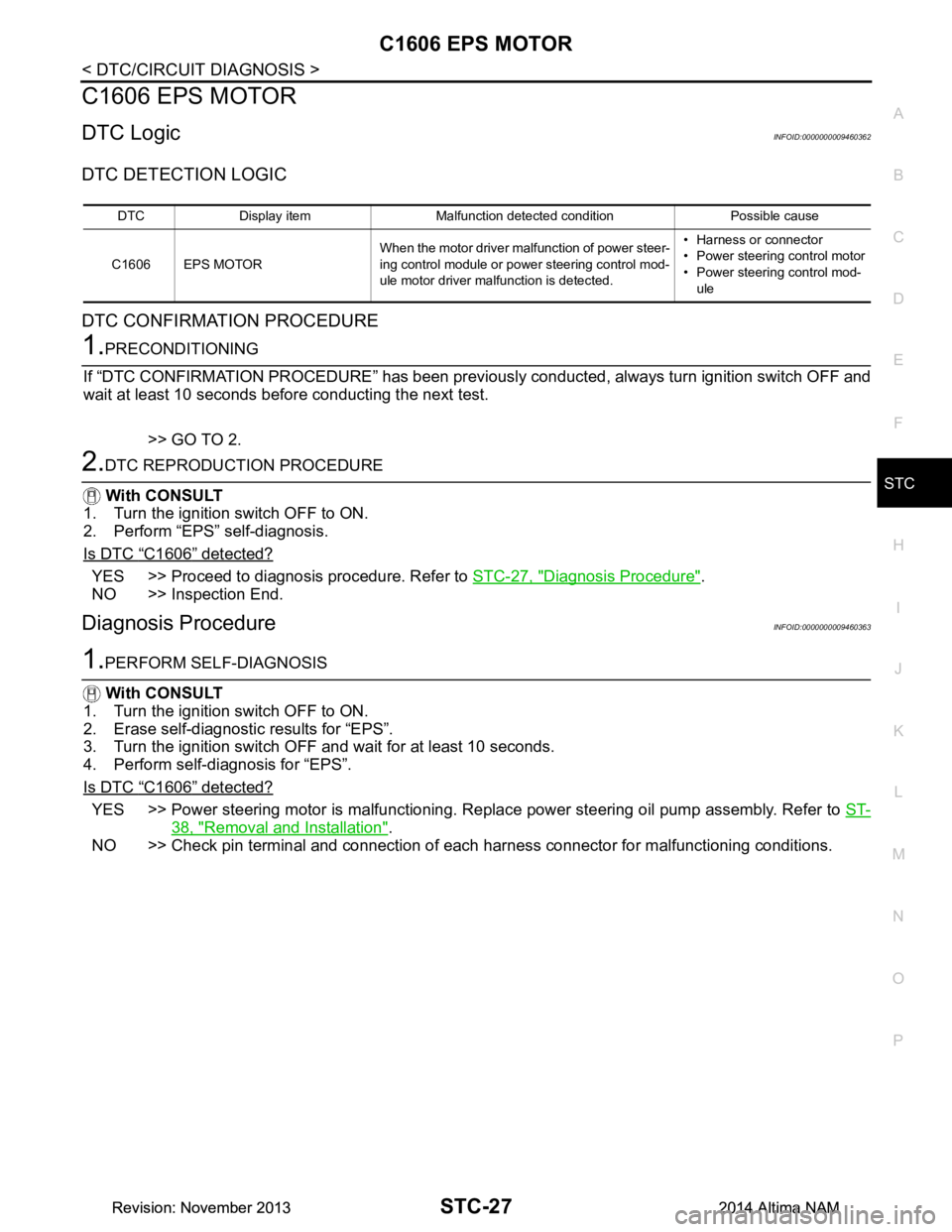
C1606 EPS MOTOR
DTC LogicINFOID:0000000009460362
DTC DETECTION LOGIC
DTC CONFIRMATION PROCEDURE
1.PRECONDITIONING
If “DTC CONFIRMATION PROCEDURE” has been previously conducted, always turn ignition switch OFF and
wait at least 10 seconds before conducting the next test.
>> GO TO 2.
2.DTC REPRODUCTION PROCEDURE
With CONSULT
1. Turn the ignition switch OFF to ON.
2. Perform “EPS” self-diagnosis.
Is DTC
“C1606” detected?
YES >> Proceed to diagnosis procedure. Refer to STC-27, "Diagnosis Procedure".
NO >> Inspection End.
Diagnosis ProcedureINFOID:0000000009460363
1.PERFORM SELF-DIAGNOSIS
With CONSULT
1. Turn the ignition switch OFF to ON.
2. Erase self-diagnostic results for “EPS”.
3. Turn the ignition switch OFF and wait for at least 10 seconds.
4. Perform self-diagnosis for “EPS”.
Is DTC
“C1606” detected?
YES >> Power steering motor is malfunctioning. Replace power steering oil pump assembly. Refer to ST-
38, "Removal and Installation".
NO >> Check pin terminal and connection of each harness connector for malfunctioning conditions.
DTC Display item Malfunction detected condition Possible cause
C1606 EPS MOTOR When the motor driver malfunction of power steer-
ing control module or power steering control mod-
ule motor driver malfunction is detected. • Harness or connector
• Power steering control motor
• Power steering control mod- ule
Revision: November 20132014 Altima NAMRevision: November 20132014 Altima NAM
Page 4179 of 4801

STC-28
< DTC/CIRCUIT DIAGNOSIS >
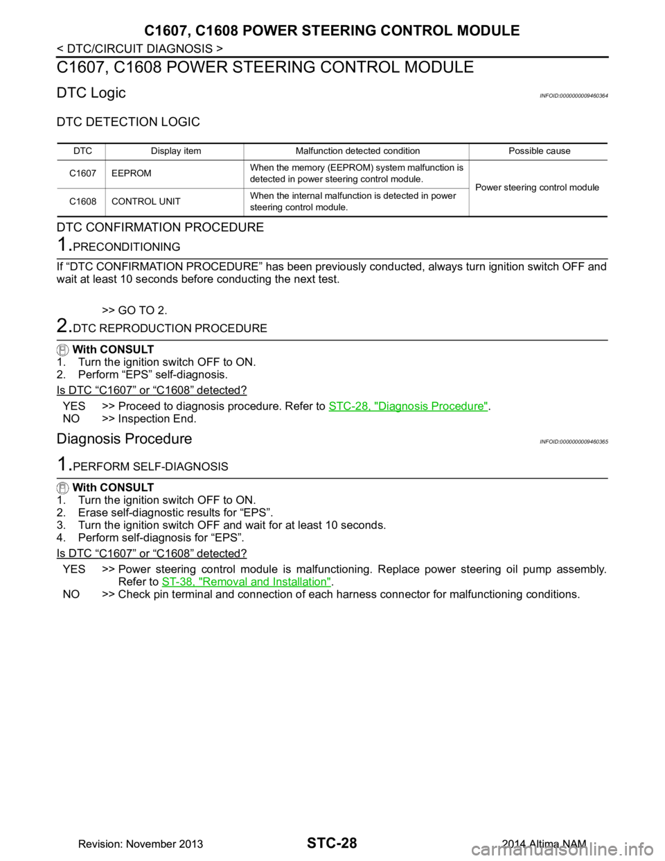
C1607, C1608 POWER STEERING CONTROL MODULE
C1607, C1608 POWER STEERING CONTROL MODULE
DTC LogicINFOID:0000000009460364
DTC DETECTION LOGIC
DTC CONFIRMATION PROCEDURE
1.PRECONDITIONING
If “DTC CONFIRMATION PROCEDURE” has been previously conducted, always turn ignition switch OFF and
wait at least 10 seconds before conducting the next test.
>> GO TO 2.
2.DTC REPRODUCTION PROCEDURE
With CONSULT
1. Turn the ignition switch OFF to ON.
2. Perform “EPS” self-diagnosis.
Is DTC
“C1607” or “C1608” detected?
YES >> Proceed to diagnosis procedure. Refer to STC-28, "Diagnosis Procedure".
NO >> Inspection End.
Diagnosis ProcedureINFOID:0000000009460365
1.PERFORM SELF-DIAGNOSIS
With CONSULT
1. Turn the ignition switch OFF to ON.
2. Erase self-diagnostic results for “EPS”.
3. Turn the ignition switch OFF and wait for at least 10 seconds.
4. Perform self-diagnosis for “EPS”.
Is DTC
“C1607” or “C1608” detected?
YES >> Power steering control module is malfunctioni ng. Replace power steering oil pump assembly.
Refer to ST-38, "Removal and Installation"
.
NO >> Check pin terminal and connection of each harness connector for malfunctioning conditions.
DTC Display item Malfunction detected condition Possible cause
C1607 EEPROM When the memo
ry (EEPROM) system malfunction is
detected in power steering control module. Power steering control module
C1608 CONTROL UNIT When the internal malfunction is detected in power
steering control module.
Revision: November 20132014 Altima NAMRevision: November 20132014 Altima NAM
Page 4182 of 4801

HYDRAULIC PUMP ELECTRIC POWER STEERING WARNING LAMP
STC-31
< DTC/CIRCUIT DIAGNOSIS >
C
D E
F
H I
J
K L
M A
B
STC
N
O P
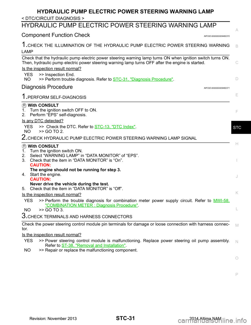
HYDRAULIC PUMP ELECTRIC PO WER STEERING WARNING LAMP
Component Function CheckINFOID:0000000009460370
1.CHECK THE ILLUMINATION OF THE HYDRAULIC PUMP ELECTRIC POWER STEERING WARNING
LAMP
Check that the hydraulic pump electric power steering warning lamp turns ON when ignition switch turns ON.
Then, hydraulic pump electric power steering warn ing lamp turns OFF after the engine is started.
Is the inspection result normal?
YES >> Inspection End.
NO >> Perform trouble diagnosis. Refer to STC-31, "Diagnosis Procedure"
.
Diagnosis ProcedureINFOID:0000000009460371
1.PERFORM SELF-DIAGNOSIS
With CONSULT
1. Turn the ignition switch OFF to ON.
2. Perform “EPS” self-diagnosis.
Is any DTC detected?
YES >> Check the DTC. Refer to STC-13, "DTC Index".
NO >> GO TO 2.
2.CHECK HYDRAULIC PUMP ELECTRIC PO WER STEERING WARNING LAMP SIGNAL
With CONSULT
1. Turn the ignition switch ON.
2. Select “WARNING LAMP” in “DATA MONITOR” of “EPS”.
3. Check that the item in “DATA MONITOR” is “On”. CAUTION:
The engine should not be running for step 3.
4. Start the engine. CAUTION:
Never drive the vehicle during the test.
5. Check that the item in “DATA MONITOR” is “Off”.
Is the inspection result normal?
YES >> Perform the trouble diagnosis for combinat ion meter power supply circuit. Refer to MWI-58,
"COMBINATION METER : Diagnosis Procedure".
NO >> GO TO 3.
3.CHECK TERMINALS AND HARNESS CONNECTORS
Check the power steering control module pin terminal s for damage or loose connection with harness connec-
tor.
Is the inspection result normal?
YES >> Power steering control module is malfuncti oning. Replace power steering oil pump assembly.
Refer to ST-38, "Removal and Installation"
.
NO >> Repair or replace the malfunctioning component.
Revision: November 20132014 Altima NAMRevision: November 20132014 Altima NAM
Page 4219 of 4801

TM-4
MAIN POWER SUPPLY AND GROUND CIR-
CUIT ................................................................ .
164
Diagnosis Procedure ........................................... ..164
OVERDRIVE CONTROL SWITCH ..................166
Component Function Check ................................ ..166
Diagnosis Procedure .............................................166
Component Inspection ...........................................167
OD OFF INDICATOR LAMP ............................168
Component Function Check ................................ ..168
Diagnosis Procedure .............................................168
SHIFT POSITION INDICATOR CIRCUIT ........169
Component Parts Function Inspection ................ ..169
Diagnosis Procedure .............................................169
SHIFT LOCK SYSTEM ................................... .170
Component Function Check ................................ ..170
Diagnosis Procedure .............................................170
Component Inspection (Shift Lock Solenoid) ........172
Component Inspection (Park Position Switch) ......172
Component Inspection (Stop Lamp Switch) ..........173
SYMPTOM DIAGNOSIS ............................174
CVT CONTROL SYSTEM ............................... .174
Symptom Table ................................................... ..174
PERIODIC MAINTENANCE ..................... ..178
CVT FLUID ...................................................... .178
Inspection ............................................................ ..178
REMOVAL AND INSTALLATION ..............179
CVT SHIFT SELECTOR ................................. .179
Exploded View ..................................................... ..179
Removal and Installation .......................................179
Inspection ..............................................................180
CONTROL CABLE ..........................................181
Exploded View ..................................................... ..181
Removal and Installation .......................................181
Inspection and Adjustment ....................................182
TCM ..................................................................183
Exploded View ..................................................... ..183
Removal and Installation .......................................183
Adjustment .............................................................184
AIR BREATHER HOSE ...................................185
Removal and Installation ..................................... ..185
CONTROL VALVE ...........................................186
Exploded View ..................................................... ..186
Removal and Installation .......................................187
Inspection ..............................................................191
INPUT SPEED SENSOR .................................192
Exploded View ..................................................... ..192
Removal and Installation .......................................192
Inspection and Adjustment ................................... .192
PRIMARY SPEED SENSOR .......................... ..194
Exploded View ..................................................... .194
Removal and Installation .......................................194
Inspection and Adjustment ................................... .194
OUTPUT SPEED SENSOR ..............................196
Exploded View ..................................................... .196
Removal and Installation .......................................196
Inspection and Adjustment ................................... .196
DIFFERENTIAL SIDE OIL SEAL .....................197
Exploded View ..................................................... .197
Removal and Installation .......................................197
Inspection and Adjustment ................................... .198
CVT OIL WARMER SYSTEM ...........................199
WATER HOSE ........................................................ .199
WATER HOSE : Exploded View ...........................199
WATER HOSE : Removal and Installation ...........199
WATER HOSE : Inspection ..................................201
CVT FLUID COOLER HOSE .................................. .201
CVT FLUID COOLER HOSE : Exploded View .....201
CVT FLUID COOLER HOSE : Removal and In-
stallation ............................................................... .
202
CVT FLUID COOLER HOSE : Inspection .............203
CVT OIL WARMER ................................................ .203
CVT OIL WARMER : Exploded View ....................203
CVT OIL WARMER : Removal and Installation ....203
CVT OIL WARMER : Inspection .......................... .204
PLUG ................................................................205
Description ........................................................... .205
Exploded View ......................................................205
Removal and Installation .......................................205
Inspection and Adjustment ................................... .205
UNIT REMOVAL AND INSTALLATION ...206
TRANSAXLE ASSEMBLY ............................. ..206
Exploded View ..................................................... .206
Removal and Installation .......................................206
Inspection and Adjustment ................................... .208
UNIT DISASSEMBLY AND ASSEMBLY ..209
TORQUE CONVERTER AND CONVERTER
HOUSING OIL SEAL ...................................... ..
209
Exploded View ..................................................... .209
Disassembly ..........................................................209
Assembly ..............................................................209
Inspection ..............................................................210
SERVICE DATA AND SPECIFICATIONS
(SDS) ............... ..........................................
212
SERVICE DATA AND SPECIFICATIONS
(SDS) .............................................................. ..
212
Revision: November 20132014 Altima NAMRevision: November 20132014 Altima NAM
Page 4225 of 4801
![NISSAN TEANA 2014 Service Manual
TM-10
< PRECAUTION >[CVT: RE0F10D]
PRECAUTIONS
General Precautions
INFOID:0000000009463957
• Turn ignition switch OFF an d disconnect the battery cable
from the negative terminal before connecting NISSAN TEANA 2014 Service Manual
TM-10
< PRECAUTION >[CVT: RE0F10D]
PRECAUTIONS
General Precautions
INFOID:0000000009463957
• Turn ignition switch OFF an d disconnect the battery cable
from the negative terminal before connecting](/manual-img/5/57390/w960_57390-4224.png)
TM-10
< PRECAUTION >[CVT: RE0F10D]
PRECAUTIONS
General Precautions
INFOID:0000000009463957
• Turn ignition switch OFF an d disconnect the battery cable
from the negative terminal before connecting or disconnect-
ing the CVT assembly harness connector. Because battery
voltage is applied to TCM even if ignition switch is turned
OFF.
• When connecting or disconnect ing pin connectors into or
from TCM, do not damage pin terminals (bend or break).
Check that there are not any bends or breaks on TCM pin ter-
minal, when connect ing pin connectors.
• Perform TCM input/output si gnal inspection and check
whether TCM functions normally or not before replacing TCM.
Refer to TM-49, "Reference Value"
.
• Perform “DTC (Diagnostic Trouble Code) CONFIRMATION
PROCEDURE”.
If the repair is completed DTC should not be displayed in the
“DTC CONFIRMATION PROCEDURE”.
• Always use the specified brand of CVT fluid. Refer to MA-11, "FOR USA AND CANADA : Fluids and Lubri-
cants".
• Use lint-free paper not cloth rags during work.
• Dispose of the waste oil using the methods prescribed by law, ordinance, etc. after replacing the CVT fluid.
SEF289H
AAT470A
MEF040DA
JSBIA1315ZZ
Revision: November 20132014 Altima NAMRevision: November 20132014 Altima NAM
Page 4235 of 4801
![NISSAN TEANA 2014 Service Manual
TM-20
< SYSTEM DESCRIPTION >[CVT: RE0F10D]
COMPONENT PARTS
• The principle of the linear solenoid valve utilizes the fa
ct that the force pressing on the valve spool installed
inside the coil incre NISSAN TEANA 2014 Service Manual
TM-20
< SYSTEM DESCRIPTION >[CVT: RE0F10D]
COMPONENT PARTS
• The principle of the linear solenoid valve utilizes the fa
ct that the force pressing on the valve spool installed
inside the coil incre](/manual-img/5/57390/w960_57390-4234.png)
TM-20
< SYSTEM DESCRIPTION >[CVT: RE0F10D]
COMPONENT PARTS
• The principle of the linear solenoid valve utilizes the fa
ct that the force pressing on the valve spool installed
inside the coil increases nearly in proportion to the current . This allows it to produce a fluid pressure that is
proportional to this pressing force.
• The N/L (normal low) type does not produce hydr aulic control when the coil is not energized.
CVT CONTROL SYSTEM : Line Pressure Solenoid ValveINFOID:0000000009463975
• The line pressure solenoid valve is installed to control valve.
• The line pressure solenoid valve controls the pressure regulator valve. For information about the pressure
regulator valve, refer to TM-27, "TRANSAXLE : Component Description"
.
• The line pressure solenoid valve uses the linear solenoid valve [N/H (normal high) type]. NOTE:
• The principle of the linear solenoid valve utilizes the fa ct that the force pressing on the valve spool installed
inside the coil increases nearly in proportion to the current . This allows it to produce a fluid pressure that is
proportional to this pressing force.
• The N/H (normal high) produces hydraulic control when the coil is not energized.
CVT CONTROL SYSTEM : Overdrive Control SwitchINFOID:0000000009463976
• The overdrive control switch is inst alled to the selector lever knob.
• If the overdrive control switch is pressed when the O/D OFF indicator lamp on the combination meter is not
lit, the status changes to overdrive OFF and the O/D OFF indicator lamp illuminates.
• If the overdrive control switch is pressed when the O/ D OFF indicator lamp on the combination meter is lit,
the overdrive OFF status is canceled and the O/D OFF indicator lamp turns off.
CVT CONTROL SYSTEM : O/D OFF Indicator LampINFOID:0000000009463977
• O/D OFF indicator lamp is positioned on the combination meter.
• The O/D OFF indicator lamp illuminates when the overdrive function is deactivated (O/D OFF).
• For checking the bulb, this lamp turns on for a cert ain period of time when the ignition switch turns ON,
andthen turns off.
CVT CONTROL SYSTEM : Sh ift Position IndicatorINFOID:0000000009463978
TCM transmits shift position signal to combination meter via CAN communication. The actual shift position is
displayed on combination meter according to the signal.
SHIFT LOCK SYSTEM
Condition (status) O/D OFF indicator lamp
Ignition switch OFF. OFF
Ignition switch ON. ON (Approx. 2 seconds)
Overdrive control switch is pressed when the selector lever is in
the D position and the O/D OFF indicator lamp is OFF (when sys-
tem is normal). ON
Overdrive control switch is pressed when the selector lever is in
the D position and the O/D OFF indicator lamp is ON. OFF
Selector lever is shifted from the D position to another position-
when the O/D OFF indicator lamp is ON. OFF
Revision: November 20132014 Altima NAMRevision: November 20132014 Altima NAM
Page 4263 of 4801
![NISSAN TEANA 2014 Service Manual
TM-48
< SYSTEM DESCRIPTION >[CVT: RE0F10D]
DIAGNOSIS SYSTEM (TCM)
*: Not applicable but displayed.
WORK SUPPORT
Engine brake adjustment
Check the degradation level of the CVT fluid.
ACTIVE TEST
NORM NISSAN TEANA 2014 Service Manual
TM-48
< SYSTEM DESCRIPTION >[CVT: RE0F10D]
DIAGNOSIS SYSTEM (TCM)
*: Not applicable but displayed.
WORK SUPPORT
Engine brake adjustment
Check the degradation level of the CVT fluid.
ACTIVE TEST
NORM](/manual-img/5/57390/w960_57390-4262.png)
TM-48
< SYSTEM DESCRIPTION >[CVT: RE0F10D]
DIAGNOSIS SYSTEM (TCM)
*: Not applicable but displayed.
WORK SUPPORT
Engine brake adjustment
Check the degradation level of the CVT fluid.
ACTIVE TEST
NORMAL MODE* (On/Off) D
isplays whether it is the NORMAL mode.
SPORT MODE* (On/Off) Displays whether it is the SPORT mode.
AIR BLDING STATE* (INCOMP/
COMP) Displays the status of “E
LECTRIC O.P. AIR BLEEDING”
in “Work Support”.
ELECTRIC OP DUTY* (%) Displays the command signal value (duty) of the electric
oil pump transmitted from TCM.
E-OP DUTY MON* (%) Monitors the status signal value (duty) transmitted from
the electric oil pump and displays the monitored value.
ELECTRIC OP RELAY* (On/Off) Displays the command status from TCM to the electric oil
pump relay.
E-OP RELAY MON* (On/Off) Monitors the command status from TCM to the oil pump
relay and displays the monitored value.
Monitored item (Unit)
Monitor item selection
Remarks
ECU IN-
PUT SIG-
NALS MAIN SIG-
NALS
Item name Description
CONFORM CVTF DETERIORTN Checks the degradation level of the CVT fluid under severe conditions.
ERASE MEMORY DATA Performs “erasing of the calibration data” and “erasing of the learned value” at the
same time.
G SENSOR CALIBRATION Compensates the G sensor.
ERASE LEARNING VALUE Erases lear ning value memorized by TCM.
ENGINE BRAKE ADJ. Although there is no malfunction on the transaxle and the CVT system, if a cus-
tomer make a complaint like “I do not feel comfortable with automatic operation of
the engine brake on downhill”, the engine brake may be cancelled with “engine
brake adjustment”.
ERASE CALIBRATION DATA Erases cali bration data memorized by TCM.
WRITE IP CHARA - REPLACEMENT AT/CVT Writes IP characteristics when transaxle assembly is replaced.
READ IP CHARA - REPLACEMENT TCM Reads IP characteristics when TCM is replaced.
WRITE IP CHARA - REPLACEMENT TCM Writes IP characteristics when TCM is replaced.
ENGINE BRAKE LEVEL
ON : Turn ON the engine brake control.
OFF : Turn OFF the engine brake control.
CVTF degradation level data
210,000 or more : Replacement of the CVT fluid is required.
Less than 210,000 : Replacement of the CVT fluid is not required.
Item name Description
CVT OIL COOLER FAN CIRCUIT Checks the operation of CVT oil cooler fan relay.
Revision: November 20132014 Altima NAMRevision: November 20132014 Altima NAM