2014 NISSAN TEANA check oil
[x] Cancel search: check oilPage 3221 of 4801

CHASSIS AND BODY MAINTENANCEMA-37
< PERIODIC MAINTENANCE >
C
D E
F
G H
I
J
K L
M B
MA
N
O A
34. Select “Data Monitor” in “TRANSMISSION” using CONSULT.
35. Select “CONFORM CVTF DETERIORTN”.
36. Select “Erase”.
37. Stop the engine.
CVT FLUID : AdjustmentINFOID:0000000009464573
CAUTION:
• During adjustment of the CVT fluid level, check CO NSULT so that the oil temperature may be main-
tained from 35 to 45 °C (95 to 113 °F).
• During adjustment of the CVT fluid level, check that the engine speed is maintaining 500 rpm.
• Use caution when looking into the drain hole as there is a risk of dripping fluid entering the eye.
1. Check that the selector lever is in the “P ” position, then completely engage the parking brake.
2. Start the engine.
3. Adjust the CVT fluid temperature to be approximately 40 °C (104 °F).
NOTE:
The CVT fluid is largely affected by temperature. Therefore be sure to use CONSULT and check the
“FLUID TEMP” under “TRA NSMISSION” in “Data Monitor” while adjusting.
4. While depressing the brake pedal, shift the selector leve r to the entire position from “P” to “DS”, and shift it
to the “P” position.
NOTE:
Hold the lever at each position for 5 seconds.
5. Lift up the vehicle.
6. Check that there is no CVT fluid leakage.
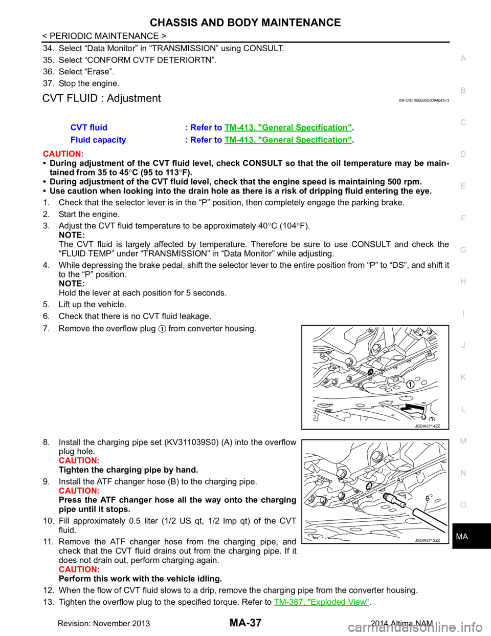
7. Remove the overflow plug from converter housing.
8. Install the charging pipe set (KV311039S0) (A) into the overflow plug hole.
CAUTION:
Tighten the charging pipe by hand.
9. Install the ATF changer hose (B) to the charging pipe. CAUTION:
Press the ATF changer hose all the way onto the charging
pipe until it stops.
10. Fill approximately 0.5 liter (1/2 US qt, 1/2 lmp qt) of the CVT
fluid.
11. Remove the ATF changer hose from the charging pipe, and check that the CVT fluid drains out from the charging pipe. If it
does not drain out, perform charging again.
CAUTION:
Perform this work with the vehicle idling.
12. When the flow of CVT fluid slows to a drip, re move the charging pipe from the converter housing.
13. Tighten the overflow plug to the specified torque. Refer to TM-387, "Exploded View"
.
CVT fluid : Refer to
TM-413, "General Specification"
.
Fluid capacity : Refer to TM-413, "General Specification"
.
JSDIA3714ZZ
JSDIA3713ZZ
Revision: November 20132014 Altima NAM
Page 3228 of 4801

MA-44
< PERIODIC MAINTENANCE >
CHASSIS AND BODY MAINTENANCE
POWER STEERING FLUID AND LINES : Inspection
INFOID:0000000009464588
FLUID LEVEL
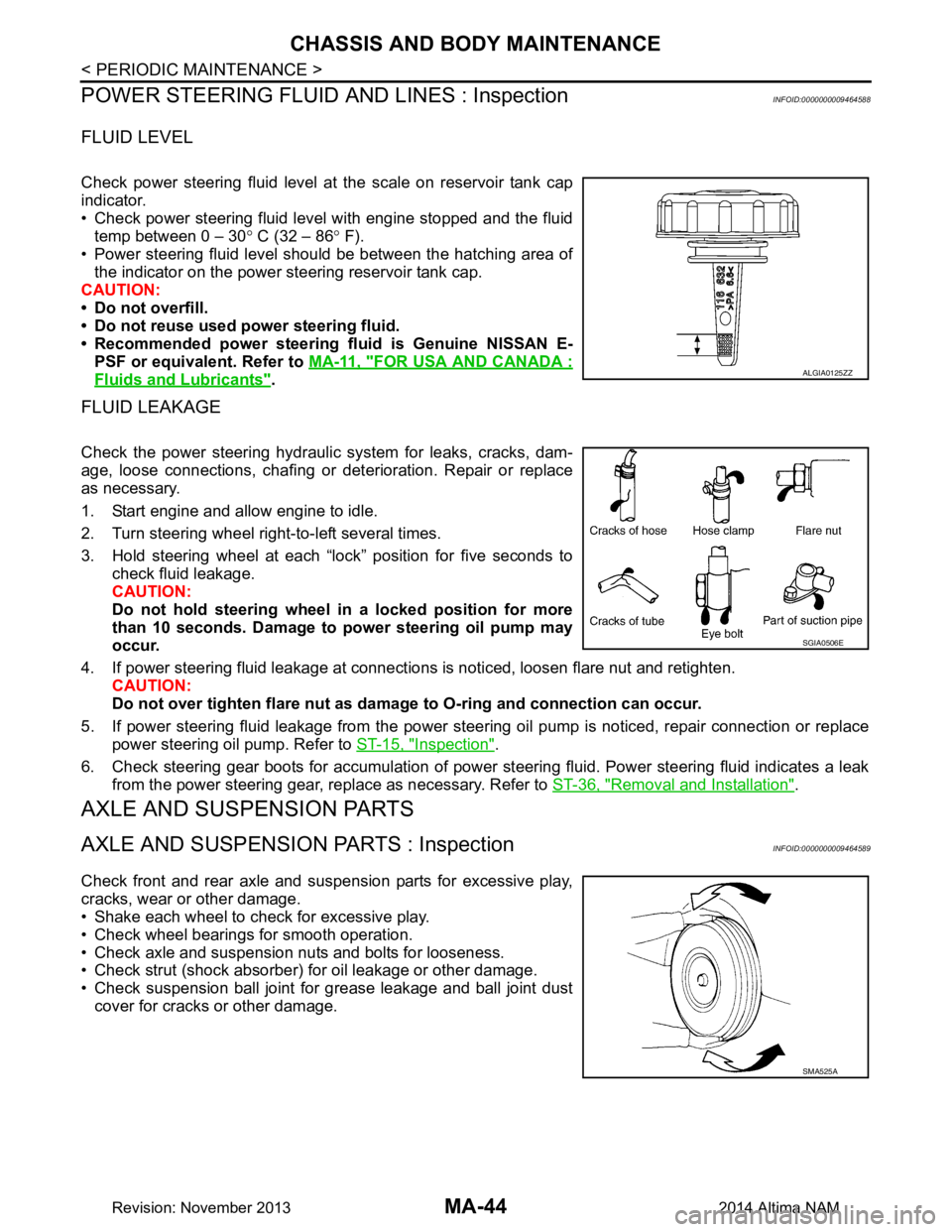
Check power steering fluid level at the scale on reservoir tank cap
indicator.
• Check power steering fluid level with engine stopped and the fluid temp between 0 – 30 ° C (32 – 86 ° F).
• Power steering fluid level should be between the hatching area of the indicator on the power steering reservoir tank cap.
CAUTION:
• Do not overfill.
• Do not reuse used power steering fluid.
• Recommended power steering fluid is Genuine NISSAN E-
PSF or equivalent. Refer to MA-11, "FOR USA AND CANADA :
Fluids and Lubricants".
FLUID LEAKAGE
Check the power steering hydraulic system for leaks, cracks, dam-
age, loose connections, chafing or det erioration. Repair or replace
as necessary.
1. Start engine and allow engine to idle.
2. Turn steering wheel right-to-left several times.
3. Hold steering wheel at each “lock” position for five seconds to check fluid leakage.
CAUTION:
Do not hold steering wheel in a locked position for more
than 10 seconds. Damage to power steering oil pump may
occur.
4. If power steering fluid leakage at connections is noticed, loosen flare nut and retighten.
CAUTION:
Do not over tighten flare nut as damage to O-ring and connection can occur.
5. If power steering fluid leakage from the power steer ing oil pump is noticed, repair connection or replace
power steering oil pump. Refer to ST-15, "Inspection"
.
6. Check steering gear boots for accumulation of power steering fluid. Power steering fluid indicates a leak from the power steering gear, replace as necessary. Refer to ST-36, "Removal and Installation"
.
AXLE AND SUSPENSION PARTS
AXLE AND SUSPENSION PARTS : InspectionINFOID:0000000009464589
Check front and rear axle and suspension parts for excessive play,
cracks, wear or other damage.
• Shake each wheel to check for excessive play.
• Check wheel bearings for smooth operation.
• Check axle and suspension nuts and bolts for looseness.
• Check strut (shock absorber) for oil leakage or other damage.
• Check suspension ball joint for grease leakage and ball joint dust cover for cracks or other damage.
ALGIA0125ZZ
SGIA0506E
SMA525A
Revision: November 20132014 Altima NAM
Page 3230 of 4801

MA-46
< PERIODIC MAINTENANCE >
CHASSIS AND BODY MAINTENANCE
Seat belt pre-tensioner should be replaced even if the seat belts are not in use during a frontal colli-
sion where the driver and passenger air bags are deployed.
• If any component of seat belt assembl y is questionable, do not repair.
Replace as seat belt assembly.
• If webbing is cut, frayed, or damaged, replace seat belt assembly.
• Do not oil tongue and buckle.
• Use only a Genuine NISSAN seat belt assembly.
For details, refer to SB-5, "Inspection"
in the SB section.
• Check anchors for loose mounting.
• Check belts for damage.
• Check retractor for smooth operation.
• Check function of buckles and tongues when buckled and released.
Revision: November 20132014 Altima NAM
Page 3232 of 4801

MIR-2
< PRECAUTION >
PRECAUTIONS
PRECAUTION
PRECAUTIONS
Precaution for Supplemental Restraint System (SRS) "AIR BAG" and "SEAT BELT
PRE-TENSIONER"
INFOID:0000000009951574
The Supplemental Restraint System such as “A IR BAG” and “SEAT BELT PRE-TENSIONER”, used along
with a front seat belt, helps to reduce the risk or severi ty of injury to the driver and front passenger for certain
types of collision. Information necessary to service the system safely is included in the SR and SB section of
this Service Manual.
WARNING:
• To avoid rendering the SRS inopera tive, which could increase the risk of personal injury or death in
the event of a collision which would result in air bag inflation, all maintenance must be performed by
an authorized NISS AN/INFINITI dealer.
• Improper maintenance, including in correct removal and installation of the SRS, can lead to personal
injury caused by unintent ional activation of the system. For re moval of Spiral Cable and Air Bag
Module, see the SR section.
• Do not use electrical test equipmen t on any circuit related to the SRS unless instructed to in this
Service Manual. SRS wiring harn esses can be identified by yellow and/or orange harnesses or har-
ness connectors.
PRECAUTIONS WHEN USING POWER TOOLS (AIR OR ELECTRIC) AND HAMMERS
WARNING:
• When working near the Airbag Diagnosis Sensor Unit or other Airbag System sensors with the Igni-
tion ON or engine running, DO NOT use air or electri c power tools or strike near the sensor(s) with a
hammer. Heavy vibration could activate the sensor( s) and deploy the air bag(s), possibly causing
serious injury.
• When using air or electric power tools or hammers , always switch the Ignition OFF, disconnect the
battery and wait at least three minutes before performing any service.
Precaution for WorkINFOID:0000000009463520
• When removing or disassembling each component, be careful not to damage or deform it. If a component may be subject to interference, be sure to protect it with a shop cloth.
• When removing (disengaging) components with a screwdriver or similar tool, be sure to wrap the component with a shop cloth or vinyl tape to protect it.
• Protect the removed parts with a s hop cloth and prevent them from being dropped.
• Replace a deformed or damaged clip.
• If a part is specified as a non-reusable part, always replace it with a new one.
• Be sure to tighten bolts and nuts securely to the specified torque.
• After installation is complete, be sure to check that each part works properly.
• Follow the steps below to clean components:
- Water soluble dirt:
• Dip a soft cloth into lukewarm water, wring the water out of the cloth and wipe the dirty area.
• Then rub with a soft, dry cloth.
- Oily dirt:
• Dip a soft cloth into lukewarm water with mild detergent (concentration: within 2 to 3%) and wipe the dirty area.
• Then dip a cloth into fresh water, wring the water out of the cloth and wipe the detergent off.
• Then rub with a soft, dry cloth.
- Do not use organic solvent such as thinner, benzene, alcohol or gasoline.
- For genuine leather seats, use a genuine leather seat cleaner.
Revision: November 20132014 Altima NAMRevision: November 20132014 Altima NAM
Page 3257 of 4801

MWI-2
Wiring Diagram .......................................................30
METER ...............................................................32
Wiring Diagram .................................................... ...32
BASIC INSPECTION ...................................51
DIAGNOSIS AND REPAIR WORKFLOW ...... ...51
Work flow ............................................................. ...51
DTC/CIRCUIT DIAGNOSIS ...................... ...53
U1000 CAN COMM CIRCUIT ......................... ...53
DTC Logic ............................................................ ...53
Diagnosis Procedure .............................................53
U1010 CONTROL UNIT (CAN) .........................54
Description ........................................................... ...54
DTC Logic ...............................................................54
Diagnosis Procedure ..............................................54
B2205 VEHICLE SPEED ...................................55
Description ........................................................... ...55
DTC Logic ...............................................................55
Diagnosis Procedure .............................................55
B2267 ENGINE SPEED .....................................56
Description ........................................................... ...56
DTC Logic ...............................................................56
Diagnosis Procedure ..............................................56
B2268 WATER TEMP ........................................57
Description ........................................................... ...57
DTC Logic ...............................................................57
Diagnosis Procedure ..............................................57
POWER SUPPLY AND GROUND CIRCUIT .....58
COMBINATION METER ........................................ ...58
COMBINATION METER : Diagnosis Procedure ....58
BCM (BODY CONTROL MODULE) ...................... ...58
BCM (BODY CONTROL MODULE) : Diagnosis
Procedure ............................................................ ...
58
IPDM E/R (INTELLIGENT POWER DISTRIBU-
TION MODULE ENGINE ROOM) .......................... ...
59
IPDM E/R (INTELLIGENT POWER DISTRIBU-
TION MODULE ENGINE ROOM) : Diagnosis Pro-
cedure .................................................................. ...
59
FUEL LEVEL SENSOR SIGNAL CIRCUIT .......61
Description ........................................................... ...61
Component Function Check ...................................61
Diagnosis Procedure .............................................61
Component Inspection ............................................62
PARKING BRAKE SWITCH SIGNAL CIR-
CUIT ................................................................ ...
63
Description ........................................................... ...63
Component Function Check ...................................63
Diagnosis Procedure ..............................................63
Component Inspection ......................................... ...63
WASHER FLUID LEVEL SWITCH CIRCUIT ....64
Description ........................................................... ...64
Diagnosis Procedure ...............................................64
Component Inspection ............................................64
AMBIENT SENSOR SIGNAL CIRCUIT ............66
Description ........................................................... ...66
Component Function Check ...................................66
Diagnosis Procedure ...............................................66
Component Inspection ............................................67
METER CONTROL SWITCH SIGNAL CIR-
CUIT ................................................................ ...
68
Diagnosis Procedure ............................................ ...68
Component Inspection ............................................69
STEERING SWITCH ..........................................70
Description ........................................................... ...70
Diagnosis Procedure ...............................................70
Component Inspection ............................................70
SYMPTOM DIAGNOSIS ............................72
THE FUEL GAUGE INDICATOR DOES NOT
OPERATE ....................................................... ...
72
Description ........................................................... ...72
Diagnosis Procedure ...............................................72
THE METER CONTROL SWITCH IS INOPER-
ATIVE .............................................................. ...
73
Description ........................................................... ...73
Diagnosis Procedure ...............................................73
THE OIL PRESSURE WARNING CONTIN-
UES DISPLAYING, OR DOES NOT DISPLAY ...
74
Description ........................................................... ...74
Diagnosis Procedure ...............................................74
THE PARKING BRAKE RELEASE WARNING
CONTINUES DISPLAYING, OR DOES NOT
DISPLAY ......................................................... ...
75
Description ........................................................... ...75
Diagnosis Procedure ...............................................75
THE LOW WASHER FLUID WARNING CON-
TINUES DISPLAYING, or DOES NOT DIS-
PLAY ............................................................... ...
76
Description ........................................................... ...76
Diagnosis Procedure ...............................................76
THE DOOR OPEN WARNING CONTINUES
DISPLAYING, OR DOES NOT DISPLAY ...... ...
77
Description ........................................................... ...77
Diagnosis Procedure ...............................................77
THE TRUNK OPEN WARNING CONTINUES
DISPLAYING, OR DOES NOT DISPLAY ...... ...
78
Description ........................................................... ...78
Diagnosis Procedure ...............................................78
Revision: November 20132014 Altima NAMRevision: November 20132014 Altima NAM
Page 3271 of 4801

MWI-16
< SYSTEM DESCRIPTION >
SYSTEM
The LOOSE FUEL CAP message will display in the information display when the fuel-filler cap is not tightened
correctly. The message will turn off as soon as the EC M detects the fuel-filler cap is properly tightened. The
ECM provides a loose fuel cap signal to the combination meter via CAN communication.
LOW TIRE PRESSURE WARNING
This warning appears when the BCM detects low inflati on pressure or a system malfunction. The BCM sends
a signal to the combination meter via CAN communication to illuminate the low tire pressure warning lamp. In
addition, a warning message will be displayed in the vehicle information display.
DOOR OPEN WARNING
This warning appears when the ignition switch is ON and the door is open. The BCM receives a door switch
signal from the door open door switch. The BCM sends t he door switch signal to the combination meter via
CAN communication lines.
TRUNK OPEN WARNING
This warning appears when the ignition switch is ON and the trunk is opened. The BCM receives a trunk lamp
switch signal from the trunk lamp switch. The BCM s ends the trunk lamp switch signal to the combination
meter via CAN communication.
LOW FUEL WARNING
This warning appears when the fuel level in the fuel tank is less than approximately 4 US gal (15 L, 3.3 Imp
gal). A variable resistor signal is supplied to the combi nation meter from the fuel level sensor unit to determine
the amount of fuel in the fuel tank.
LOW WINDSHIELD WASHER FLUID WARNING
When the windshield washer fluid level is low, the was her fluid level switch provides a ground signal to the
combination meter and the warning is displayed. Once fluid is added, the switch opens and the warning is no
longer displayed.
RELEASE PARKING BRAKE WARNING
When the parking brake is applied, the parking brake switch provides a ground signal to the combination
meter. When the vehicle speed is greater than 4 MPH (7 km/h), the message is displayed and the warning
chime sounds.
SHIFT POSITION INDICATOR
Displays the position of the shift selector based on signals received from TCM via CAN communication.
LOW OIL PRESSURE WARNING
The low oil pressure warning appears in the information display when the combination meter receives a low
engine oil pressure signal from the ECM via CAN communication.
WARNING CHECK INDICATION
The combination meter can cause an interrupt on the information display to indicate a warning, based on sig-
nals received from each unit and switch.
Refer to Owner’s Manual for additional information display items.
COMPASS
COMPASS : DescriptionINFOID:0000000009461691
DESCRIPTION
With the ignition switch in the ON position, and the mode (N) switch
ON, the compass display will indicate the direction the vehicle is
heading.
Vehicle direction is displayed as follows:
• N: north
• E: east
• S: south
•W: west
LKIA0447E
Revision: November 20132014 Altima NAMRevision: November 20132014 Altima NAM
Page 3329 of 4801

MWI-74
< SYMPTOM DIAGNOSIS >
THE OIL PRESSURE WARNING CONTINUES DISPLAYING, OR DOES NOT DIS-
PLAY
THE OIL PRESSURE WARNING CONT INUES DISPLAYING, OR DOES
NOT DISPLAY
DescriptionINFOID:0000000009461742
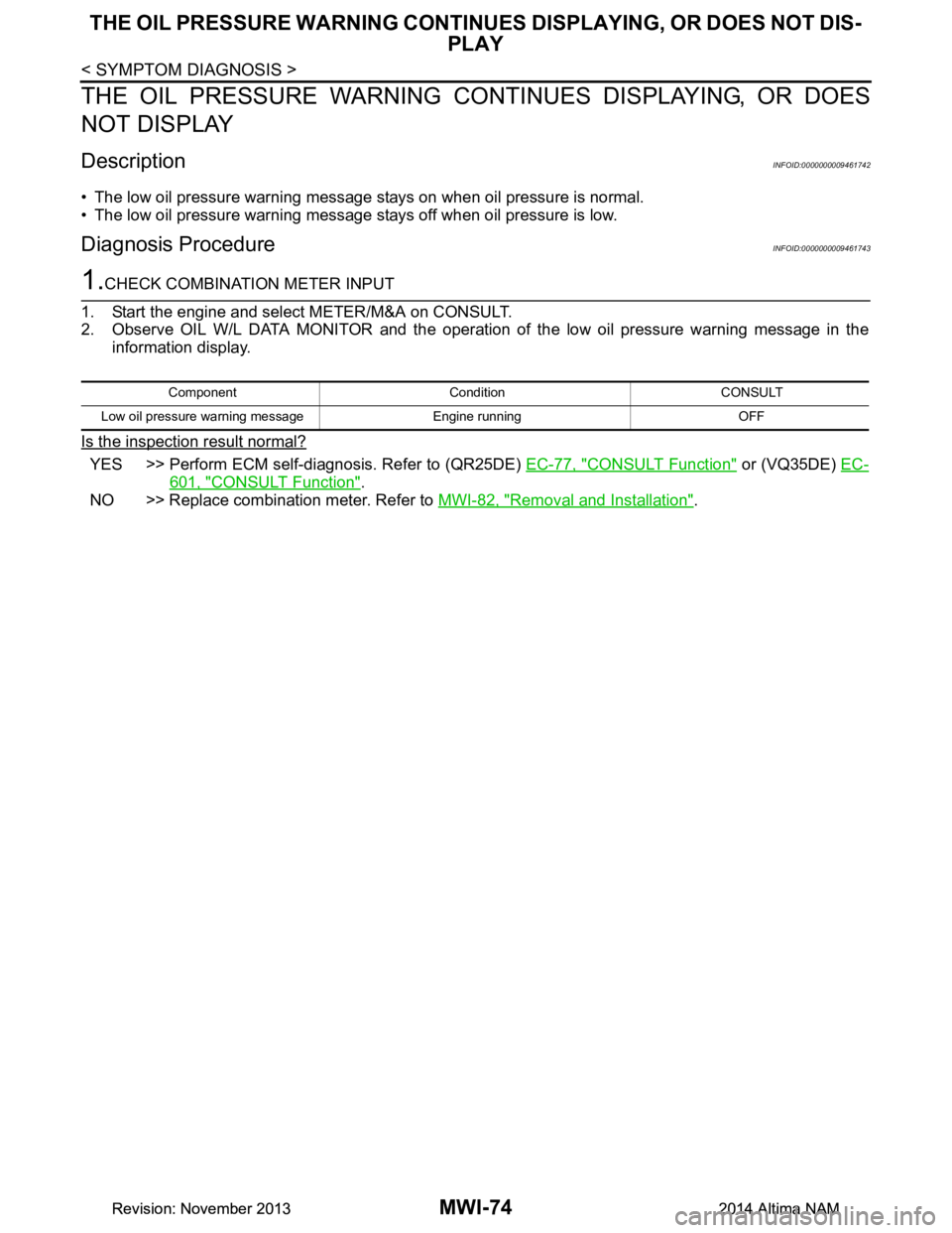
• The low oil pressure warning message stays on when oil pressure is normal.
• The low oil pressure warning message stays off when oil pressure is low.
Diagnosis ProcedureINFOID:0000000009461743
1.CHECK COMBINATION METER INPUT
1. Start the engine and select METER/M&A on CONSULT.
2. Observe OIL W/L DATA MONITOR and the operation of the low oil pressure warning message in the
information display.
Is the inspection result normal?
YES >> Perform ECM self-diagnosis. Refer to (QR25DE) EC-77, "CONSULT Function" or (VQ35DE) EC-
601, "CONSULT Function".
NO >> Replace combination meter. Refer to MWI-82, "Removal and Installation"
.
Component Condi tion CONSULT
Low oil pressure warning message Engine running OFF
Revision: November 20132014 Altima NAMRevision: November 20132014 Altima NAM
Page 3378 of 4801
![NISSAN TEANA 2014 Service Manual
PCS
B2098 IGNITION RELAY ON STUCKPCS-29
< DTC/CIRCUIT DIAGNOSIS > [IPDM E/R]
C
D E
F
G H
I
J
K L
B
A
O P
N
B2098 IGNITION RELAY ON STUCK
DTC LogicINFOID:0000000009941319
DTC DETECTION LOGIC
DTC CO NISSAN TEANA 2014 Service Manual
PCS
B2098 IGNITION RELAY ON STUCKPCS-29
< DTC/CIRCUIT DIAGNOSIS > [IPDM E/R]
C
D E
F
G H
I
J
K L
B
A
O P
N
B2098 IGNITION RELAY ON STUCK
DTC LogicINFOID:0000000009941319
DTC DETECTION LOGIC
DTC CO](/manual-img/5/57390/w960_57390-3377.png)
PCS
B2098 IGNITION RELAY ON STUCKPCS-29
< DTC/CIRCUIT DIAGNOSIS > [IPDM E/R]
C
D E
F
G H
I
J
K L
B
A
O P
N
B2098 IGNITION RELAY ON STUCK
DTC LogicINFOID:0000000009941319
DTC DETECTION LOGIC
DTC CONFIRMATION PROCEDURE
1.PERFORM DTC CONFIRMATION PROCEDURE
1. Turn the power supply position to start under the following conditions and wait for at least 1 second.
- CVT selector lever is in the P (Park) or N (Neutral) position.
- Depress the brake pedal
2. Check “Self-diagnostic result” with CONSULT.
Is DTC detected?
YES >> Refer to PCS-29, "Diagnosis Procedure".
NO >> Inspection End.
Diagnosis ProcedureINFOID:0000000009941320
1. PERFORM SELF DIAGNOSTIC RESULT
Perform Self Diagnostic Result of IPDM E/R using CONSULT.
Is display history of DTC B2098 CRNT?
YES >> Replace IPDM E/R. Refer to PCS-32, "Removal and Installation".
NO >> Refer to GI-43, "Intermittent Incident"
.
CONSULT Display DTC Detectio n Condition Possible Cause
IGN RELAY ON
[B2098] The ignition relay ON is detected for 1 second at ignition
switch OFF
(CPU monitors the status at the contact and excitation
coil circuits of the ignition relay inside it) IPDM E/R
Revision: November 20132014 Altima NAMRevision: November 20132014 Altima NAM