2014 NISSAN TEANA check oil
[x] Cancel search: check oilPage 3980 of 4801
SR-18
< REMOVAL AND INSTALLATION >
FRONT PASSENGER AIR BAG MODULE
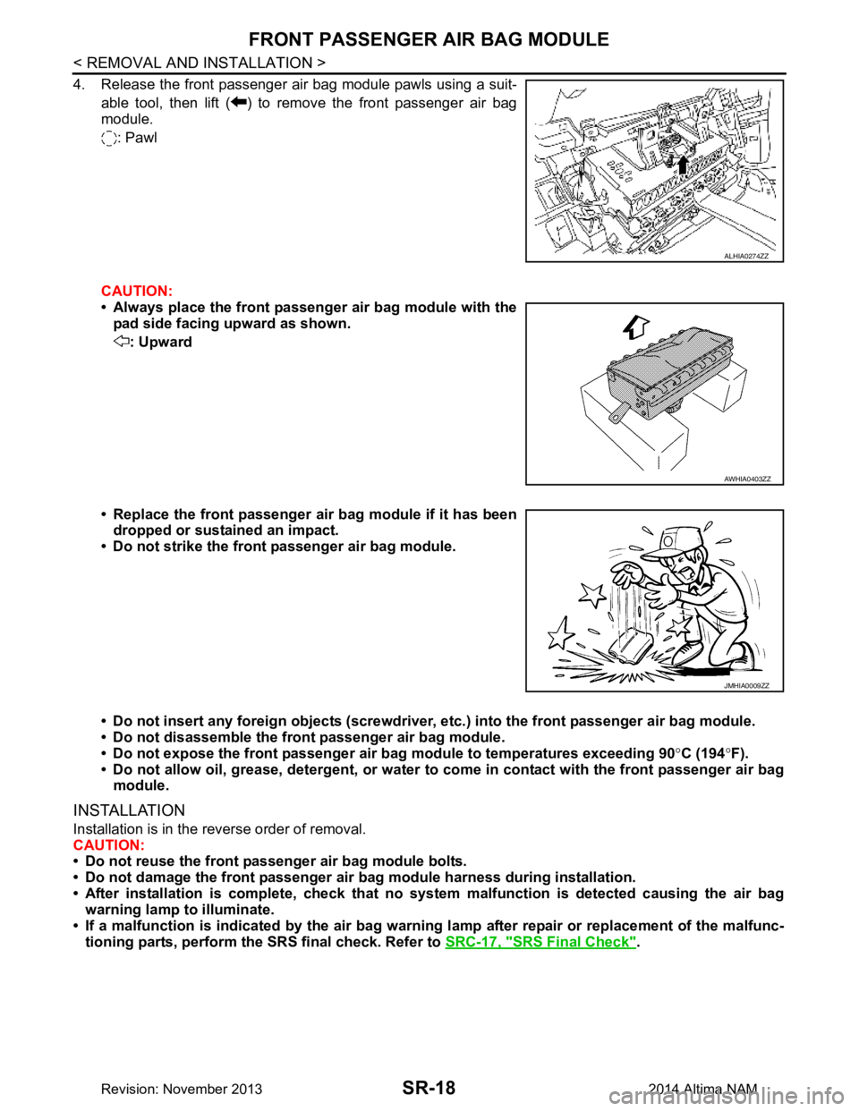
4. Release the front passenger air bag module pawls using a suit-able tool, then lift ( ) to remove the front passenger air bag
module.
: Pawl
CAUTION:
• Always place the front passenger air bag module with the pad side facing upward as shown.
: Upward
• Replace the front passenger air bag module if it has been dropped or sustained an impact.
• Do not strike the front passenger air bag module.
• Do not insert any foreign objects (screwdriver , etc.) into the front passenger air bag module.
• Do not disassemble the front passenger air bag module.
• Do not expose the front passenger air bag module to temperatures exceeding 90 °C (194 °F).
• Do not allow oil, grease, detergent, or water to come in contact with the front passenger air bag
module.
INSTALLATION
Installation is in the reverse order of removal.
CAUTION:
• Do not reuse the front passenger air bag module bolts.
• Do not damage the front passenger air bag module harness during installation.
• After installation is complete, check that no syst em malfunction is detected causing the air bag
warning lamp to illuminate.
• If a malfunction is indicated by the air bag warnin g lamp after repair or replacement of the malfunc-
tioning parts, perform the SRS final check. Refer to SRC-17, "SRS Final Check"
.
ALHIA0274ZZ
AWHIA0403ZZ
JMHIA0009ZZ
Revision: November 20132014 Altima NAM
Page 3982 of 4801
SR-20
< REMOVAL AND INSTALLATION >
SIDE CURTAIN AIR BAG MODULE
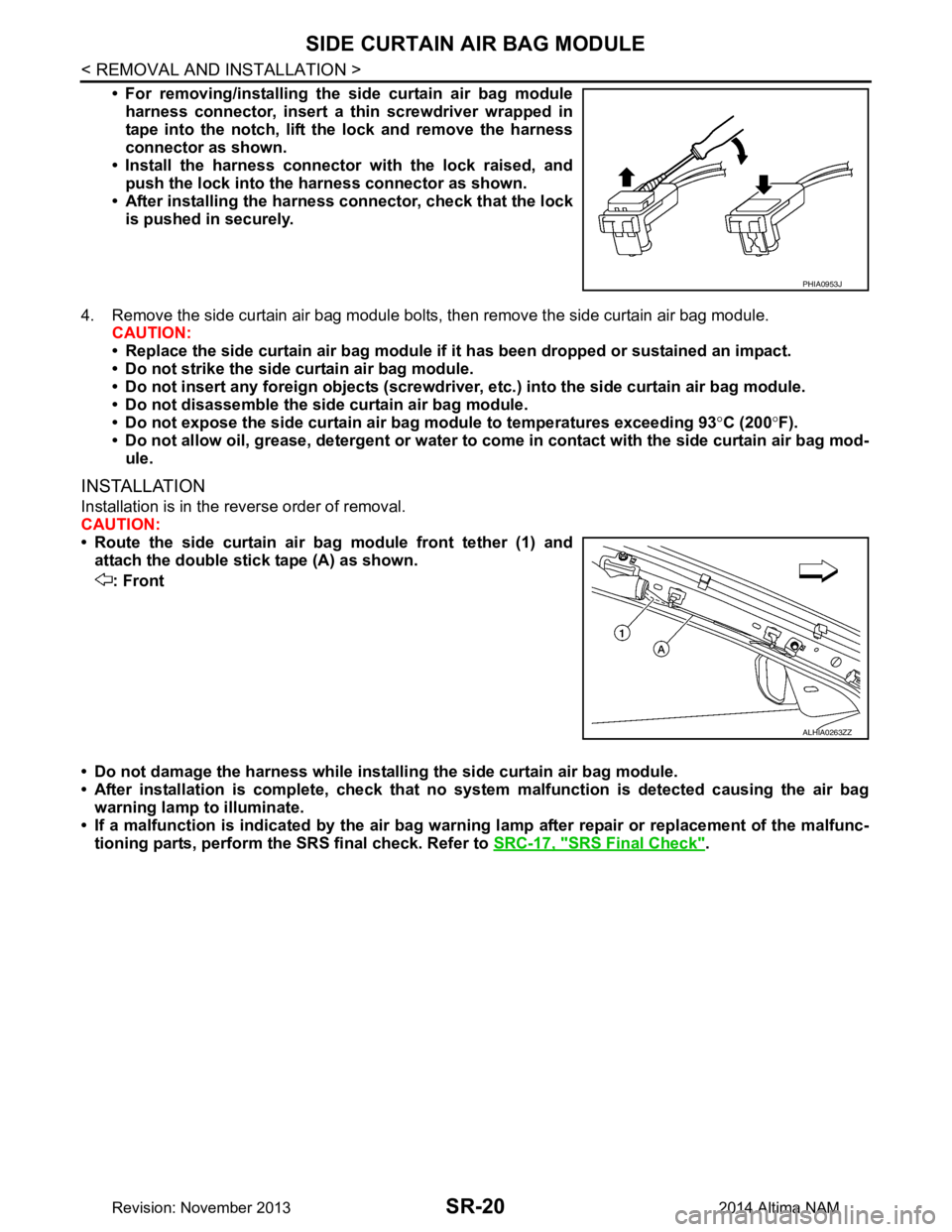
• For removing/installing the side curtain air bag moduleharness connector, insert a thin screwdriver wrapped in
tape into the notch, lift the lock and remove the harness
connector as shown.
• Install the harness connector with the lock raised, and push the lock into the harness connector as shown.
• After installing the harness connector, check that the lock
is pushed in securely.
4. Remove the side curtain air bag module bolts, then remove the side curtain air bag module. CAUTION:
• Replace the side curtain air bag module if it has been dropped or sustained an impact.
• Do not strike the side curtain air bag module.
• Do not insert any foreign objects (screwdriver , etc.) into the side curtain air bag module.
• Do not disassemble the side curtain air bag module.
• Do not expose the side curtain air bag module to temperatures exceeding 93 °C (200 °F).
• Do not allow oil, grease, detergent or water to co me in contact with the side curtain air bag mod-
ule.
INSTALLATION
Installation is in the reverse order of removal.
CAUTION:
• Route the side curtain air bag module front tether (1) and attach the double stick tape (A) as shown.
: Front
• Do not damage the harness while installi ng the side curtain air bag module.
• After installation is complete, check that no syst em malfunction is detected causing the air bag
warning lamp to illuminate.
• If a malfunction is indicated by the air bag warnin g lamp after repair or replacement of the malfunc-
tioning parts, perform the SRS final check. Refer to SRC-17, "SRS Final Check"
.
PHIA0953J
ALHIA0263ZZ
Revision: November 20132014 Altima NAM
Page 4104 of 4801

ST-1
STEERING
C
D E
F
H I
J
K L
M
SECTION ST
A
B
ST
N
O P
CONTENTS
STEERING SYSTEM
PRECAUTION ................ ...............................3
PRECAUTIONS .............................................. .....3
Precaution for Supplemental Restraint System
(SRS) "AIR BAG" and "SEAT BELT PRE-TEN-
SIONER" ............................................................. ......
3
Precaution for Steering System .......................... ......3
Precaution for Work ............................................ ......3
PREPARATION ............................................5
PREPARATION .............................................. .....5
Special Service Tool ........................................... ......5
Commercial Service Tool ..........................................5
SYSTEM DESCRIPTION ..............................7
COMPONENT PARTS ................................... .....7
HEATED STEERING WHEEL SYSTEM ............... ......7
HEATED STEERING WHEEL SYSTEM : Compo-
nent Parts Location ............................................. ......
7
HEATED STEERING WHEEL SYSTEM : Compo-
nent Description .................................................. ......
7
SYSTEM ..............................................................8
HEATED STEERING WHEEL SYSTEM ............... ......8
HEATED STEERING WHEEL SYSTEM : System
Diagram ............................................................... ......
8
HEATED STEERING WHEEL SYSTEM : System
Description .......................................................... ......
8
ECU DIAGNOSIS INFORMATION ...............9
A/C AUTO AMP. ............................................. .....9
List of ECU Reference ........................................ ......9
WIRING DIAGRAM ......................................10
HEATED STEERING WHEEL ........................ ....10
Wiring Diagram ................................................... ....10
BASIC INSPECTION ...................................13
DIAGNOSIS AND REPAIR WORK FLOW .......13
Work Flow ............................................................ ....13
POWER STEERING FLUID ..............................15
Inspection ................................................................15
STEERING WHEEL ..........................................16
Inspection ................................................................16
STEERING COLUMN ........................................18
Inspection ................................................................18
POWER STEERING OIL PUMP .......................19
Inspection ................................................................19
STEERING GEAR AND LINKAGE ...................20
Inspection ................................................................20
DTC/CIRCUIT DIAGNOSIS .........................21
POWER SUPPLY AND GROUND CIRCUIT ....21
A/C AUTO AMP. .................................................... ....21
A/C AUTO AMP. : Diagnosis Procedure .................21
HEATED STEERING WHEEL SYSTEM ...........22
Component Function Check ....................................22
Diagnosis Procedure ...............................................22
Component Inspection (Heated Steering Wheel
Switch) ................................................................. ....
24
Component Inspection (Heated Steering Relay) .....24
Component Inspection (Heated Steering Wheel) ....25
HEATED STEERING WHEEL SWITCH INDI-
CATOR LAMP ...................................................
26
Component Function Check ................................ ....26
Diagnosis Procedure ...............................................26
SYMPTOM DIAGNOSIS ..............................28
STEERING COLUMN ........................................28
Revision: November 20132014 Altima NAMRevision: November 20132014 Altima NAM
Page 4106 of 4801
PRECAUTIONSST-3
< PRECAUTION >
C
D E
F
H I
J
K L
M A
B
ST
N
O P
PRECAUTION
PRECAUTIONS
Precaution for Supplemental Restraint System (SRS) "AIR BAG" and "SEAT BELT
PRE-TENSIONER"
INFOID:0000000009951723
The Supplemental Restraint System such as “A IR BAG” and “SEAT BELT PRE-TENSIONER”, used along
with a front seat belt, helps to reduce the risk or severi ty of injury to the driver and front passenger for certain
types of collision. Information necessary to service t he system safely is included in the SR and SB section of
this Service Manual.
WARNING:
• To avoid rendering the SRS inoper ative, which could increase the risk of personal injury or death in
the event of a collision which would result in air bag inflation, all maintenance must be performed by
an authorized NISSAN/INFINITI dealer.
• Improper maintenance, including in correct removal and installation of the SRS, can lead to personal
injury caused by unintentional act ivation of the system. For removal of Spiral Cable and Air Bag
Module, see the SR section.
• Do not use electrical test equipm ent on any circuit related to the SRS unless instructed to in this
Service Manual. SRS wiring harnesses can be identi fied by yellow and/or orange harnesses or har-
ness connectors.
PRECAUTIONS WHEN USING POWER TOOLS (AIR OR ELECTRIC) AND HAMMERS
WARNING:
• When working near the Airbag Diagnosis Sensor Un it or other Airbag System sensors with the Igni-
tion ON or engine running, DO NOT use air or el ectric power tools or strike near the sensor(s) with a
hammer. Heavy vibration could activate the sensor( s) and deploy the air bag(s), possibly causing
serious injury.
• When using air or electric power tools or hammers , always switch the Ignition OFF, disconnect the
battery and wait at least three mi nutes before performing any service.
Precaution for Steering SystemINFOID:0000000009461240
• Before disassembly, thoroughly clean the outside of the unit.
• Disassembly should be done in a clean work area. It is im portant to prevent the internal parts from becoming
contaminated by dirt or other foreign matter.
• For easier and proper assembly, place disassembled parts in order on a parts rack.
• Use nylon cloth or paper towels to clean the parts; common shop rags can leave lint that might interfere with
their operation.
• Before inspection or reassembly, carefully clean al l parts with a general purpose, non-flammable solvent.
• Before assembly, apply a coat of recommended Genuine NISSAN PSF or equivalent to hydraulic parts.
Petroleum jelly may be applied to O-rings and seals. Do not use any grease.
• Replace all gaskets, seals and O-rings. Avoid damaging O-rings, seals and gaskets during installation. Per- form functional tests whenever designated.
Precaution for WorkINFOID:0000000009461241
• When removing or disassembling each component, be ca reful not to damage or deform it. If a component
may be subject to interference, be sure to protect it with a shop cloth.
• When removing (disengaging) components with a screwdriver or similar tool, be sure to wrap the component
with a shop cloth or vinyl tape to protect it.
• Protect the removed parts with a shop cloth and prevent them from being dropped.
• Replace a deformed or damaged clip.
• If a part is specified as a non-reusabl e part, always replace it with a new one.
• Be sure to tighten bolts and nuts securely to the specified torque.
• After installation is complete, be sure to check that each part works properly.
• Follow the steps below to clean components:
- Water soluble dirt:
• Dip a soft cloth into lukewarm water, wring the water out of the cloth and wipe the dirty area.
• Then rub with a soft, dry cloth.
-Oily dirt:
Revision: November 20132014 Altima NAMRevision: November 20132014 Altima NAM
Page 4118 of 4801
POWER STEERING FLUIDST-15
< BASIC INSPECTION >
C
D E
F
H I
J
K L
M A
B
ST
N
O P
POWER STEERING FLUID
InspectionINFOID:0000000009461251
FLUID LEVEL
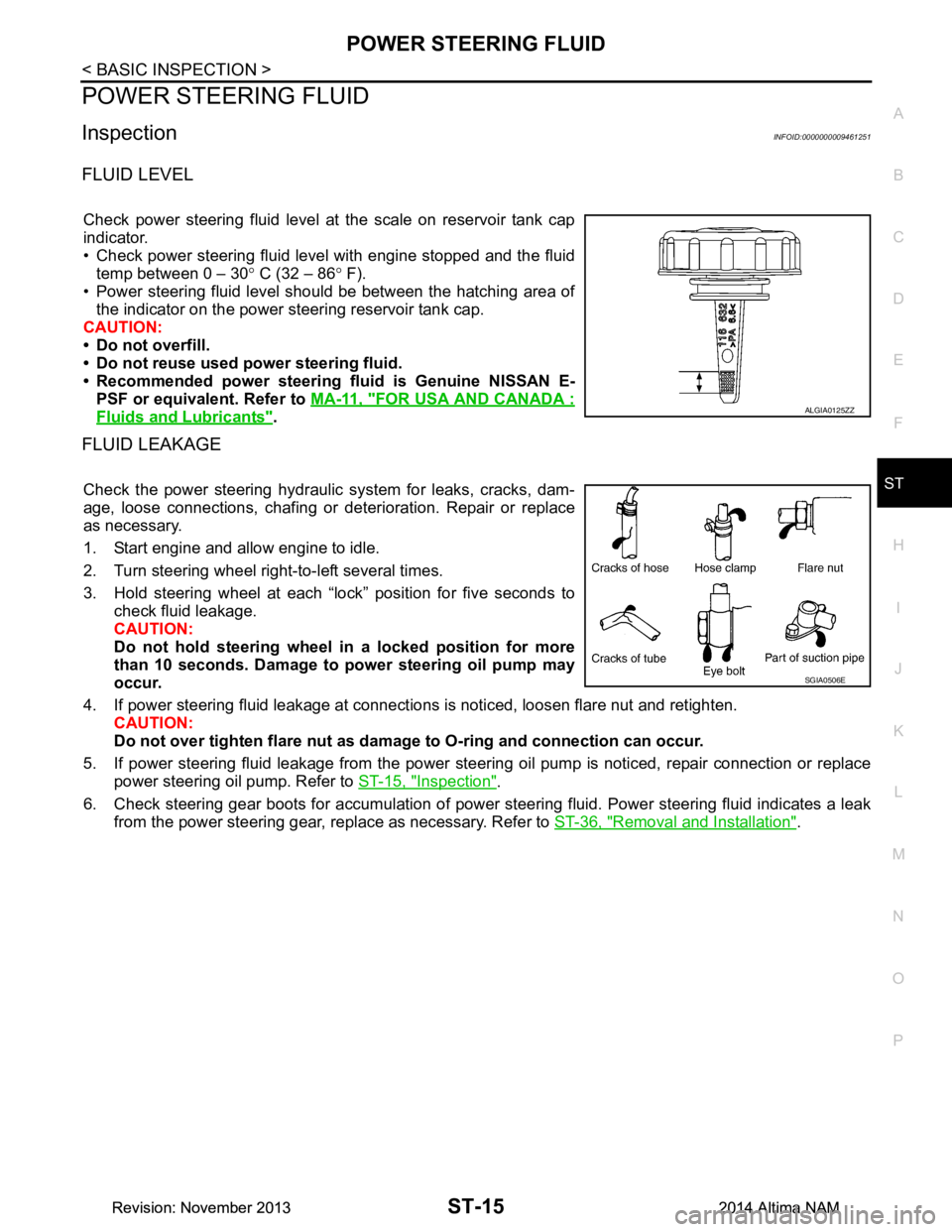
Check power steering fluid level at the scale on reservoir tank cap
indicator.
• Check power steering fluid level with engine stopped and the fluid temp between 0 – 30 ° C (32 – 86 ° F).
• Power steering fluid level should be between the hatching area of the indicator on the power steering reservoir tank cap.
CAUTION:
• Do not overfill.
• Do not reuse used power steering fluid.
• Recommended power steering fluid is Genuine NISSAN E-
PSF or equivalent. Refer to MA-11, "FOR USA AND CANADA :
Fluids and Lubricants".
FLUID LEAKAGE
Check the power steering hydraulic system for leaks, cracks, dam-
age, loose connections, chafing or det erioration. Repair or replace
as necessary.
1. Start engine and allow engine to idle.
2. Turn steering wheel right-to-left several times.
3. Hold steering wheel at each “lock” position for five seconds to check fluid leakage.
CAUTION:
Do not hold steering wheel in a locked position for more
than 10 seconds. Damage to power steering oil pump may
occur.
4. If power steering fluid leakage at connections is noticed, loosen flare nut and retighten.
CAUTION:
Do not over tighten flare nut as damage to O-ring and connection can occur.
5. If power steering fluid leakage from the power steer ing oil pump is noticed, repair connection or replace
power steering oil pump. Refer to ST-15, "Inspection"
.
6. Check steering gear boots for accumulation of power st eering fluid. Power steering fluid indicates a leak
from the power steering gear, replace as necessary. Refer to ST-36, "Removal and Installation"
.
ALGIA0125ZZ
SGIA0506E
Revision: November 20132014 Altima NAMRevision: November 20132014 Altima NAM
Page 4133 of 4801
ST-30
< PERIODIC MAINTENANCE >
POWER STEERING FLUID
PERIODIC MAINTENANCE
POWER STEERING FLUID
Draining and RefillingINFOID:0000000009461266
DRAINING
1. Disconnect the high and low pressure piping from power steering gear.
2. Drain power steering fluid into a suitable container.
REFILLING
1. Fill power steering reservoir while checking power steering fluid level.
2. Bleed air from power steering hydraulic system. Refer to ST-30, "Air Bleeding Hydraulic System"
.
3. Check for power steering fluid leaks.
Air Bleeding Hydraulic SystemINFOID:0000000009461267
AIR BLEEDING HYDRAULIC SYSTEM
If air bleeding is not complete, excessive noise in the power steering oil pump will be present.
1. Make sure engine is off.
2. Turn the steering wheel from the full right stop pos ition and then to full left stop position several times.
Repeat until bubbles are no longer being generated in the reservoir.
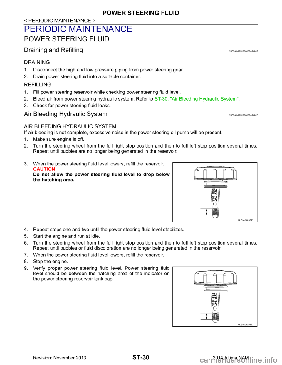
3. When the power steering fluid level lowers, refill the reservoir. CAUTION:
Do not allow the power steerin g fluid level to drop below
the hatching area.
4. Repeat steps one and two until the power steering fluid level stabilizes.
5. Start the engine and run at idle.
6. Turn the steering wheel from the full right stop pos ition and then to full left stop position several times.
Repeat until bubbles or fluid discoloration are no longer being generated in the reservoir.
7. When the power steering fluid level lowers, refill the reservoir.
8. Stop the engine.
9. Verify proper power steering fluid level. Power steering fluid level should be between the hatching area of the indicator on
the power steering reservoir tank cap.
ALGIA0125ZZ
ALGIA0125ZZ
Revision: November 20132014 Altima NAMRevision: November 20132014 Altima NAM
Page 4173 of 4801
STC-22
< DTC/CIRCUIT DIAGNOSIS >
C1143 STEERING ANGLE SENSOR
DTC/CIRCUIT DIAGNOSIS
C1143 STEERING ANGLE SENSOR
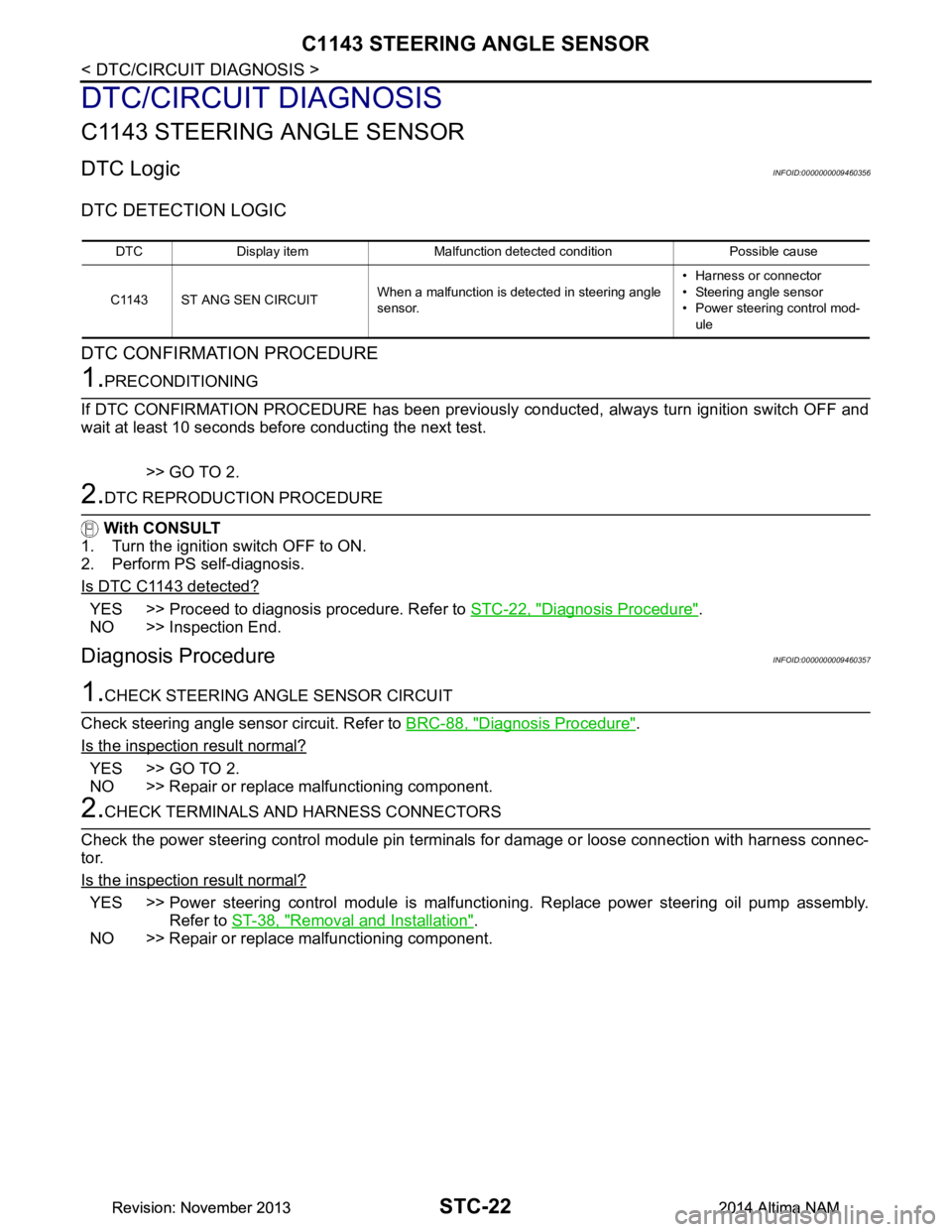
DTC LogicINFOID:0000000009460356
DTC DETECTION LOGIC
DTC CONFIRMATION PROCEDURE
1.PRECONDITIONING
If DTC CONFIRMATION PROCEDURE has been previously conducted, always turn ignition switch OFF and
wait at least 10 seconds before conducting the next test.
>> GO TO 2.
2.DTC REPRODUCTION PROCEDURE
With CONSULT
1. Turn the ignition switch OFF to ON.
2. Perform PS self-diagnosis.
Is DTC C1143 detected?
YES >> Proceed to diagnosis procedure. Refer to STC-22, "Diagnosis Procedure".
NO >> Inspection End.
Diagnosis ProcedureINFOID:0000000009460357
1.CHECK STEERING ANGLE SENSOR CIRCUIT
Check steering angle sensor circuit. Refer to BRC-88, "Diagnosis Procedure"
.
Is the inspection result normal?
YES >> GO TO 2.
NO >> Repair or replace malfunctioning component.
2.CHECK TERMINALS AND HARNESS CONNECTORS
Check the power steering control module pin termi nals for damage or loose connection with harness connec-
tor.
Is the inspection result normal?
YES >> Power steering control module is malfunctioni ng. Replace power steering oil pump assembly.
Refer to ST-38, "Removal and Installation"
.
NO >> Repair or replace malfunctioning component.
DTC Display item Malfunction detected condition Possible cause
C1143 ST ANG SEN CIRCUIT When a malfunction is detected in steering angle
sensor. • Harness or connector
• Steering angle sensor
• Power steering control mod-
ule
Revision: November 20132014 Altima NAMRevision: November 20132014 Altima NAM
Page 4176 of 4801
C1601 BATTERY POWER SUPPLYSTC-25
< DTC/CIRCUIT DIAGNOSIS >
C
D E
F
H I
J
K L
M A
B
STC
N
O P
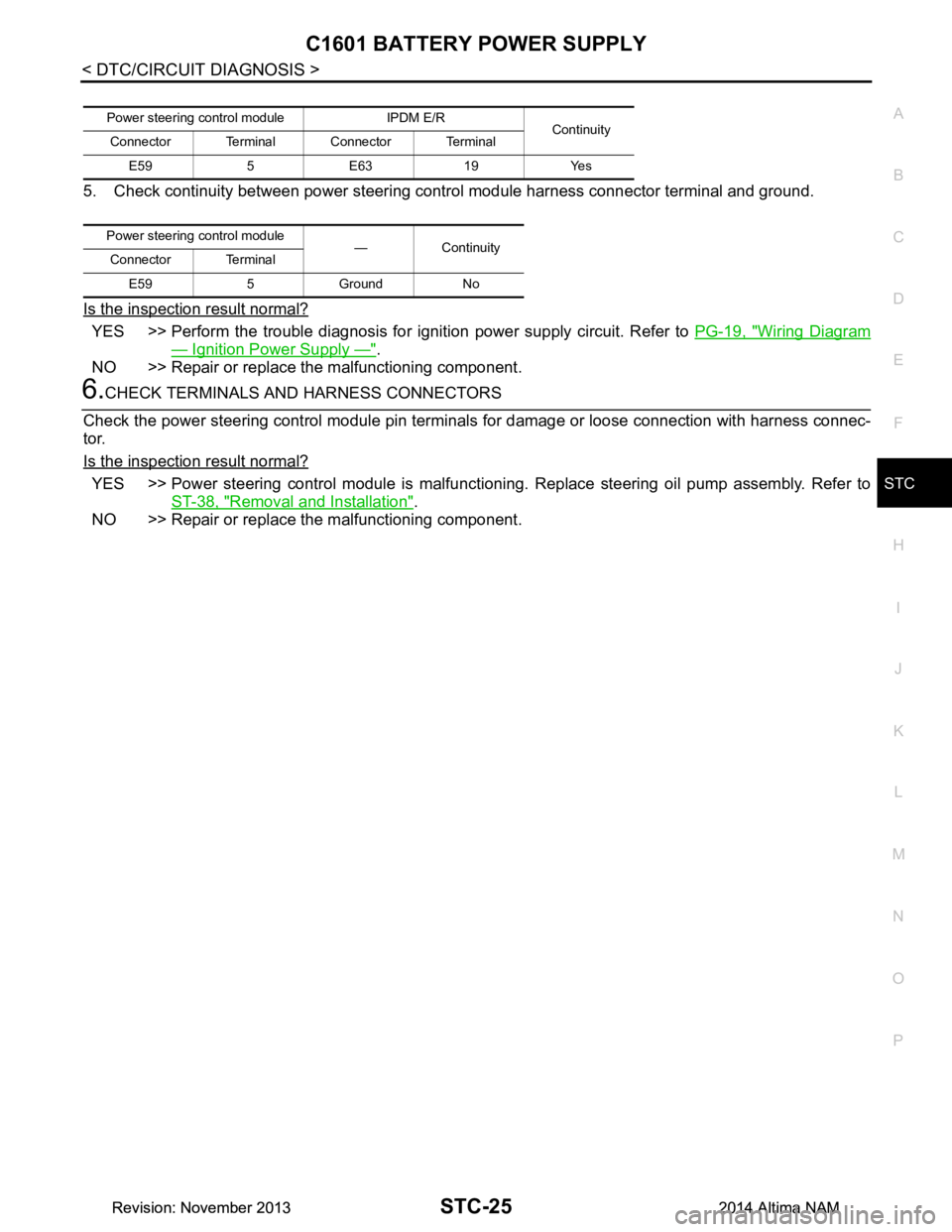
5. Check continuity between power steering control module harness connector terminal and ground.
Is the inspection result normal?
YES >> Perform the trouble diagnosis for i gnition power supply circuit. Refer to PG-19, "Wiring Diagram
— Ignition Power Supply —".
NO >> Repair or replace the malfunctioning component.
6.CHECK TERMINALS AND HARNESS CONNECTORS
Check the power steering control module pin terminal s for damage or loose connection with harness connec-
tor.
Is the inspection result normal?
YES >> Power steering control module is malfunctioni ng. Replace steering oil pump assembly. Refer to
ST-38, "Removal and Installation"
.
NO >> Repair or replace the malfunctioning component.
Power steering cont rol module IPDM E/R
Continuity
Connector Terminal Connector Terminal
E59 5 E63 19 Yes
Power steering control module
—Continuity
Connector Terminal
E59 5 Ground No
Revision: November 20132014 Altima NAMRevision: November 20132014 Altima NAM