2014 NISSAN TEANA Pro pressure
[x] Cancel search: Pro pressurePage 2200 of 4801
![NISSAN TEANA 2014 Service Manual
EM-202
< REMOVAL AND INSTALLATION >[VQ35DE]
CAMSHAFT
• Using inside micrometer, measure diameter of valve lifter bore of
cylinder head. Refer to EM-247, "Camshaft"
EM-247, "Camshaft".
• If out of NISSAN TEANA 2014 Service Manual
EM-202
< REMOVAL AND INSTALLATION >[VQ35DE]
CAMSHAFT
• Using inside micrometer, measure diameter of valve lifter bore of
cylinder head. Refer to EM-247, "Camshaft"
EM-247, "Camshaft".
• If out of](/manual-img/5/57390/w960_57390-2199.png)
EM-202
< REMOVAL AND INSTALLATION >[VQ35DE]
CAMSHAFT
• Using inside micrometer, measure diameter of valve lifter bore of
cylinder head. Refer to EM-247, "Camshaft"
EM-247, "Camshaft".
• If out of the specified range, replace the cylinder head assembly.
Calculation of Valve Lifter Clearance
• (Valve lifter clearance) = (hole diameter for valve li fter) – (outer diameter of valve lifter) Refer to EM-247,
"Camshaft".
• If out of specified range, replace either or both valve lifter and cylinder head assembly.
Inspection after InstallationINFOID:0000000009460570
INSPECTION OF CAMSHAFT SPROCKET (INT) OIL GROOVE
WARNING:
• Check when engine is cold so as to pr event burns from any splashing engine oil.
CAUTION:
• Perform this inspection only when DTC P0011 is detected in self-diagnostic results of CONSULT and
it is directed according to inspection procedure of EC section. Refer to EC-716, "Diagnosis Proce-
dure".
1. Check engine oil level. Refer to MA-26, "ENGINE OIL : Inspection"
.
2. Perform the following procedure so as to prevent the engine from being unintentionally started while
checking.
a. Release fuel pressure. Refer to FL-5, "Inspection"
.
b. Disconnect ignition coil and injector harness connectors if practical.
3. Remove intake valve timing control solenoid valve.
4. Crank engine, and then make sure that engine oil comes out from intake valve timing control solenoid valve cover oil hole.
End cranking after checking.
WARNING:
Be careful not to touch rotating parts (drive belts, idler pul-
ley, and crankshaft pulley, etc.).
CAUTION:
• Engine oil may squirt from intake valve timing control solenoid valve installation hole during cranking. Use a
shop cloth to prevent engi ne oil from splashing on
worker, engine components and vehicle.
• Do not allow engine oil to get on rubber components such
as drive belts or engine mount insulators. I mmediately wipe off any splashed engine oil.
5. Clean oil groove between oil strainer and intake valve timing control solenoid valve if engine oil does not come out from intake valve timing control solenoid valve cover oil hole.
6. Remove components between intake valve timing c ontrol solenoid valve and camshaft sprocket (INT),
and then check each oil groove for clogging.
• Clean oil groove if necessary.
7. After inspection, installation of the remaining components is in the reverse order of removal.
SEM867E
KBIA2686E
Revision: November 20132014 Altima NAM
Page 2212 of 4801
![NISSAN TEANA 2014 Service Manual
EM-214
< REMOVAL AND INSTALLATION >[VQ35DE]
CYLINDER HEAD
1. To remove valve guide, heat cylinder head to 110
° to 130 °C
(230 ° to 266 °F) by soaking in heated oil.
WARNING:
Cylinder head conta NISSAN TEANA 2014 Service Manual
EM-214
< REMOVAL AND INSTALLATION >[VQ35DE]
CYLINDER HEAD
1. To remove valve guide, heat cylinder head to 110
° to 130 °C
(230 ° to 266 °F) by soaking in heated oil.
WARNING:
Cylinder head conta](/manual-img/5/57390/w960_57390-2211.png)
EM-214
< REMOVAL AND INSTALLATION >[VQ35DE]
CYLINDER HEAD
1. To remove valve guide, heat cylinder head to 110
° to 130 °C
(230 ° to 266 °F) by soaking in heated oil.
WARNING:
Cylinder head contains heat. When working, wear protective
equipment to avoid getting burned.
2. Drive out the valve guide with a press [under a 20 kN (2.2 US ton) pressure] or hammer and suitable tool.
3. Ream cylinder head valve guide hole.
4. Heat cylinder head to 110 ° to 130 °C (230 ° to 266 °F) by soaking
in heated oil and press new valve guide from camshaft side into
the cylinder head to the dimensions as shown.
WARNING:
Cylinder head contains heat . When working, wear protec-
tive equipment to avo id getting burned.
SEM008A
SEM931C
Valve guide hole diameter
(for service parts), intake
and exhaust : 10.175 - 10.196 mm
(0.4006 - 0.4014 in)
SEM932C
Projection (L) : 12.6 - 12.8 mm (0.496 - 0.504 in)
SEM950E
Revision: November 20132014 Altima NAM
Page 2219 of 4801
![NISSAN TEANA 2014 Service Manual
ENGINE ASSEMBLYEM-221
< UNIT REMOVAL AND INSTALLATION > [VQ35DE]
C
D E
F
G H
I
J
K L
M A
EM
NP
O
• Do not damage the edge of the crankshaft
position sensor (POS) or the ring gear teeth.
REMOVAL
NISSAN TEANA 2014 Service Manual
ENGINE ASSEMBLYEM-221
< UNIT REMOVAL AND INSTALLATION > [VQ35DE]
C
D E
F
G H
I
J
K L
M A
EM
NP
O
• Do not damage the edge of the crankshaft
position sensor (POS) or the ring gear teeth.
REMOVAL](/manual-img/5/57390/w960_57390-2218.png)
ENGINE ASSEMBLYEM-221
< UNIT REMOVAL AND INSTALLATION > [VQ35DE]
C
D E
F
G H
I
J
K L
M A
EM
NP
O
• Do not damage the edge of the crankshaft
position sensor (POS) or the ring gear teeth.
REMOVAL
NOTE:
When removing components such as hoses, tubes/lines, etc. , cap or plug openings to prevent fluid from spill-
ing.
1. Remove hood assembly. Refer to DLK-170, "HOOD ASSEMBLY : Removal and Installation"
.
2. Release fuel pressure. Refer to FL-5, "Inspection"
.
3. Drain engine coolant. Refer to CO-36, "Changing Engine Coolant"
.
4. Drain power steering fluid. Refer to ST-30, "Draining and Refilling"
.
5. Remove front wheels and tires (RH/LH). Refer to WT-55, "Adjustment"
.
6. Remove fender protector side covers (RH/LH). Refer to EXT-26, "FENDER PROTECTOR : Removal and
Installation".
7. Remove the engine under cover. Refer to EXT-17, "Removal and Installation"
.
8. Remove the engine room cover. Refer to EM-143, "Removal and Installation"
.
9. Remove air duct hose and resonator assembly and air cleaner case assembly with mass air flow sensor.
Refer to EM-144, "Removal and Installation"
.
10. Remove battery and battery tray. Refer to PG-74, "Removal and Installation (Battery Tray)"
.
11. Remove transmission control module. Refer to TM-183, "Removal and Installation"
.
12. Remove cowl top. Refer to EXT-24, "Removal and Installation"
.
13. Remove strut brace using power tools. Refer to FSU-19, "Exploded View"
.
14. Remove IPDM E/R. Refer to PCS-32, "Removal and Installation"
.
15. Remove the following parts: • EVAP vacuum hose
• Brake booster vacuum hose
• Heater hoses (engine side)
16. Disconnect transaxle shift control cables. Refer to TM-380, "Removal and Installation"
.
17. Remove upper and lower radiator hoses.
18. Disconnect CVT fluid cooler hoses.
19. Remove power steering reservoir, suction hose and high pressure hose.
20. Disconnect fuel hose quick connection at vehicle piping side. Refer to EM-163, "Removal and Installa-
tion".
21. Remove the front exhaust tube using power tools. Refer to EX-10, "Exploded View"
.
22. Discharge and recover the R134a refrigerant. Refer to HA-23, "Recycle Refrigerant"
.
23. Remove the A/C compressor using power tools. Refer to HA-30, "COMPRESSOR : Removal and Installa-
tion".
24. Install engine slingers into front of LH cylinder head and rear of RH cylinder head.
• (A): RH cylinder head
ALBIA0262GB
Revision: November 20132014 Altima NAM
Page 2220 of 4801
![NISSAN TEANA 2014 Service Manual
EM-222
< UNIT REMOVAL AND INSTALLATION >[VQ35DE]
ENGINE ASSEMBLY
• (B): LH cylinder head
25. Remove rear cover plate.
26. Remove the torque converter nuts.
27. Remove nuts of stabilizer connectin NISSAN TEANA 2014 Service Manual
EM-222
< UNIT REMOVAL AND INSTALLATION >[VQ35DE]
ENGINE ASSEMBLY
• (B): LH cylinder head
25. Remove rear cover plate.
26. Remove the torque converter nuts.
27. Remove nuts of stabilizer connectin](/manual-img/5/57390/w960_57390-2219.png)
EM-222
< UNIT REMOVAL AND INSTALLATION >[VQ35DE]
ENGINE ASSEMBLY
• (B): LH cylinder head
25. Remove rear cover plate.
26. Remove the torque converter nuts.
27. Remove nuts of stabilizer connecting rods from struts. Refer to FSU-19, "Exploded View"
.
28. Remove front wheel speed sensors and position aside. Refer to BRC-124, "Removal and Installation -
Front Wheel Sensor".
29. Remove front brake rotors. Refer to BR-36, "BRAKE CALIPER ASSEMBLY : Removal and Installation"
.
30. Remove piston rod nut. Refer to FSU-19, "Exploded View"
.
31. Remove front drive shaft (LH/RH). Refer to FAX-10, "Removal and Installation (LH)"
and FAX-12,
"Removal and Installation (RH)".
32. Remove RH drive shaft center bearing bracket.
33. Remove lower steering column pinch bolt. Refer to ST-33, "Exploded View"
.
34. Remove three way catalyst (manifold) (bank 1) heat shield.
35. Disconnect front and rear engine mounting insulator vacuum hoses.
36. Remove front and rear engine mounting insulator nut.
37. Position a suitable support table under suspension member and engine assembly. TM-206, "Removal and
Installation"
38. Disconnect the engine mounting insulator (LH), upper torque rod, and engine mounting insulator (RH).
39. For additional safety, secure the engine in position with suitable tool.
40. Remove suspension member bolts. Refer to FSU-19, "Exploded View"
.
41. Carefully lower the engine, transaxle assembly and suspension member using Tool, avoiding interference
with the vehicle body.
CAUTION:
• Before and during this procedure, alw ays check if any harnesses are left connected.
• Avoid any damage to, or any oil/grease smearin g or spilling onto the engine mounting insula-
tors.
42. Remove the starter motor. Refer to STR-23, "VQ35DE : Removal and Installation"
.
43. Remove the crankshaft position sensor (POS).
44. Remove engine and transaxle harness.
45. Separate the engine and transaxle and mount the engine on a suitable engine stand.
INSTALLATION
Installation is in the reverse order of removal.
NOTE:
Tighten transmission bolts to specification. Refer to TM-206, "Removal and Installation"
.
INSPECTION AFTER INSTALLATION
• Before starting engine, check oil/fluid levels including engine coolant and engine oil. If less than required
quantity, fill to the specified level. Refer to MA-11, "FOR USA AND CANADA : Fluids and Lubricants"
.
• Use procedure below to check for fuel leakage.
• Turn ignition switch ON (with engine stopped). With fuel pressure applied to fuel piping, check for fuel leak-
age at connection points.
ALBIA0263GB
Tool number : KV101J0010 (J-47242)
Revision: November 20132014 Altima NAM
Page 2388 of 4801

EXL-122
< PERIODIC MAINTENANCE >
HEADLAMP
PERIODIC MAINTENANCE
HEADLAMP
Aiming AdjustmentINFOID:0000000009463617
PREPARATION BEFORE ADJUSTING
Before performing aiming adjustment, check the following:
• Ensure all tires are inflated to correct pressure.
• Place vehicle and screen on level surface.
• Ensure there is no load in vehicle other than the driver (or equivalent weight placed in driver's position).
• Coolant and engine oil filled to correct level, and fuel tank full.
• Remove cargo and/or luggage to maintain an unloaded vehicle condition.
• Confirm spare tire, jack and tools are properly stowed.
• Carefully wipe off any dirt from headlamp lens. CAUTION:
Do not use organic solvent (thinner, gasoline etc.)
• Place a driver or equivalent weight of 68.5 kg (150 lb) on the driver seat.
• By hand, bounce the front and rear of the vehicle to settle the suspension and eliminate any static load.
• Place the front tires in the straight ahead position.
• Aim each headlamp individually and ensure other headlamp beam pattern is blocked from screen.
NOTE:
• For headlamp aiming details, refer to regulations in your area.
• By regulation, no means for horizontal aim adjustment is provided from the factory; only vertical aim is
adjustable.
• Use adjusting screw to perform aiming adjustment.
• Perform headlamp aiming if:
- The vehicle front body has been repaired.
- The front combination lamp has been removed or replaced.
- Any outfitting has been installed.
- The vehicle’s standard load condition has been substantially increased.
Aiming Adjustment procedure
1. Position the screen.
NOTE:
• Stop the vehicle facing the screen.
• Place the screen on a plain road vertically.
2. Face the screen with the vehicle. Maintain 10 m (33 ft) between the headlamp bulb center and the screen.
3. Start the engine. Turn the headlamp (LO) ON.
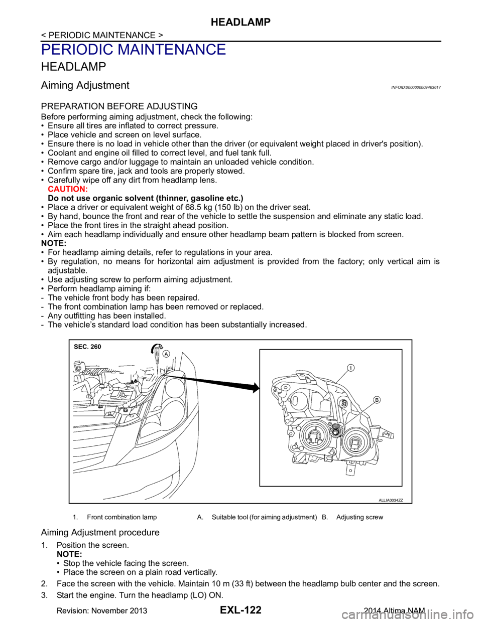
1. Front combination lamp A. Suitable tool (for aiming adjustment) B. Adjusting screw
ALLIA0034ZZ
Revision: November 20132014 Altima NAMRevision: November 20132014 Altima NAM
Page 2390 of 4801

EXL-124
< PERIODIC MAINTENANCE >
FRONT FOG LAMP
FRONT FOG LAMP
Aiming AdjustmentINFOID:0000000009463618
PREPARATION BEFORE ADJUSTING
The fog lamp is a semi-sealed beam type which uses a replaceable halogen bulb. Before performing aiming
adjustment procedure, check the following:
• Ensure all tires are inflated to correct pressure.
• Place vehicle and screen on level surface.
• Ensure there is no load in vehicle other than the driver (or equivalent weight placed in driver's position).
• Coolant and engine oil filled to correct level, and fuel tank full.
• Remove cargo and/or luggage to maintain an unloaded vehicle condition.
• Confirm spare tire, jack and tools are properly stowed.
• Carefully wipe off any dirt from headlamp lens. CAUTION:
Do not use organic solvent (thinner, gasoline etc.)
• Place a driver or equivalent weight of 68.5 kg (150 lb) on the driver seat.
• By hand, bounce the front and rear of the vehicle to settle the suspension and eliminate any static load.
• Place the front tires in the straight ahead position.
• Aim each headlamp individually and ensure other headlamp beam pattern is blocked from screen.
NOTE:
• For headlamp aiming details, refer to regulations in your area.
• By regulation, no means for horizontal aim adjustment is provided from the factory; only vertical aim is
adjustable.
• Use adjusting screw to perform aiming adjustment.
• Perform headlamp aiming if:
- The vehicle front body has been repaired.
- The front combination lamp has been removed or replaced.
- Any outfitting has been installed.
- The vehicle’s standard load condition has been substantially increased.
Aiming Adjustment Procedure
1. Place the screen. NOTE:
• Stop the vehicle facing the wall.
• Place the board on a plain road vertically.
2. Face the vehicle with the screen. Maintain 7.62 m (25.0 ft) between the front fog lamp center and the
screen.
3. Start the engine. Turn the front fog lamp ON. NOTE:
Shut off the headlamp light with the board to prevent from illuminating the adjustment screen.
CAUTION:
Do not cover the lens surface with a tape etc. The lens is made of resin.
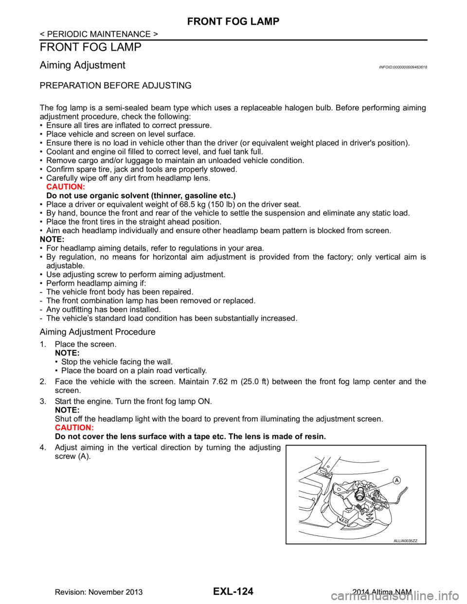
4. Adjust aiming in the vertical direction by turning the adjusting screw (A).
ALLIA0035ZZ
Revision: November 20132014 Altima NAMRevision: November 20132014 Altima NAM
Page 2448 of 4801

EXT-34
< REMOVAL AND INSTALLATION >
SIDE GUARD MOLDING
SIDE GUARD MOLDING
Exploded ViewINFOID:0000000009461013
Removal and InstallationINFOID:0000000009461014
Removal
CAUTION:
Do not apply tack-paper adhesive re mover to body panel surface finished with lacquer-based paints.
• Original side guard molding is affixed to body panel with double-faced adhesive tape.
1. Heat molding to between 30 ° and 40 °C (86 ° to 104 °F) with a heat gun.
2. Gently lift an end of the molding using a suitable tool and cut away tape to remove molding.
3. Remove all remaining traces of tape and adhesive.
Installation
• On vehicles coated with Hard Clear Coat, use double-faced 3M® adhesive tape Product No. 4210 or equiv-
alent, after priming with 3M primer Product No. N200 or C-100 or equivalent.
• The repair parts are also attached with double-faced adhesive tape.
• To re-use existing molding, clean all traces of double sided tape from the molding and apply new double-
faced tape to the molding.
1. Clean the panel surface with isopropyl alc ohol or equivalent to degrease the surface.
2. Using a heat gun, heat the panel and molding tape surface to 30 ° to 40 °C (86 ° to 104 °F).
3. Remove the backing sheet from the tape surface.
4. Press ends by hand and use a roller to apply 5 kg-f (11 ft-lbs) to press molding to door surface. • Apply even pressure along molding to insure proper wet out.
CAUTION:
For maximum adhesion, allow vehic le to set without washing for 24 hours after installation.
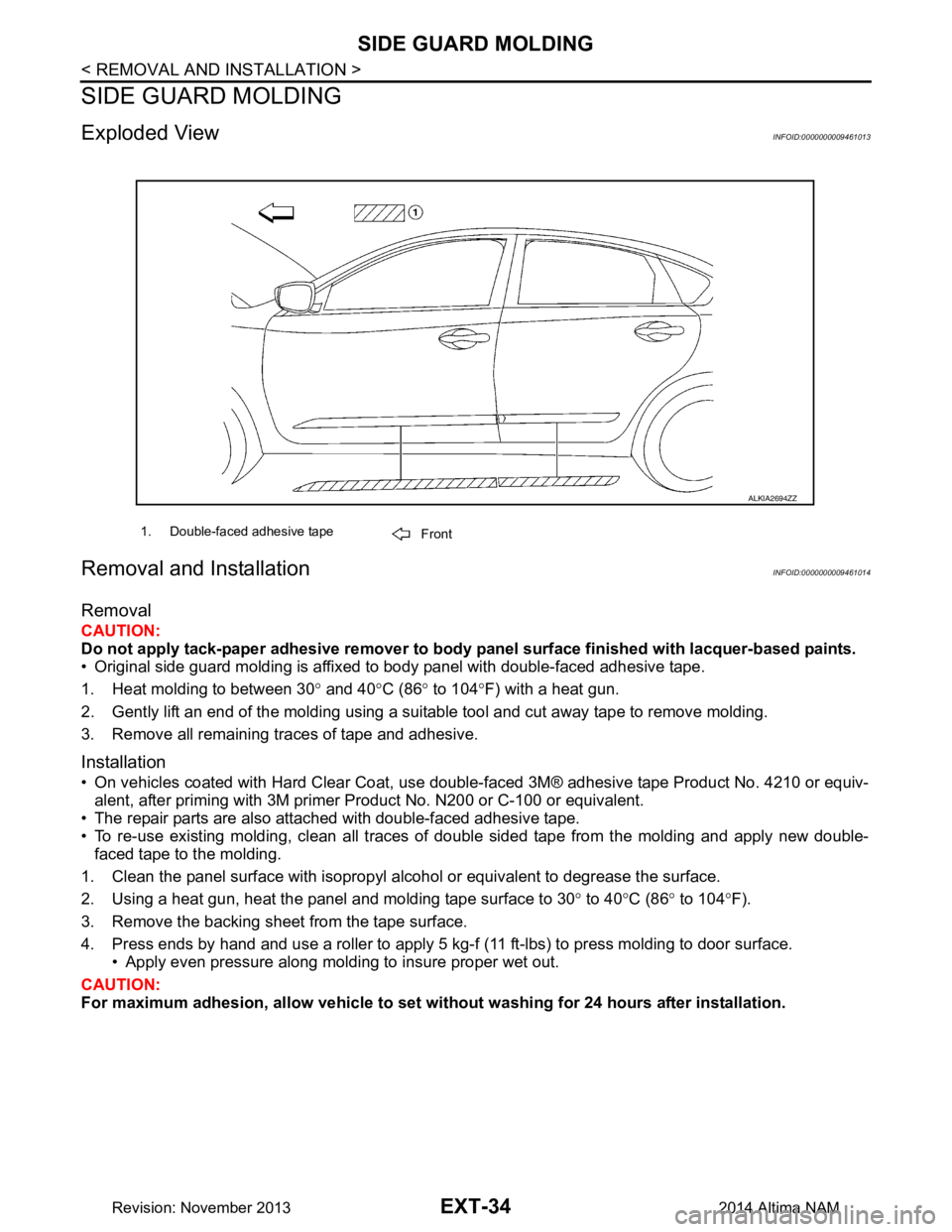
1. Double-faced adhesive tape
Front
ALKIA2694ZZ
Revision: November 20132014 Altima NAM
Page 2482 of 4801

FL-2
< PRECAUTION >
PRECAUTIONS
PRECAUTION
PRECAUTIONS
Precaution for Supplemental Restraint System (SRS) "AIR BAG" and "SEAT BELT
PRE-TENSIONER"
INFOID:0000000009951691
The Supplemental Restraint System such as “A IR BAG” and “SEAT BELT PRE-TENSIONER”, used along
with a front seat belt, helps to reduce the risk or severi ty of injury to the driver and front passenger for certain
types of collision. Information necessary to service the system safely is included in the SR and SB section of
this Service Manual.
WARNING:
• To avoid rendering the SRS inopera tive, which could increase the risk of personal injury or death in
the event of a collision which would result in air bag inflation, all maintenance must be performed by
an authorized NISS AN/INFINITI dealer.
• Improper maintenance, including in correct removal and installation of the SRS, can lead to personal
injury caused by unintent ional activation of the system. For re moval of Spiral Cable and Air Bag
Module, see the SR section.
• Do not use electrical test equipmen t on any circuit related to the SRS unless instructed to in this
Service Manual. SRS wiring harn esses can be identified by yellow and/or orange harnesses or har-
ness connectors.
PRECAUTIONS WHEN USING POWER TOOLS (AIR OR ELECTRIC) AND HAMMERS
WARNING:
• When working near the Airbag Diagnosis Sensor Unit or other Airbag System sensors with the Igni-
tion ON or engine running, DO NOT use air or electri c power tools or strike near the sensor(s) with a
hammer. Heavy vibration could activate the sensor( s) and deploy the air bag(s), possibly causing
serious injury.
• When using air or electric power tools or hammers , always switch the Ignition OFF, disconnect the
battery and wait at least three minutes before performing any service.
General PrecautionINFOID:0000000009460597
WARNING:
When replacing fuel line parts, be sure to observe the following.
• Put a “CAUTION: FLAMMABLE” sign in the work area.
• Be sure to work in a well ventilated area and have a CO
2 fire extinguisher.
• Do not smoke while working on the fuel system. Keep open flames and sparks away from the work
area.
CAUTION:
• Before removing fuel line parts, carry out the following procedures:
- Put drained fuel in an explosi on-proof container and put the lid on securely. Keep the container in
safe area.
- Release fuel pressure from the fuel lines. Refer to EC-182, "Work Procedure"
(QR25DE), EC-687,
"Work Procedure" (VQ35DE).
- Disconnect the battery ground cable.
• Always replace O-rings and clamps with new ones.
• Do not kink or twist tubes when they are being installed.
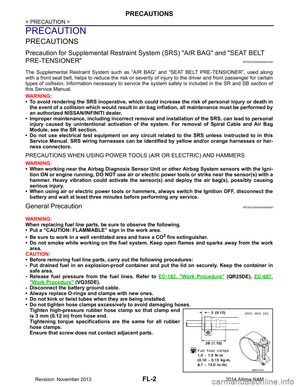
• Do not tighten hose clamps excessi vely to avoid damaging hoses.
Tighten high-pressure rubber hose clamp so that clamp end
is 3 mm (0.12 in) from hose end.
Tightening torque specificati ons are the same for all rubber
hose clamps.
Ensure that screw does not contact adjacent parts.
MMA104A
Revision: November 20132014 Altima NAM